ESP DATSUN 210 1979 Owner's Manual
[x] Cancel search | Manufacturer: DATSUN, Model Year: 1979, Model line: 210, Model: DATSUN 210 1979Pages: 548, PDF Size: 28.66 MB
Page 214 of 548

Condition
Clutch
slips
Clutch
drags
Clutch
TROUBLE
DIAGNOSES
AND
CORRECTIONS
Probable
cause
and
testing
Corrective
action
Slipping
of
clutch
may
be
noticeable
when
any
of
the
following
symptoms
is
encountered
during
operation
I
Car
will
not
respond
to
erigine
speed
during
acceleration
2
Insufficient
car
speed
3
Lack
of
power
during
uphill
driving
Some
of
the
above
conditions
may
also
be
attributable
to
engine
problem
First
determine
whether
engine
or
clutch
is
causing
the
problem
If
slipping
clutch
is
left
unheeded
wear
and
or
overheating
will
occur
on
clutch
facing
to
such
an
extent
that
it
is
no
longer
serviceable
TO
TEST
FOR
SLIPPING
CLurCH
proceed
as
follows
During
upgrade
havelling
run
engine
at
about
40
to
50
km
h
25
to
31
MPH
with
gear
shift
lever
in
3rd
speed
position
shift
into
highest
gear
and
t
the
same
time
rev
up
engine
If
clutch
is
slipping
car
willnot
readily
respond
to
depression
of
accelerator
pedal
Clutch
facing
warn
excessively
Oil
or
grease
on
clutch
facing
Warped
clutch
cover
or
pressure
plate
Replace
Replace
Repair
or
replace
Dragging
clu
tch
is
particularly
noticeable
when
shifting
gears
especially
into
low
gear
TO
TEST
FOR
DRAGGING
CLurCH
proceed
as
follows
I
Start
engine
Disengage
clutch
Shift
into
reverse
gear
and
then
into
Neutral
Gradually
increase
engine
speed
and
again
shift
into
reverse
gear
If
clutch
is
dragging
gear
grating
is
heard
when
shifting
gears
from
Neutral
into
Reverse
2
Stop
engine
and
shift
gears
Conduct
this
test
at
each
gear
position
3
In
step
2
gears
are
shifted
smoothly
except
1st
speed
position
at
idling
a
If
dragging
is
encountered
at
the
end
of
shifting
check
condition
of
synchro
mechanism
in
transmission
b
If
dragging
is
encountered
at
the
beginning
of
shifting
proceed
to
step
4
below
4
Push
change
lever
toward
Reverse
ide
depress
pedal
to
check
for
free
travel
of
pedal
a
If
pedal
can
be
depressed
further
check
clutch
for
condition
b
If
pedal
cannot
be
depressed
further
proceed
to
step
5
below
5
Check
clutch
control
pedal
height
pedal
free
play
free
travel
withdrawal
lever
play
etc
If
any
abnormal
condition
does
not
exist
and
if
pedal
cannot
be
depressed
further
check
clutch
for
condition
Clutch
disc
runout
or
warped
Wear
or
rust
on
hub
splines
in
clutch
disc
Diaphragm
spring
toe
height
out
of
adjustment
or
toe
tip
worn
Worn
or
improperly
installed
parts
Replace
Clean
and
lubricate
with
grease
or
replace
Adjust
or
replace
Repair
or
replace
CL12
Page 290 of 548
0
1
1W
I
u
1
AT172
Fig
AT
8
1
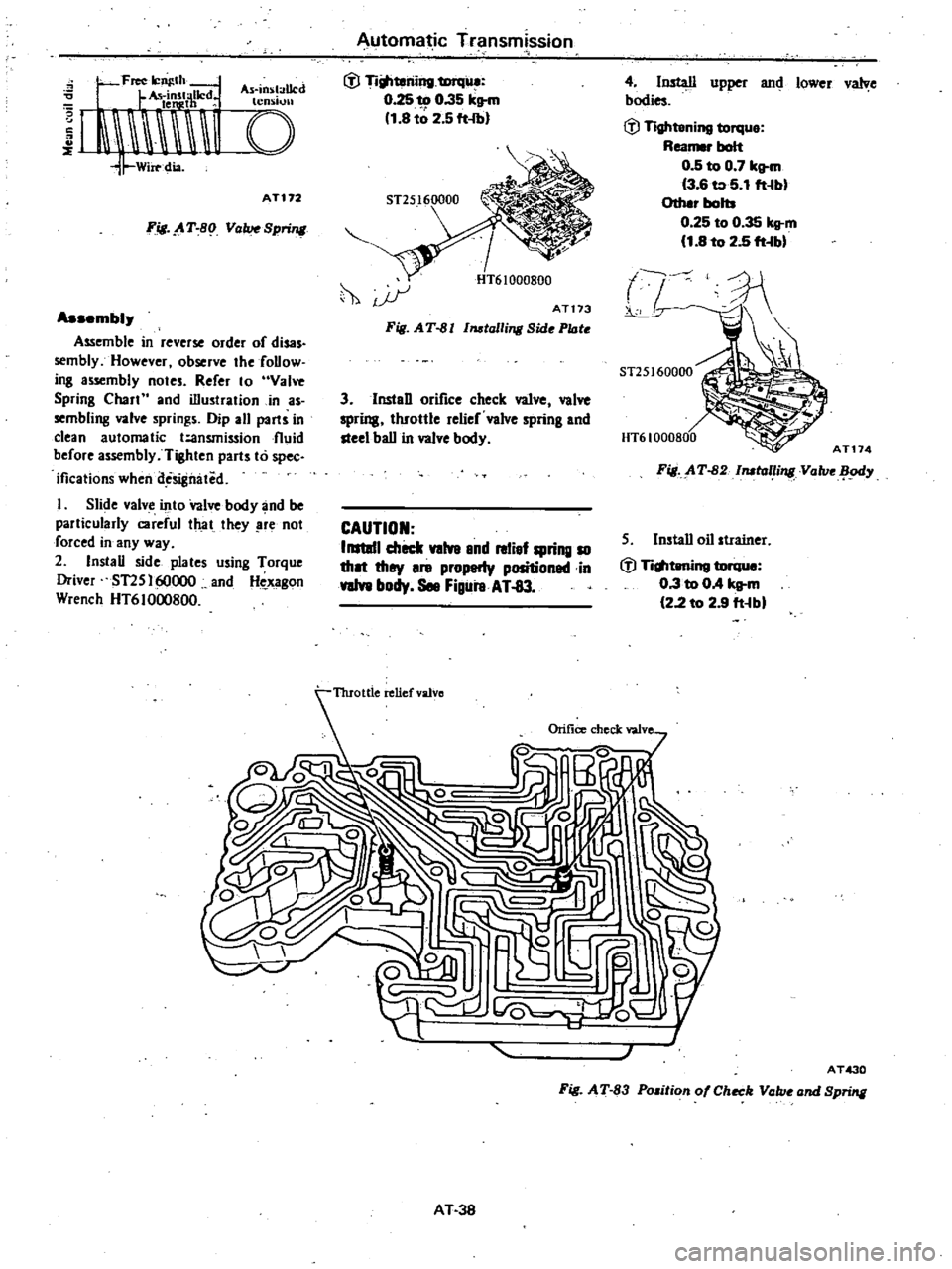
ValveSpring
Assembly
Assemble
in
reverse
order
of
disas
semblyHowever
observe
the
follow
ing
assembly
notes
Refer
10
Valve
Spring
Chall
and
illustration
in
as
sembling
valve
springs
Dip
all
pailS
in
clean
automatic
t
ansmission
fluid
before
assembly
Tighten
parts
to
spec
ificalions
when
des
gmited
I
Slide
valve
into
Valve
body
and
be
palticularIy
careful
that
they
re
not
forced
in
any
way
2
Install
side
plates
using
Torque
Driver
ST2S
160000
and
Hc
xagon
Wrench
HT61000800
Automa
ic
Transm
ssion
tV
Ti
teriing
tmqile
0
25
to
0
35
kll
m
1
8
t
2
5
ft
lbl
4
InsWl
upper
and
lower
valve
bodies
tV
Tightening
torque
Reamer
bait
0
5
to
0
7
kll
m
13
6
to
5
1
ft
bl
Other
bolb
0
25
to
0
35
kg
m
11
8
to
2
5
ft
bl
hi
ST25160000
AT174
0
u
r
ATt73
HT61000800
Fig
AT
82
llIOlalli
Value
ody
S
Install
oil
strainer
tV
Titlltening
torque
0
3
to
OA
kg
m
122
to
2
9
ft
bl
Fig
AT
81
Il1Otalli
Side
Plate
3
lnstaD
orifice
check
valve
valve
spring
throttle
relief
valve
spring
and
steel
ball
in
valve
body
CAUTION
IIIItIII
check
valve
8nd
relief
spring
10
tho
they
8re
properly
positionadin
valve
body
See
Figure
AT
83
J
AT430
Fig
AT
83
Position
of
Check
Value
and
Spring
AT
38
Page 292 of 548
Place
the
vehicle
in
a
pit
and
by
sampling
the
lealeed
oil
deiermine
if
it
is
the
torque
converter
oil
The
torque
converter
oil
has
a
color
like
red
wine
so
it
is
easily
distinguished
from
engine
oil
or
gear
oil
Wipe
off
the
lealeing
oil
and
dust
and
detect
the
spot
of
ill
lell8e
nonflammable
organic
solvent
such
as
carbon
tetrachloride
for
wiping
Raise
the
oil
tcmperature
by
op
erating
the
engine
and
shift
the
lever
to
D
to
increase
the
oil
pressure
The
sp
Q
of
o
1
1I8
u
J1en
be
found
more
easily
Note
As
oil
leakage
from
the
breath
er
does
not
talee
place
except
when
running
at
high
peed
it
iSimpos
sible
to
ate
this
lealcage
with
vehicle
stationary
CHECKING
ENGINE
IDLING
REVOLunON
The
engine
idling
revolution
should
be
properly
adjusted
If
the
engine
revolution
is
too
low
the
e
gine
does
not
operate
smoothly
and
if
too
high
a
strong
shocle
or
creep
develops
when
changing
over
from
ON
to
Dn
or
R
CHECKING
AND
ADJUSTING
KICK
WN
SWITCH
AND
DOWNSH
FT
SOLENOID
When
the
Ieickdown
operation
is
not
made
properly
or
the
speed
chang
ingpoint
is
too
high
check
the
kick
down
switch
downshift
solenoid
and
wiring
between
them
When
the
igni
tion
Ieey
is
po
iti
ned
at
the
1st
stage
and
the
accelerator
pedal
is
depressed
deeply
the
switch
contact
hould
be
closed
and
the
solenoid
should
clicle
If
it
does
not
click
it
indicates
a
defect
Then
check
each
part
with
the
testing
inatrumen15
Auto
lT1atic
Transmissiqn
Fi
J
A
T
84
Down
ltift
Sole
id
Note
Watch
for
oil
leekage
from
tnnsmission
case
INSPECTION
AND
ADJUSTMENT
OF
MANUAL
LINKAGE
The
adjustmcnt
of
manual
linkage
i
equany
important
as
Inspection
of
Oil
Level
for
the
automatic
transmis
sion
Therefore
great
care
should
be
cxercised
oecause
incorrect
adjustment
will
result
in
the
breakdown
of
the
transmission
Inspection
pun
the
selector
lever
toward
you
and
turn
it
as
far
as
p
to
range
where
clicks
will
be
ell
by
the
hand
This
is
the
detent
of
manual
valve
in
the
valve
body
and
indicates
the
corrett
position
of
the
lever
Inspect
whether
the
pointer
of
selector
dial
corresponds
to
this
point
and
also
whether
the
lever
comes
in
alignment
with
the
stepping
of
posi
iion
plate
when
itis
released
CHECKING
AND
ADJUSTING
INHIBITOR
SWITCH
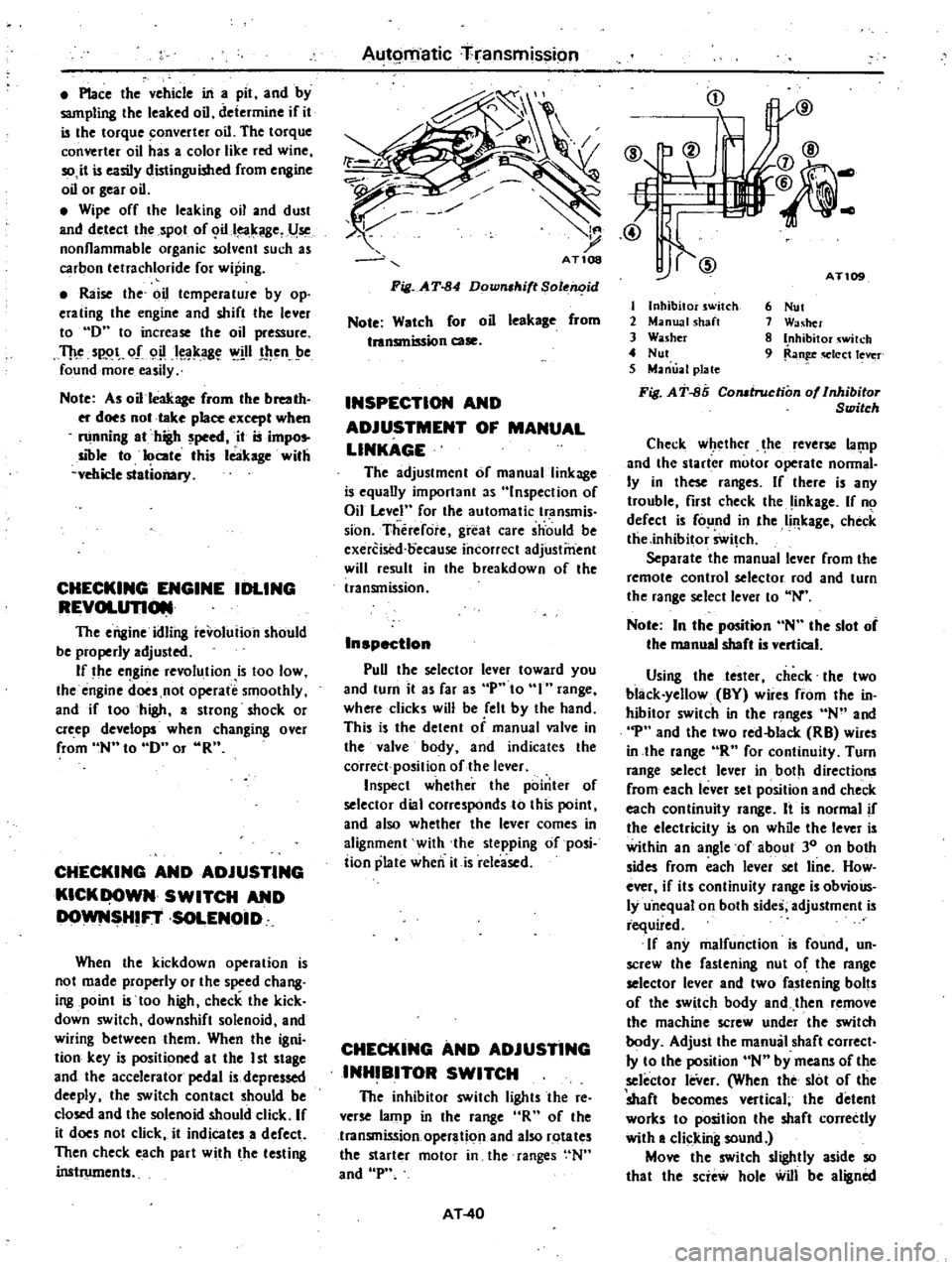
The
inhibitor
switch
lights
the
re
verse
lamp
in
the
range
R
of
the
transmission
operation
and
also
rotates
the
starter
motor
in
the
ranges
N
and
P
AT
40
i
j
tI
IlV
@
@
AT
I
Inhibitor
switch
2
Manual
shaft
3
Washer
4
Nut
5
Manual
plate
Fi
J
AT
85
Comtruction
of
Inhibitor
Switch
6
Nut
1
Washer
8
Inhibitor
wilch
9
Ran
q
Iect
lever
Check
w
ethcr
he
leverse
lal
1p
and
the
starter
motor
operate
nonnal
Iy
in
these
ranges
If
there
is
any
trouble
first
check
the
inkage
If
no
defect
is
fo
nd
in
the
Ii
leage
check
tlie
inhibitor
Swi
ch
Separate
the
manual
lever
from
the
remote
control
selector
rod
and
turn
the
range
select
lever
to
N
Note
In
the
position
N
the
slot
of
the
manual
shaft
is
vertical
Using
the
tester
check
the
two
black
yellow
BY
wire
from
the
in
hibitor
switch
in
the
ranges
N
and
p
and
the
two
red
blacle
RB
wires
in
the
lange
R
for
continuity
Turn
range
select
lever
in
both
directions
from
each
lever
set
position
and
check
each
continuity
range
It
is
normal
if
the
electricity
is
on
while
the
lever
is
within
an
angle
of
about
30
on
both
sides
from
each
lever
set
line
How
ever
if
its
continuity
range
is
obvioUs
ly
u
nequal
on
both
sides
adjustment
is
required
If
any
malfunction
is
found
un
screw
the
fastening
nut
o
the
range
selector
lever
and
two
fastening
bolts
of
the
switch
body
and
then
remove
the
machine
screw
under
the
switch
body
Adjust
the
manual
shaft
correct
Iy
to
the
position
N
by
means
of
the
selector
leVer
When
the
slot
of
the
shaft
becomes
vertical
the
detent
worles
to
position
the
shaft
correctly
with
a
clicking
sound
Move
the
switch
slightly
aside
so
that
the
scie
hole
will
be
aligned
Page 293 of 548
with
the
pin
hole
of
the
internal
rotor
combined
with
the
manual
shaft
and
check
their
alignment
by
inserting
a
1
5
mm
0
059
in
diameter
pin
into
the
holes
If
the
alignment
is
correct
fasten
the
switch
body
with
the
bolts
pull
out
the
pin
tighten
up
the
screw
in
the
hole
and
fasten
the
selector
lever
as
before
Check
the
continuity
pin
with
the
lesler
If
Ihe
malfunc
tion
still
remains
replace
the
inhibitor
switch
STALL
TEST
The
purpose
of
this
test
is
to
check
the
transmission
and
engine
for
trou
ble
by
measuring
the
maximum
num
bers
of
revoiutions
o
the
cngine
while
vehicle
is
held
in
a
stalled
condition
The
carburetor
is
in
fullthrollle
opera
tion
with
the
selector
lever
in
ranges
1
2
and
I
respectively
Com
pale
the
measured
results
with
the
standard
values
Components
to
be
tested
and
test
itelJUl
I
Clutches
brake
and
band
in
trans
mission
for
slipping
2
Torque
converter
for
proper
func
tioning
3
Engine
for
overall
properly
STAU
TEST
PROCEDURES
Before
testing
check
the
engine
oil
and
torque
converter
oil
warm
up
the
engine
cooling
w
ter
to
suitable
tem
perature
by
running
at
1
200
rpm
with
the
selector
lever
in
the
range
P
for
sevcral
minutes
Warm
up
the
torque
converter
oil
to
suitable
temperature
60
to
lOOoC
140
to
2120F
I
Mount
the
engine
tachometer
at
a
location
that
allows
good
visibility
from
the
driver
s
seat
and
put
a
mark
on
specified
revolutions
on
the
meter
2
Secure
the
front
and
rear
wheels
with
chocks
and
apply
the
hand
brake
Be
SIIre
to
depress
the
brake
pedal
firmly
with
the
left
foot
before
de
pressing
the
accelerator
pedal
3
Throw
the
selector
lever
into
the
range
11
4
Slowly
depress
the
accelerator
pedal
until
the
throttle
valvc
is
fully
Automatic
Transmission
opened
Quickly
read
and
record
the
engine
revolution
when
the
engine
begins
to
rotate
steadily
and
then
release
the
accelerator
pedal
5
Shift
the
selector
lever
to
N
and
operate
the
engine
at
approxi
mately
1
200
rpm
for
more
than
one
minute
to
cool
down
the
torque
con
verter
oil
and
coolant
6
Make
similar
staU
tests
in
ranges
2
I
and
R
CAUTION
The
dill
test
operstion
81
specified
in
i18m
4
should
be
I118de
within
fiv
lIeonds
If
it
tBkes
too
long
the
oil
If
and
the
cluti
hn
blllke
and
b
nd
elll
ly
I
Suf
ficient
cooling
time
should
be
given
r
eech
test
for
the
four
IlInges
0
Z
1
end
R
JUDGEMENT
High
stall
revolution
more
than
staitdard
revolution
If
the
engine
levolulion
in
stall
condi
ion
is
higher
than
the
standard
values
it
indicates
that
onc
or
more
clutches
in
the
transmission
are
slipping
and
therefore
no
further
test
is
required
For
the
following
abnormalities
the
respective
causes
are
presumed
High
rpm
in
all
ranges
low
line
pr
ssure
High
rpm
in
0
2
and
I
and
normal
rpm
in
6R
Rear
clutch
slipping
High
rpm
in
D
and
2
and
normal
rpm
in
One
way
clutch
slipping
High
Ipm
in
R
only
Front
clutch
or
low
and
reverse
brake
slipping
To
determine
which
is
slipping
front
clutch
or
low
and
reverse
brake
a
road
test
is
needed
If
while
coasting
after
starting
with
the
levcr
in
I
range
engine
braking
does
not
work
properly
the
low
and
reverse
brake
is
slipping
Otherwise
the
front
clutch
is
slipping
Slipping
of
the
band
brake
is
diffi
cuJt
to
ascertain
However
jf
it
occurs
with
the
lever
in
1
range
engine
AT
41
revolution
increases
up
to
the
same
level
as
in
1st
range
It
is
impossible
to
check
it
in
the
stall
test
2
Standard
stall
rnoluiion
If
the
engine
revoluiion
in
stall
ondition
is
within
he
standard
values
the
control
elements
are
nOf
mally
operating
in
the
ranges
D
2n
I
and
R
Also
the
engine
and
one
way
clutch
of
the
torque
converter
are
norinal
in
performance
and
operation
The
one
way
clutch
of
the
torque
converter
however
sometimes
sticks
This
is
determined
in
the
road
test
3
Lower
stall
revolution
than
lIand
ard
revolution
If
the
engine
revolution
in
stall
condition
is
lower
than
the
standard
values
it
indicates
that
the
engine
is
in
abnormal
condition
or
the
torque
con
verter
s
one
way
clutch
is
slipping
4
O
hers
I
If
the
accelerating
performance
is
poor
until
vehicle
speed
of
approxi
mately
SO
kmfh
30
MPH
is
attained
and
then
normal
beyond
that
speed
it
can
be
judged
that
the
torque
con
verte
c
s
one
way
clutch
is
slipping
2
If
the
torque
converter
sane
way
dutch
sticks
vehicle
speed
can
not
exceed
approximately
80
kmfh
SO
MPH
in
the
road
tesl
In
such
a
case
the
torque
converter
oil
tem
perature
rises
abnormally
and
so
special
care
is
required
3
If
the
transmission
does
not
op
erate
properly
at
all
vehicle
speeds
it
indicates
poor
engine
performance
ROAD
TEST
An
accurate
knowledge
of
the
au
to
matic
transmission
is
required
for
an
exact
diagnosis
II
is
recommended
that
a
diagnosis
guide
chart
with
the
standard
vehicle
speeds
for
each
stage
of
the
up
and
down
shiftings
be
prepared
Measured
vehicle
speeds
are
to
be
filled
in
the
adjoining
column
after
each
testing
Also
it
is
advisable
to
mount
a
stopper
for
positioning
the
throttle
opening
Page 297 of 548

JUDGEMENT
IN
MEASURING
LINE
PRESSURE
Low
idling
line
pressure
in
the
ranges
D
2
R
and
P
This
can
be
attributed
to
trouble
in
the
pressure
supply
system
or
too
low
output
of
power
caused
by
I
A
worn
oil
pump
2
An
oil
pressure
leak
in
the
oil
pump
valve
body
or
case
3
A
sticking
regulator
valve
2
Low
idling
line
pressure
i
n
cer
tain
ranges
only
This
is
presumably
caused
by
an
oil
leak
in
the
devices
or
circuits
con
nected
to
the
relevant
ranges
I
When
there
is
an
oil
leaJi
in
the
rear
clutch
and
governor
the
line
pressure
in
on
2
and
I
are
low
but
the
pressure
i
nonnal
in
R
2
When
an
oil
leak
occurs
in
the
low
and
reverse
brake
circuit
the
line
pressure
in
oR
and
P
are
low
b
t
the
pressure
is
normal
in
0
2
and
I
3
High
idling
line
pressure
Thi
is
presumably
caused
by
an
increased
aC
1ulT
t
rott
e
pr
ssure
owing
to
a
leak
in
the
vacuum
tube
or
diaphragin
or
by
an
increased
line
Automatic
Transmission
pressure
due
to
a
sticking
regulator
valve
Vacuum
leakage
is
checked
by
directly
measuring
the
negative
pres
sure
after
removing
the
vacuum
pipe
A
puncture
of
the
vacuum
dia
phragm
can
be
easily
ascertained
because
the
torque
converter
oil
is
absorbed
into
the
engine
and
the
exhaust
pipe
emits
white
smoke
4
Item
to
be
checked
when
the
Ii
e
pressure
is
increasing
In
this
c
1eck
the
line
pressure
should
be
measured
with
vacuums
of
300
mmHg
Il
SI
inHg
and
0
mmHg
0
inHg
in
accordance
with
the
staIl
test
procedure
i
If
the
line
pressure
does
not
in
crease
despite
the
vacuum
decrease
check
whether
the
vacuum
rod
is
i
corporated
2
If
the
line
pressure
does
not
meet
tile
standard
iUs
caused
mostly
by
a
sticking
pressure
regulating
valve
pres
sure
regulating
valve
plug
or
amplifier
TROUBLE
SHOOTING
CHART
INSPECTING
ITEMS
I
Inspection
with
automatic
trans
mission
on
vehicle
AT
45
A
Oil
level
B
Range
select
linkage
C
Inhibitor
switch
and
wiring
D
Vacuum
diaphragm
and
piping
E
Downshift
solenoid
kickdown
switch
and
wiring
F
Engine
idling
rpm
G
Oil
pressure
throttle
H
Engine
stall
rpm
I
Rear
lubrication
J
Control
valve
manual
K
Governor
valve
L
Band
servo
M
Transmission
air
check
N
Oil
quality
o
Ignition
switch
and
starter
motor
P
Engine
adjustment
and
brake
in
spection
2
Inspection
after
inspecting
auto
matic
transmission
on
vehicle
m
Rear
clutch
n
Front
clutch
q
Band
brake
r
Low
and
reverse
brake
s
Oil
pump
t
Leakage
of
oil
passage
u
One
way
clutch
of
troque
converter
v
One
way
clutch
of
transmission
w
Front
clutch
check
ball
x
Parking
linkage
y
Planetary
gear
Page 338 of 548
Front
Axle
Front
Suspension
TROUBLE
DIAGNOSES
AND
CORRECTIONS
Condition
Vibration
shock
and
shimmy
of
steering
wheel
Vibration
Loose
connection
of
the
serration
parts
and
wear
of
each
part
of
linkage
cause
vibration
of
front
wheels
and
steering
wheel
vibration
This
is
very
noticeable
when
trav
elling
on
rough
road
Shock
When
the
front
wheels
are
travelling
on
bumpy
roads
the
play
of
the
steering
linkage
is
transmitted
to
the
steering
wheel
This
is
especially
noticeable
when
travelling
on
rough
road
Shimmy
Abnormal
vibration
of
the
front
suspension
system
nd
the
whole
steering
linkage
which
occu
at
specific
speeds
Car
pulls
to
right
or
left
When
driving
with
hands
off
the
steering
wheel
on
a
flat
road
the
car
gently
swerves
to
right
or
left
Note
A
faulty
rear
suspension
may
also
be
the
cause
of
this
problem
and
therefore
see
ebo
Section
RA
Proba
b
Ie
ca
use
Improper
tire
pressure
Imbalance
and
deformation
of
road
wheel
Unevenly
worn
tire
or
insufficient
tight
ening
of
wheel
nuts
Improperly
adjusted
or
worn
front
wheel
bearing
Faulty
wheel
alignment
Worn
transverse
link
bushings
Insufficiently
tightened
steering
gear
hous
ing
Wear
of
steering
linkage
Worn
suspension
ball
joint
Excessive
backlash
due
to
improper
adjust
ment
of
the
steering
gear
box
Damaged
idler
arm
Worn
column
bearing
weakened
column
bearing
spring
or
loose
drmp
Malfucntion
of
shock
absorber
inside
the
strut
or
loose
install3t
on
b9
t5
Imbalance
of
car
l
e
Improper
tire
pressure
or
insufficient
tight
ening
of
wheel
nuts
Difference
in
wear
and
tear
of
right
and
left
tire
treads
Incorrect
adjustment
or
abrasion
of
front
wheel
bearing
Collapsed
or
twisted
front
spring
Incorrect
wheel
alignment
Incorrect
brake
adjustment
binding
Worn
rubber
bushings
for
transverse
link
and
tension
rod
Deformed
steering
linkage
and
transverse
link
and
tension
rod
Imbalance
of
car
level
FA
16
Corrective
action
Adjust
Correct
the
imbal
ap
9f
r
B4I
e
Replace
or
tighten
Adjust
or
tighten
Adjust
Replace
Retighten
Replace
faulty
parts
Replace
Adjust
correctly
Replace
Replace
or
retighten
Replace
or
retighten
Correct
the
imbal
ance
Adjust
or
tighten
Replace
tires
Adjust
or
replace
Replace
Adjust
Adjust
Replace
Replace
Correct
the
imbal
ance
Page 352 of 548
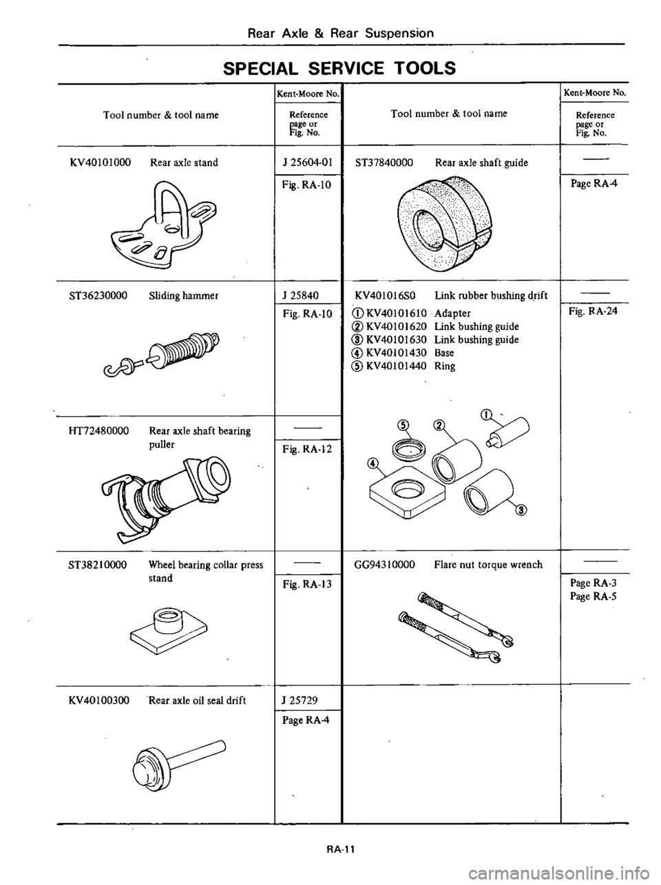
Rear
Axle
Rear
Suspension
SPECIAL
SERVICE
TOOLS
Tool
number
tool
name
KV40101000
Rear
axle
stand
ST36230000
Sliding
hammer
esPY
HT72480000
Rear
axle
shaft
bearing
puller
ST38210000
Wheel
bearing
collar
press
stand
KV
401
00300
Rear
axle
oil
seal
drift
Kent
Moore
No
Reference
page
or
Fig
No
J
25604
01
Fig
RA
1O
J
25840
Fig
RA
1O
Fig
RA
12
Fig
RA
13
J
25729
Page
RA
4
Tool
number
tool
name
ST37840000
Rear
axle
shaft
guide
KV40l016S0
CD
KV40
10
I
610
V
KV40101620
ID
KV4010l630
@
KV40101430
CID
KV4010144
Link
rubber
bushing
drift
Adapter
Link
bushing
guide
Link
bushing
guide
Base
Ring
GG943
1
0000
Flare
nut
torque
wrench
RA
ll
Kent
Moore
No
Reference
page
or
Fig
No
Page
RA
4
Fig
RA
24
Page
RA
3
Page
RA
5
Page 360 of 548
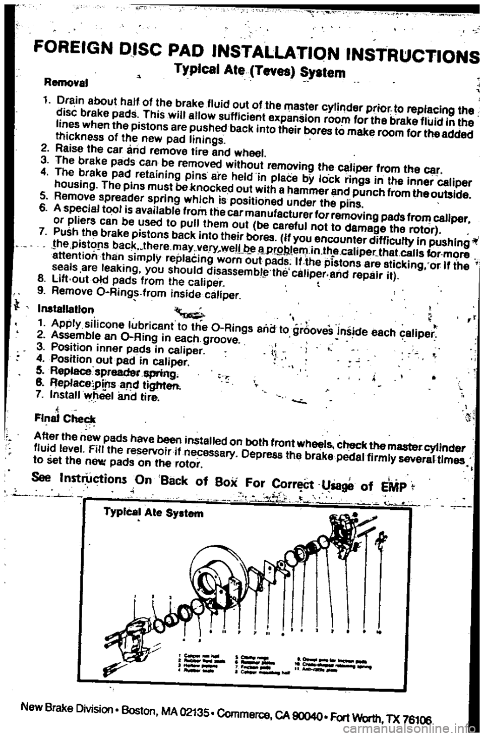
FOREIGN
DISC
PAD
INSTALLATION
INSTRUCTIONS
Typical
Ate
Teves
System
Removel
1
Drain
about
half
of
the
brake
fluid
out
of
the
master
cylinder
prior
to
replacing
the
disc
brake
pads
This
will
allow
sufficient
expansion
room
for
the
brake
fluid
in
the
lines
when
the
pistons
are
pushed
back
into
their
bores
to
make
room
for
the
added
Ihickness
of
the
new
pad
linings
2
Reise
the
car
and
lemove
tire
and
wheel
3
The
breke
pads
can
be
removed
without
lemovinll
the
caliper
from
the
car
4
The
brake
pad
reteining
pins
are
held
in
plaCe
bY
lock
rinlls
in
Ihe
inner
caliper
housing
The
pins
must
be
knocked
out
with
e
hammel
end
punch
from
theoulllide
5
Remove
spreader
spring
which
is
positioned
under
the
pins
6
A
special
tool
is
available
flom
the
car
manufacturer
forremoving
pads
from
caliper
or
pliers
can
be
used
to
pull
them
oul
be
careful
not
to
damage
the
rotor
7
Push
Ihe
brake
pistons
back
into
their
boros
If
you
encounter
difficulty
in
pushingil
he
pistofls
back
lhere
may
very
weIL
Wr9Jl
l
ern
in
lh
e
caliper
that
calls
for
more
attention
than
simplY
replecing
worn
out
pads
IUhe
pistons
are
eticking
or
If
the
seals
are
leaking
you
should
disassembl
the
caliper
and
repair
il
8
Lift
out
old
pads
from
Ihe
caliper
9
Remove
O
Ring
from
inside
caliper
Inslallatlon
II
1
Apply
silicone
lubricanl
to
Ihe
O
Rings
ana
to
grooveS
inside
each
caliper
2
Assemble
an
O
Ring
in
each
groove
3
Position
innor
pads
in
caliper
4
Position
oulpad
in
caliper
5
Replacespreadet
spring
8
ReplaceiPtnsaM
lighter
7
Install
wheel
and
lire
l
Final
Checl
A
Iter
Ihe
new
padS
have
been
installed
on
bolh
front
wheel
check
the
master
cylinder
fluid
level
Rlllhe
reservoiril
necessary
Depress
Ihe
brake
pedal
firmly
severaUlmes
to
sellhe
new
pads
on
he
rotor
i
See
Inst
ctionsOnBat
k
of
Box
For
rr
l8ge
of
EMP
l
iL
1
f
J
TypIcal
Ale
System
New
Brake
Division
Boston
MA
02135
Commerce
CA
90040
Fort
Worth
TX
76106
Page 363 of 548

6
Apply
P
B
C
grease
to
yoke
slid
ing
part
of
cylinder
Then
reposition
bias
ring
so
that
groove
of
bias
ring
coincides
with
yoke
7
Leaving
yoke
springs
inserted
lightly
into
cylinder
groove
assemble
cylinder
body
and
yoke
by
pushing
or
tapping
yoke
lightly
BA570
Fig
BR
19
A
embling
Yoke
and
Cylinder
8
Install
air
bleeder
valve
on
caliper
INSTAlLATION
1
Install
in
reverse
procedure
of
removal
CAUTION
When
installing
brake
tube
use
Flare
Nut
Torque
Wrench
6694310000
fJ
Tightening
tOlque
Calipel
securing
bolts
4
6
to
6
1
kll
m
33
to
44
ft
lb
Brake
tube
flere
nuts
1
5to
1
8
kg
m
11
to
13
ft
Ib
2
After
installing
pad
bleed
air
from
system
Brake
System
ROTOR
REMOVAL
Refer
to
Front
Axle
Section
FA
for
removal
Note
As
this
value
increases
wear
occurs
progressively
vibration
cor
responding
to
revolution
of
tire
may
often
be
tmnsmitted
to
in
terior
of
car
INSPECTION
Check
the
following
items
and
if
necessary
replace
Checks
can
be
made
by
removing
only
wheel
Sliding
surface
If
there
are
cracks
or
considerable
chips
replace
2
Runout
Adjust
wheel
bearing
correctly
Using
a
dial
gauge
measure
runout
at
the
center
of
rotor
pad
contact
sur
face
Runout
limit
less
than
0
12
mm
0
0047
in
Total
indicator
reading
BR025A
Fig
BR
20
Mecuuring
Runout
3
Parallelism
Measure
thickness
of
entire
periph
cry
of
rotor
using
a
micrometer
Parallelism
when
new
less
than
0
03
mm
0
0012
in
BR
9
Fig
BR
21
Measuring
Parallelism
4
Thickness
If
rotor
thickness
is
beyond
wear
limit
replace
rotor
When
correcting
thickness
be
sure
that
the
thickness
after
correction
does
not
exceed
the
limit
Standard
thickness
10
0
mm
0
394
in
Wear
limit
more
than
8
4
mm
0
331
in
INSTALLATION
Install
rotor
in
reverse
order
of
removal
Adjust
wheel
bearing
preload
correctly
Refer
to
Front
Axle
Sec
tion
FA
for
adjustment
ifl
Tightening
torque
Rotor
to
wheel
hub
3
9
to
5
3
kg
m
28
to
38
ft
rb
Page 380 of 548
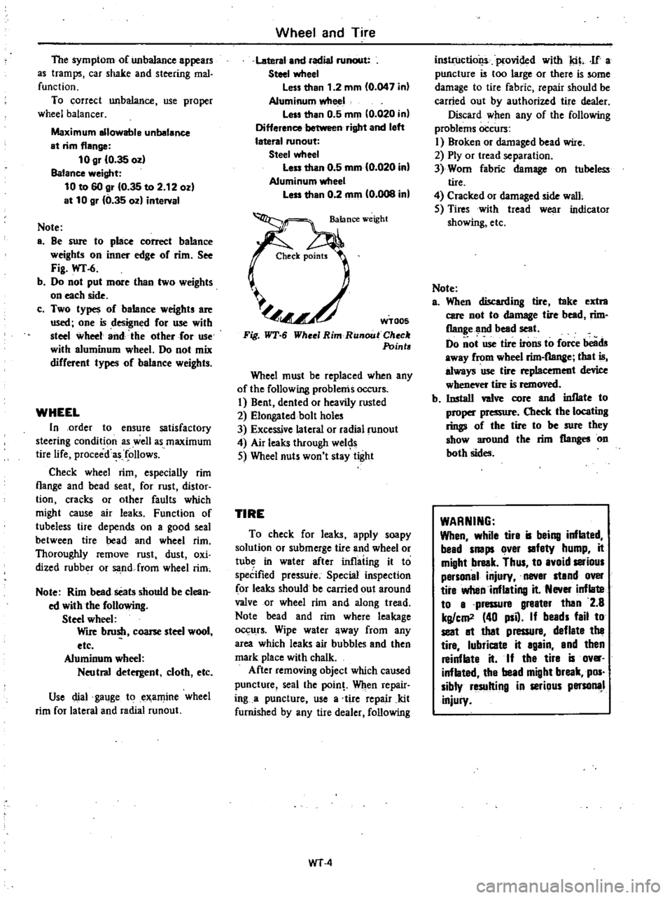
The
symptom
of
unbalance
appears
as
tramps
car
shake
and
steering
mal
function
To
correct
unbalance
use
proper
wheel
balancer
Maximum
allowable
unbalance
at
rim
flange
10
gr
10
35
ozl
Balance
weight
10
to
60
gr
10
35
to
2
12
ozl
at
10
gr
10
35
ozl
interval
Note
a
Be
sure
to
place
correct
balance
weights
on
inner
edge
of
rim
See
Fig
wr
6
b
Do
not
put
mOle
than
two
weights
on
each
side
c
Two
types
of
balance
weights
are
used
one
is
designed
for
use
with
steel
wheel
and
the
other
for
use
with
aluminum
wheel
Do
not
mix
different
types
of
balance
weights
WHEEL
In
order
to
ensure
satisfactory
steering
condition
as
well
as
maximum
tire
life
proceed
follows
Check
wheel
rim
especially
rim
flange
and
bead
seat
for
rust
distor
tion
cracks
or
other
faults
which
might
cause
air
leaks
Function
of
tubeless
tire
depends
on
a
good
seal
between
tire
bead
and
wheel
rim
Thoroughly
remove
rust
dust
oxi
dized
rubber
or
sa
nd
from
wheel
rim
Note
Rim
bead
seats
should
be
clean
ed
with
the
following
Steel
wheel
Wile
brush
coone
steel
wool
etc
Aluminum
wheel
Neutral
detergent
cloth
etc
Use
dial
gauge
to
examine
wheel
rim
for
lateral
and
radial
runout
Wheel
and
Tire
Lateral
and
radial
runout
Steel
wheel
less
than
1
2
mm
0
047
in
Aluminumwlte
1
lass
than
0
5
mm
10
020
in
Difference
right
and
left
lateral
runout
Steel
wheel
leu
than
0
5
mm
10
020
in
Aluminum
wheel
less
than
0
2
mm
0
008
in
C
JeCk
points
l
Fig
WT
6
WT005
Whee
Rim
RUllout
Check
Points
Wheel
must
be
replaced
when
any
of
the
following
problems
occurs
I
Bent
dented
or
heavily
rusted
2
Elongated
bolt
holes
3
Excessive
lateral
or
radial
runout
4
Air
leaks
through
wel
s
5
Wheel
nuts
won
t
stay
tight
TIRE
To
check
for
leaks
apply
soapy
solution
or
submerge
tire
and
wheel
or
tub
in
water
after
inflating
it
to
speCified
pressure
Special
inspection
for
leaks
should
be
carried
out
around
valve
or
wheel
rim
and
along
tread
Note
bead
and
rim
where
leakage
0
11rs
Wipe
water
away
from
any
area
which
leaks
air
bubbles
and
then
mark
place
with
chalk
After
removing
object
which
caused
puncture
seal
the
pain
Wilen
repair
ing
a
puncture
use
a
tire
repair
kit
furnished
by
any
tire
dealer
following
WT
4
inslrt1ctiol
iplovided
with
tit
If
a
puncture
is
too
large
or
there
is
some
damage
to
tire
fabric
repair
should
be
carried
out
by
authorized
tire
dealer
Discard
when
any
of
the
following
problems
occurs
I
Broken
or
damaged
bead
wire
2
Ply
or
tread
separation
3
Worn
fabric
damage
on
tubeless
tire
4
Cracked
or
damaged
side
wall
5
Tires
with
tread
wear
indicator
showing
etc
Note
a
When
discarding
tire
take
extra
care
not
to
damage
tire
bead
rim
flange
and
bead
seat
Do
ot
use
tire
irons
to
foree
beads
away
from
wbeel
rim
flange
that
is
always
use
tire
replacement
device
whenever
tire
is
removed
b
Install
wive
core
and
inflate
to
proper
pressure
Check
the
locating
rings
of
the
tire
to
be
sure
they
show
around
the
rim
flanges
on
both
sides
WARNING
When
while
tire
is
being
inflated
bead
snaps
over
safety
hump
it
might
break
Thus
to
avoid
satious
personal
injury
never
stand
over
tire
when
inflating
it
Never
inflate
to
a
pressure
greater
then
2
8
kg
em
40
psQ
If
beads
fail
to
seat
It
that
pressure
deflate
the
tire
lubricate
it
again
and
then
reinflate
it
If
the
tire
is
ov
inflated
the
bead
might
break
pos
sibly
resulting
in
serious
persona
injury