tire type DATSUN 210 1979 Service Manual
[x] Cancel search | Manufacturer: DATSUN, Model Year: 1979, Model line: 210, Model: DATSUN 210 1979Pages: 548, PDF Size: 28.66 MB
Page 144 of 548
INSPECTION
Entire
system
I
Make
a
thorough
vjsual
check
of
E
G
R
control
system
If
necessary
wipe
away
oil
to
facilitate
inspection
If
any
hoses
are
cracked
or
broken
replace
2
With
engine
stopped
inspect
E
G
R
control
valve
for
any
indication
of
binding
or
sticking
by
moving
dia
phragm
of
control
valve
upwards
with
a
finger
3
With
engine
running
inspect
E
G
R
control
valve
and
thermal
vacu
um
valve
for
normal
operation
1
When
engine
coolant
tempera
tun
is
low
Make
sure
that
E
G
R
control
valve
does
not
operate
when
engine
speed
is
increased
from
idling
to
3
000
to
3
500
rpm
Place
a
finger
on
the
diaphragm
of
E
G
R
control
valve
to
check
for
valve
operation
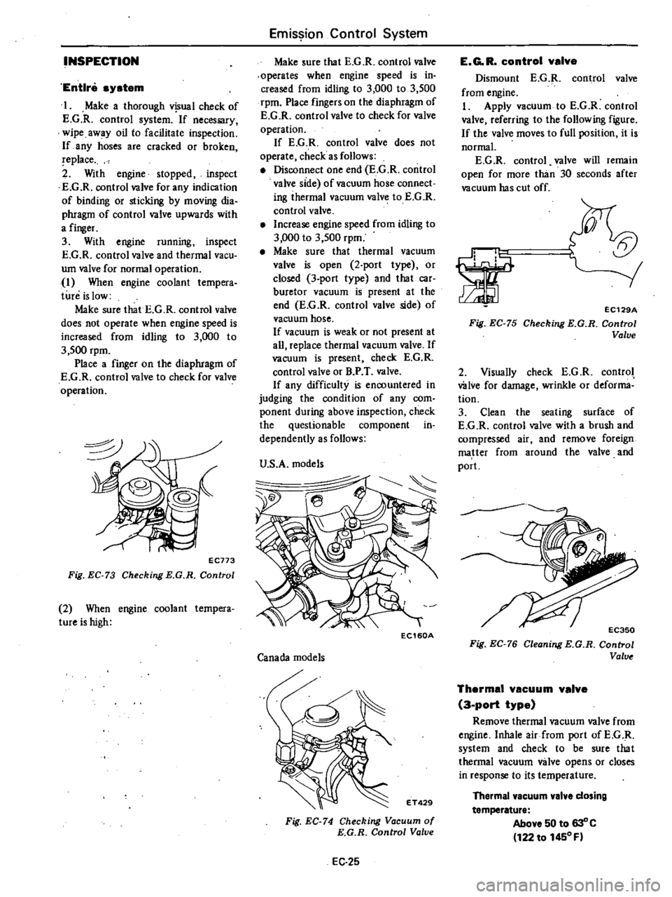
EC773
Fig
EC
73
Checking
E
G
R
Control
2
When
engine
coolant
tempera
tureishigh
Emission
Control
System
Make
sure
that
E
G
R
control
valve
operates
when
engine
speed
is
in
creased
from
idling
to
3
000
to
3
500
rpm
Place
fingers
on
the
diaphragm
of
E
G
R
control
valve
to
check
for
valve
operation
If
E
G
R
control
valve
does
not
operate
check
as
follows
Disconnect
one
end
E
G
R
control
valve
side
of
vacuum
hose
connect
ing
ihermal
vacuum
valve
to
E
G
R
control
valve
Increase
engine
speed
from
idling
to
3
000
to
3
500
rpm
Make
sure
that
thermal
vacuum
valve
is
open
2
port
type
or
closed
3
port
type
and
that
car
buretor
vacuum
is
present
at
the
end
E
G
R
control
valve
side
of
vacuum
hose
If
vacuum
is
weak
or
not
present
at
all
replace
thermal
vacuum
valve
If
vacuum
is
present
check
E
G
R
control
valve
or
B
P
T
valve
If
any
difficulty
is
encountered
in
judging
the
condition
of
any
com
ponent
during
above
inspection
check
the
questionable
component
in
dependently
as
follows
U
S
A
models
Ie
EC160A
Canada
models
ET429
Fig
EC
74
Checking
Vacuum
of
E
G
R
Control
Valve
EC
25
E
G
R
control
valve
Dismount
E
G
R
control
valve
from
engine
I
Apply
vacuum
to
E
G
R
control
valve
referring
to
the
following
figure
If
the
valve
moves
to
full
position
it
is
normal
E
G
R
control
valve
will
remain
open
for
more
than
30
seconds
after
vacuum
has
cut
off
5t
orr
rl
1
1
Fig
EC
75
EC129A
Checking
E
G
R
Control
Valve
2
Visually
check
E
G
R
control
wive
for
damage
wrinkle
or
deforma
tion
3
Clean
the
seating
surface
of
E
G
R
control
valve
with
a
brush
and
compressed
air
and
remove
foreign
matter
from
around
the
valve
and
port
Fig
EC
76
Cleoning
E
G
R
Control
Valve
Thermal
vacuum
valve
3
port
type
Remove
thermal
vacuum
valve
from
engine
Inhale
air
from
port
ofE
G
R
system
and
check
to
be
sure
that
thermal
vacuum
valve
opens
or
closes
in
response
to
its
temperature
Thermal
vacuum
valve
dosing
temperature
Above
50
to
630
C
122
to
1450
F
Page 150 of 548
INSPECTION
Entire
system
U
S
A
MIT
models
except
FU
mo
el
1
Ensure
that
wiring
connectors
are
tight
in
pla
ce
2
Ensure
that
vacuum
hoses
are
properly
cof
1o
c
ed
to
their
positions
3
Ensure
that
distributor
vacuum
controller
properly
functions
4
Set
timing
light
and
start
engine
S
While
engine
cooling
water
tem
pefature
is
below
SOOC
I220F
check
function
of
system
as
follows
WARNING
To
protect
against
accidental
for
ward
surge
engage
parking
brake
firmly
while
above
check
is
being
made
I
Run
engine
and
keep
it
at
ap
proximately
1
600
rpm
2
Disengage
clutch
Shift
gears
in
top
3rd
then
neutral
positions
Read
spark
timing
in
respective
shift
posi
tions
The
system
is
properly
functioning
if
spark
timir
g
does
not
change
If
t
changes
check
thefmal
vacuum
valve
3
port
type
Note
Ensure
that
thermal
vacuum
wIve
is
closed
when
cooling
water
i
below
5
to
lSoC
41
to
640F
or
above
SO
to
630C
122
to
14S0F
I
6
After
the
engine
has
been
warmed
up
sufficiently
check
the
function
of
the
system
again
in
the
I
Same
manner
The
system
is
properly
functioning
if
spark
iimin
advances
in
top
posi
tion
If
not
check
thefmal
vacuum
valve
control
circuit
or
vaeu
um
switching
valve
Entire
system
FU
model
and
Canada
MIl
models
I
Ensure
that
wiri
lg
connectors
are
tight
in
place
Emission
Control
System
2
Ensure
that
vacuum
hoses
are
properly
connected
to
their
positions
3
Ensure
that
distributor
vacuum
controller
properly
fu
ctions
4
Set
timing
light
WARNING
To
protect
against
accidental
for
ward
surge
engage
parking
brake
firmly
while
above
check
is
being
made
5
Run
engine
and
keep
it
at
ap
proximately
1
600
1
m
6
Disengage
clutch
Shift
gears
in
4th
5th
ihen
neutral
positions
Read
spark
timing
in
respective
shift
posi
tions
The
system
is
properly
functioning
if
spark
timing
advances
in
top
gear
position
If
spark
timing
does
not
vary
at
all
in
tests
des
rilied
in
step
6
above
check
control
circuit
or
vacuum
switching
valve
Entire
system
California
AIT
models
I
Ensure
th
t
wiring
connectors
are
tight
in
place
2
Ensure
that
vacuum
hoses
are
properly
coIDwcted
to
thejr
positions
3
Ensure
that
distributor
vacuum
controller
function
s
properly
4
Set
timing
light
and
staft
engine
S
While
engine
cooling
water
tem
perature
is
below
SOOC
1220F
check
the
function
of
the
system
as
follows
WARNING
To
protect
againSt
accidental
for
ward
surge
engage
parking
brake
firmly
while
above
check
is
being
made
I
Run
engine
and
keep
it
at
ap
proximately
1
600
rpm
at
P
range
2
Make
a
short
circuit
between
the
specified
two
terminals
at
function
te
t
connector
EC31
The
entire
system
except
for
the
top
switch
is
properly
functioning
if
spark
timing
does
not
change
If
it
changes
check
the
thermal
vacuum
valve
3
pori
type
CAUTION
Pay
attention
not
to
make
a
short
circuit
between
other
terminals
than
the
specified
terminals
or
electrical
system
of
car
will
get
damaged
4
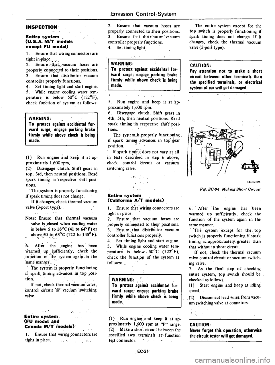
EC328A
Fig
EC
94
Making
Short
Circuit
6
After
ihe
engine
has
been
warmed
up
sufficiently
check
the
function
of
the
system
again
in
the
same
manner
The
system
except
for
the
top
switch
is
properly
fU
lctioning
if
spark
timing
is
approximately
greater
than
that
without
a
short
circuit
If
not
check
the
thermal
vacuum
valve
control
circuit
or
vacuum
switch
ing
valve
7
As
the
final
step
of
checking
entire
system
top
switch
should
be
checked
as
follows
1
Start
engine
and
keep
at
idling
speed
2
Disconnect
lead
wires
from
vacu
um
switching
valve
at
connetors
CAUTION
Never
forget
this
operation
otherwise
the
circuit
tester
will
get
damaged
Page 151 of 548
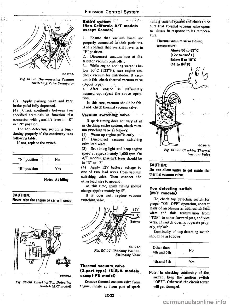
EC173A
Fig
EC
95
Disconnecting
Vacuum
Switching
Valve
Connector
3
Apply
parking
brake
and
keep
brake
pedal
fully
depressed
4
Check
continuity
between
two
specified
terminals
ai
function
test
connector
with
gearshift
lever
in
R
or
N
position
The
top
detecting
switch
is
func
tioning
properly
if
the
continuity
is
as
following
table
If
not
replace
the
switch
N
position
No
R
position
Yes
Note
At
idling
CAUTION
Never
race
the
engine
or
car
will
creep
r
q
EC329A
Fig
EC
96
Checking
Top
Detecting
Switch
Arr
model
Emission
Control
System
Entire
system
Non
California
AfT
models
except
Canada
1
Ensure
that
vacuum
hoses
are
properly
connected
to
their
positions
And
confirm
that
gearshift
lever
is
in
P
position
2
Disconnect
vacuum
hose
atdis
tributor
vacuum
controller
3
While
engine
cooling
wat
r
is
be
low
SOoC
1220F
race
engine
and
check
vacuum
for
distributor
If
vacu
um
is
felt
check
thermal
vacuum
valve
3
port
type
4
After
engine
is
sufficiently
warmed
up
repeat
the
above
opera
tion
In
this
case
vacuum
should
be
felt
If
not
check
thermal
vacuum
valve
Vacuu
m
switching
valve
If
spark
timing
does
not
vary
at
all
in
checking
entire
system
check
vacu
um
switching
valve
i
follows
I
Warm
up
engine
sufficiently
2
Disconnect
vacuum
switching
valve
lead
wires
3
Set
timing
light
and
keep
engine
speed
at
approximately
1
600
rpm
On
AfT
models
geaishiftlever
should
be
in
N
or
P
4
Apply
l2V
battery
voltage
to
one
of
two
lead
wires
from
vacuum
switching
valve
Then
connect
the
other
lead
wire
to
ground
At
this
time
spark
timing
should
change
appioximately
by
50
If
it
does
not
replace
vacuum
switching
valve
EC175A
Fig
EC
97
Checking
Vacuum
Switching
Valv
Thermal
vacuum
valve
3
port
type
U
s
A
models
except
FU
model
Remove
thermal
vacuum
valve
from
engine
Inhale
air
from
port
of
spark
EC32
timing
amttol
systetn
andcheck
to
sure
that
thermal
vacuum
valve
opens
or
closes
in
response
to
its
tempera
ture
Thermal
vacuum
walye
closing
temperature
Above
50
to
63
c
122
to
1450
F
Below
5
to
1SoC
41
to
64
Fl
J
EC161A
Fig
EC
98
Checking
Thermal
Vacuum
Valv
CAUTION
Do
not
allow
water
to
get
inside
the
thenna
vacuum
valve
Top
detecting
switch
M
T
models
To
check
top
detecting
switch
for
proper
ON
OFF
operation
contact
leads
of
an
ohmmeter
with
swiich
lead
wires
and
shift
transmiosion
from
TOP
to
other
forward
gear
and
vice
versa
If
switch
does
not
operate
prop
erly
replace
Continuity
of
top
detecting
switch
should
be
a
follows
Other
than
4th
and
5th
No
4th
and
5th
Yes
Note
In
checking
continuity
oCthe
switch
keep
the
ignition
switch
OFF
Otherwise
the
circuit
tester
will
get
damaged
Page 182 of 548

ASSEMBLY
To
assemble
reverse
the
order
of
disassembly
Carefully
observe
the
fol
lowing
instructions
CAUTION
B
tfore
installi
lg
IC
ignition
unit
make
sure
mating
surfaces
of
IC
ignition
unit
and
distriblitor
are
clean
and
free
from
dust
sand
and
moisture
Align
match
marks
so
that
parts
are
assembled
to
their
original
posi
tions
2
Ensure
that
reluctor
is
properly
oriented
when
installing
on
shaft
Al
ways
drive
in
roll
pin
with
its
slit
toward
the
outer
end
of
shaft
See
Fig
EE
64
Be
sure
to
use
a
new
roll
pin
DESCRIPTION
The
IC
ignition
unit
utilizes
a
semi
conductor
IC
device
and
is
mounted
on
the
side
surface
of
the
distributor
The
IC
ignition
unit
has
the
fol
lOwing
circuits
Spark
timing
signal
monitoring
circuit
This
circuit
detects
the
ignition
signal
sent
from
the
distributor
pick
up
coil
and
amplifies
the
signal
2
Lock
preventing
circuit
This
circuit
cuts
off
the
ignition
coil
primary
current
when
the
ignition
switch
is
ON
and
the
engine
is
sta
tionary
If
the
ignition
coil
primary
current
is
allowed
to
flow
under
such
condi
tions
excessive
current
will
be
drawn
because
of
low
internal
resistance
of
the
ignition
coil
Engine
Electrical
System
r
5
EE747
Fig
EE
64
Driuing
in
Roll
Pin
3
When
installing
pinion
on
shaft
be
sure
to
install
pinion
gear
correctly
to
position
where
it
was
installed
4
Apply
grease
to
the
top
of
rotor
shaft
as
required
5
Check
the
operation
of
governor
before
installing
distributor
on
engine
Ie
IGNITION
UNIT
This
can
result
in
an
abnormal
temperature
rise
in
the
ignition
coil
or
discharged
battery
These
malfunc
tions
can
be
prevented
by
this
lock
preventing
circuit
3
Duty
control
circuit
This
circuit
controls
the
ratio
of
the
ignition
coil
primary
current
ON
OFF
time
periods
in
one
cycle
of
ignition
operation
111is
is
equivalent
to
the
dwell
angle
of
the
conventional
point
type
dis
tributor
In
order
to
provide
high
performance
spark
ruing
over
a
wide
range
of
driving
speeds
this
duty
can
be
controlled
by
the
source
voltage
and
the
ambient
temperature
as
well
as
by
the
engine
rpm
4
Power
switching
circuit
This
circuit
is
used
to
make
or
break
directly
the
primary
circuit
cur
EE
24
6
Properly
eenterstatOr
and
reluc
tor
before
tightening
Standard
air
gap
0
3
to
0
5
mm
0
012
to
0
020
in
0
3
to
0
5
mm
0
012
to
0
020
in
Fig
EE
65
EE748
Air
Gap
7
Adjust
ignition
timing
after
distri
butor
is
installed
on
engine
rent
of
the
ignition
coil
5
Current
limiting
circuit
This
circuit
controls
the
current
value
so
that
excessive
current
will
not
flow
through
the
power
switching
cir
cuit
To
ensure
efficient
operation
of
the
IC
ignition
unit
these
five
circuits
are
manufactured
in
one
assembly
as
shown
in
Fig
EE
66
The
semi
conductor
IC
is
utilized
for
all
these
circuits
except
the
power
switching
circuit
The
power
switching
circuit
uses
one
power
transistor
and
the
circuit
is
arranged
on
the
ceramic
substrate
together
with
resislors
capa
citors
and
diodes
Each
component
part
of
this
unit
is
highly
reliable
however
should
any
part
be
found
faulty
the
entire
as
sembly
musl
be
replaced
Page 247 of 548

Manual
Transmission
SERVICE
DATA
AND
SPECIFICATIONS
GENERAL
SPECIFICATIONS
Transmission
model
F4W60L
FS5W60L
Item
No
of
speeds
4
5
Synchromesh
type
Warner
Shift
type
t
3
I
I
R
2
4
2
4
R
r
I
I
1
3
5
1st
3
513
3
513
2nd
2
170
2
170
3rd
1
378
1
378
Gear
ratio
4th
1
000
1
000
5th
0
846
Rev
3
764
3
464
Final
gear
ratio
3
700
3
700
155
13
6
15
13
4PR
16
5
Speedometer
Tire
155SRI3
16
5
gear
ratio
175
70SR13
16
5
Oil
capacity
liter
US
pt
Imp
pt
1
3
2
U
2
Y
I
1
2
2
i
i
i
MT31
Page 335 of 548
Front
Axle
Front
Suspension
SERVICE
DATA
AND
SPECIFICATIONS
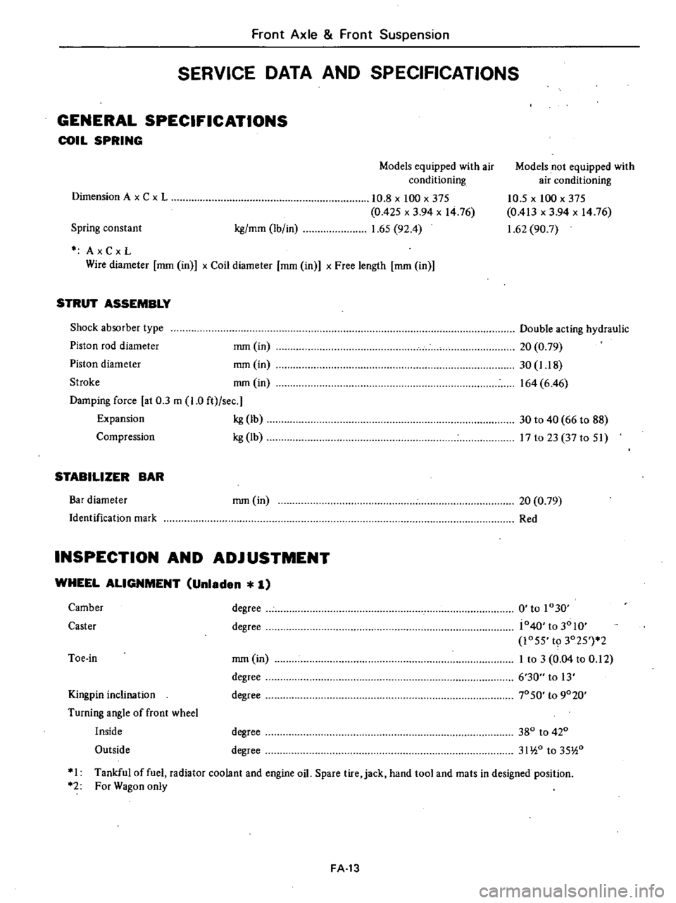
GENERAL
SPECIFICATIONS
COIL
SPRING
Models
equipped
with
air
conditioning
Models
not
equipped
with
air
conditioning
10
5
x
100
x
375
0
413
x
3
94
x
1476
1
62
90
7
Spring
constant
kg
mm
Ib
in
10
8
x
100
x
375
0
425
x
3
94
x
1476
1
65
92
4
Dimension
A
x
C
x
L
AxCxL
Wire
diameter
mm
in
x
Coil
diameter
mm
in
x
Free
length
mm
in
STRUT
ASSEMBLY
Shock
absorber
type
Piston
rod
diameter
mm
in
Piston
diameter
mm
in
Stroke
nun
in
Damping
force
at
0
3
m
1
0
ft
sec
Expansion
kg
Ib
Compression
kg
Ib
Double
acting
hydraulic
20
0
79
30
1
18
164
6
46
30
to
40
66
to
88
17
to
23
37
to
51
STABILIZER
BAR
Bar
diameter
Identification
mark
mm
in
20
0
79
Red
INSPECTION
AND
ADJUSTMENT
WHEEL
ALIGNMENT
Unladen
1
Kingpin
inclination
Turning
angle
of
front
wheel
Inside
Outside
mm
in
degree
degree
0
to
1030
j040
to
3010
1055
t9
3025
2
I
to
3
0
04
to
0
12
6
30
to
13
70
SO
to
9020
Camber
Caster
degree
degree
Toe
in
degree
degree
380
to
420
31
io
to
35
i0
I
Tankful
of
fuel
radiator
coolant
and
engine
oil
Spare
tire
jack
hand
tool
and
mats
in
designed
position
2
For
Wagon
only
FA
13
Page 354 of 548
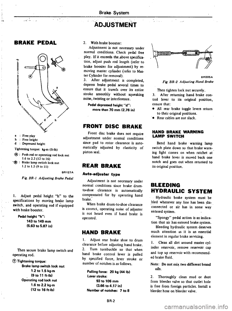
BRAKE
PEDAL
a
a
Fr
play
h
Free
height
d
Depressed
height
Tightening
torque
Icg
m
ft
tb
@
@
Push
rod
or
operating
rod
lock
nut
1
6
to
2
2
12
to
16
Brake
lainp
switch
lock
nut
1
2
to
I
5
9
to
11
BR121A
Fig
BR
1
Adjusting
Broke
Pedal
I
Adjust
pedal
height
h
to
the
specifications
by
moving
brake
lamp
switch
and
operating
rod
if
equipped
with
brake
booster
Pedal
height
h
143
to
149
mm
5
63
to
5
87
inl
Then
secure
brake
lamp
switch
and
operating
rod
C
l
Tightening
tOlque
Blake
lamp
witch
lock
nut
1
2
to
1
5
kg
m
9
to
11
ft
lb
Operating
lad
lock
nut
1
6
to
2
2
kg
m
12
to
16
ft
b
Brake
System
ADJUSTMENT
2
With
brake
booster
Adjustment
is
not
necessary
under
normal
conditions
Check
pedal
free
play
If
it
exceeds
the
above
specifica
tion
adjust
push
rod
length
refer
to
brake
booster
for
adjustment
by
re
moving
master
cylinder
rerer
to
Mas
ter
Cylinder
for
removal
3
After
adjustment
is
completed
depress
brake
pedal
several
times
to
ensure
that
it
travels
over
its
entire
stroke
smoothly
without
squeaking
noise
twisting
or
interference
Pedal
depr
d
Might
d
more
than
70
mm
2
76
in
FRONT
DISC
BRAKE
Front
disc
brake
does
not
require
adjustment
under
normal
conditions
since
pad
to
rotor
clearance
is
auto
malically
adjusted
by
elasticity
of
piston
seal
REAR
BRAKE
Auto
edJuster
type
Adjustment
is
not
necessary
under
normal
conditions
since
brake
drum
t
shoe
clearance
is
automatically
compensated
for
by
operating
hand
brake
Wlien
brake
drum
to
shoe
clearance
is
correct
operating
noise
of
adjuster
is
not
heard
even
if
hand
brake
is
operated
HAND
BRAKE
I
Adjust
rear
brake
shoe
to
drum
clearance
before
adjusting
hand
brake
2
Turn
turnbuckle
so
that
when
hand
brake
control
lever
is
pulled
by
specified
force
lever
stroke
or
number
of
notches
is
as
follows
Pulling
fOil
20
kg
44
Ib
lever
stroke
93
to
106
mm
3
66
to
4
17
in
Numbel
of
notches
7
to
8
BR
2
f
BAQ05A
Fig
BR
2
Adjusting
Hand
Brake
Then
tighten
lock
nut
securely
3
After
returning
hand
brake
con
trol
lever
to
its
original
position
ensure
that
e
All
rear
brake
toggle
levers
return
to
their
original
positions
Rear
cables
are
not
slack
HAND
BRAKE
WARNING
LAMP
SWITCH
Bend
hand
brake
warning
lamp
switch
plate
down
so
that
brake
warn
ing
light
comes
on
when
ratchet
at
hand
brake
lever
is
moved
back
one
notch
and
goes
out
when
returned
to
its
original
position
BLEEDING
HYDRAULIC
SYSTEM
Hydraulic
brake
system
must
be
bled
whenever
any
line
has
been
dis
connected
or
air
has
in
some
way
entered
system
Spongy
pedal
action
is
an
indica
tion
that
air
has
entered
brake
system
Bleeding
hydraulic
system
deserves
much
attention
as
it
is
an
essential
element
in
regular
brake
servicing
Clean
all
dirt
around
master
cyl
inder
reservoir
remove
reservoir
cap
and
top
up
reservoir
with
recommend
edbrake
fluid
Note
Do
not
mix
two
different
brand
oils
2
Thoroughly
clean
mud
or
dust
from
bleeder
valve
so
that
outlet
hole
is
free
from
foreign
particles
Install
a
bleeder
hose
on
bleeder
valve
Page 365 of 548

INSPECTION
Brake
drum
I
Check
inner
diameter
of
brake
drum
to
make
sure
it
is
properly
round
and
tapered
If
it
is
not
repair
or
replace
brake
drum
Inner
diameter
Standard
diametel
203
2
mm
8
in
Maximum
diameter
204
5
mm
8
05
in
Out
of
loundness
ellipticity
less
than
0
02
mm
0
0008
in
Radial
runout
less
than
0
1
mm
0
004
in
Total
indicator
reading
Taper
less
than
0
02
mm
0
0008
in
Measured
at
a
point
40
mm
1
57
in
flam
inlet
2
Contact
surface
with
which
lin
ings
come
into
contact
should
be
fine
finished
with
No
120
to
150
sandpaper
3
Using
a
drum
racer
finish
brake
drum
by
machining
if
it
shows
any
sign
of
score
marks
partial
wear
or
stepped
wear
on
its
contact
surface
Note
After
brake
drum
has
been
completely
re
conditioned
or
re
placed
check
drum
and
shoes
for
proper
contact
pattern
Brake
e
embly
1
Replace
any
linings
which
are
cracked
worn
or
oil
stained
2
If
lining
is
worn
to
less
than
the
specified
value
replace
Lining
wear
limit
Minimum
thickness
1
5
mm
0
059
in
3
Replace
any
shoe
return
springs
which
are
broken
or
fatigued
4
Replace
fatigued
anti
rattle
spring
damaged
pin
and
or
retainer
Wheel
cylinder
I
Replace
any
cylinder
or
piston
which
is
scratched
scored
or
worn
on
its
sliding
contact
surface
Brake
System
2
Replace
worn
parts
if
piston
to
cylinder
clearance
is
beyond
limit
Piston
ta
cylinder
clearance
less
than
0
15
mm
0
0059
in
3
Replace
any
piston
cup
which
is
worn
or
otherwise
damaged
4
Replace
if
contacting
face
of
cyl
inder
and
shoe
is
worn
locally
or
in
step
5
Replace
any
damaged
dust
cover
fatigued
piston
spring
or
faulty
thread
ed
parts
6
Replace
any
tube
connector
which
is
worn
on
its
threaded
portion
INSTALLATION
Install
rear
brake
in
reverse
order
of
removal
closely
observing
the
follow
ing
1
Tighten
following
parts
to
speci
fied
torque
CAUTION
When
installing
brake
tube
use
Flare
Nut
Torque
Wrench
6694310000
ifl
Tightening
torque
Flared
nut
1
5
to
1
8
kg
m
11
to
13
fHb
Ail
bleedel
0
7
to
0
9
kg
m
15
1
to
6
5
ft
Ib
Wheel
cylinder
mounting
bolt
0
6
to
0
8
kg
m
4
3
to
5
8
ft
b
2
There
are
two
types
of
adjusters
which
have
right
thread
or
left
thread
R
H
brake
Right
thread
adjuster
L
H
brake
Left
thread
adjuster
3
Sparingly
apply
a
coat
of
brake
grease
to
the
following
points
Lubricating
points
e
Adjuster
nut
and
rod
threads
Mating
surfaces
between
adjuster
and
toggle
lever
and
pin
and
roller
BR
ll
0
J
o
BR
117
A
Fig
BR
24
Lubricating
Points
of
Adju
ter
4
Referring
to
Fig
BR
25
for
locations
of
lubricating
points
apply
a
coat
of
brake
grease
to
these
points
Exercise
care
not
to
allow
grease
to
come
into
contact
with
lining
or
ad
juster
screws
Lubricating
points
e
Contact
areas
between
wheel
cyl
inder
anchor
block
and
brake
shoe
e
Mating
surfaces
between
brake
shoe
and
brake
disc
Contact
areas
between
hand
brake
adjuster
and
brake
shoe
Contact
areas
between
brake
disc
brake
shoe
and
toggle
lever
Contact
areas
between
anti
rattle
pin
spring
retainer
and
brake
shoe
Fig
BR
25
Lubricating
Points
5
To
prevent
water
from
entering
brake
drum
apply
dry
sealant
to
brake
disc
mounting
surfaces
of
the
follow
ing
parts
Wheel
cylinder
Anti
rattle
spring
6
Make
sure
that
entire
brake
shoe
fits
in
place
7
Make
sure
that
adjuster
operates
properly
8
After
installation
is
completed
check
and
adjust
shoe
to
drum
clear
ance
by
operating
hand
brake
several
times
9
Bleed
brake
system
Page 378 of 548
t
MAINTEN
NCE
TIRE
INFLATION
Correct
tire
pressure
is
very
impor
tant
for
steering
ease
and
riding
com
fort
Correct
pressure
also
makes
for
a
quieter
ride
and
extends
tire
life
If
all
tires
are
inspected
frequently
and
maintained
at
correct
pressure
any
sharp
objects
in
tread
can
be
quickiy
detected
nd
abnormal
wear
which
invites
serious
problems
can
be
avoided
After
inflating
tires
valves
should
be
checked
for
leakage
Without
valve
caps
leakage
will
occur
due
to
dirt
and
water
resulting
in
underinflation
Ac
cordingly
whenever
tire
pressure
is
checked
be
sure
to
tighten
vaive
caps
firmly
by
hand
JW
Sri
in
1
II
I
i
I
1
I
1
1
I
I
I
II
I
I
I
i
M
I
l
1
14
nl
01
I
II
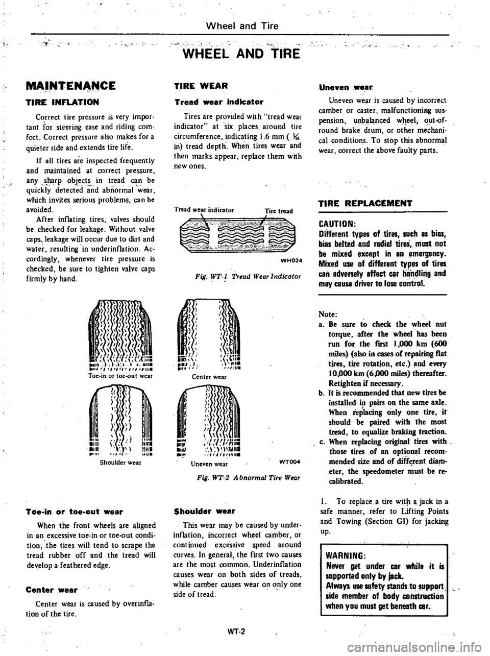
Toe
in
or
toe
out
wear
I
J
I
I
p
rt
i
Ilnl
lll
11111
IllIlI
Shoulder
wear
Toe
in
or
toe
out
wear
When
the
front
wheels
are
aligned
in
an
excessive
toe
in
or
toe
out
condi
tion
the
tires
will
tend
to
scrape
the
tread
rubber
off
and
the
tread
will
de
elop
a
feathered
edge
Center
wear
Center
wear
is
caused
by
overinfla
tion
of
the
tire
Wheel
and
Tire
WHEEL
AND
TIRE
TIRE
WEAR
Tread
ar
Indicator
Tires
are
provided
with
tr
lad
wear
indicator
at
six
places
around
tire
circumference
indicating
1
6
mm
J
in
tread
depth
When
tires
wear
and
then
marks
appear
replace
them
wtth
new
ones
Tread
wear
indicator
Tire
tread
L
1
c
WH024
Fig
WT
l
Tread
WearJndicator
n
1
ii
J
J
f
J
I
h
I
me
1111
Center
wear
j
I
1II
mnr
I
j
n
Ii
Ii
i
I
Jil
111
lie
Uneven
wear
WT004
Fig
WT
2
A
bnormal
Tire
Wtor
Shoulder
wear
This
wear
may
be
caused
by
under
inflation
incorrect
wheel
camber
or
continued
excessive
speed
around
curves
In
general
the
first
two
causes
are
the
most
common
Underinflation
causes
wear
on
both
sides
of
treads
while
camber
causes
wear
on
only
one
side
of
tread
WT
2
Uneven
wear
Uneven
wear
is
caused
by
incorrect
camber
or
caster
malfunctioning
sus
pension
unbalanced
wheel
out
of
round
brake
drum
or
other
mechani
cal
conditions
To
stop
this
abnormal
wear
correct
the
above
faulty
parts
TIRE
REPLACEMENT
CAUTION
Different
types
of
tires
sucb
as
bias
bias
belted
and
radial
tireS
must
not
be
mixed
except
in
an
emergancy
Mixed
use
of
different
types
of
tires
can
adversely
affect
car
ilndlilig
and
may
cause
driver
to
lose
control
Note
a
Be
sure
to
check
the
wheel
nut
torque
after
the
wheel
has
been
run
for
the
rust
I
000
km
600
miles
also
in
cases
of
repairing
fiat
tires
tire
rotation
etc
and
every
10
000
km
6
000
miles
thereafter
Retighten
if
necessary
b
It
is
recommended
that
new
tires
be
installed
in
pairs
on
the
same
axle
When
replacing
only
one
tire
it
should
be
paired
with
the
most
tread
to
equalize
braking
tl1lction
c
When
replacing
original
tires
with
those
tires
of
an
optional
recom
mended
site
and
of
diff
rent
diam
eter
the
speedometer
must
be
reo
calibrated
I
To
replace
a
tire
with
a
jack
in
a
safe
manner
refer
to
Lifting
Points
and
Towing
Section
GI
for
jacking
up
WARNING
Never
get
under
car
whila
it
is
supported
only
by
jack
Always
use
Il
fety
stands
to
suppon
side
member
of
body
construction
when
you
must
get
berreatb
car
Page 379 of 548
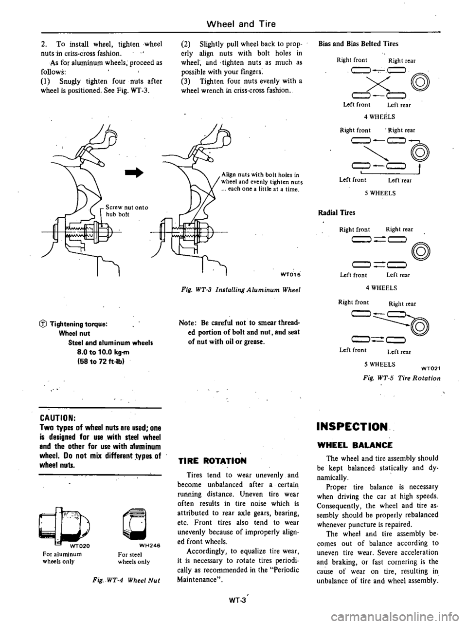
2
To
install
wheel
tighten
wheel
nuts
in
criss
cross
fashion
As
for
aluminum
wheels
proceed
as
follows
I
Snugly
tighten
four
nuts
after
wheel
is
positioned
See
Fig
WT
3
Iil
Tightening
torque
Wheel
nut
Steel
and
aluminum
wheels
8
0
to
10
0
kg
m
58
to
72
ft
Ibl
CAUTION
Two
types
of
wheel
nuts
Bre
used
one
is
designed
for
use
with
steel
wheel
Bnd
the
other
for
use
with
aluminum
wheel
Do
not
mix
different
types
of
wheel
nuts
p
WT020
For
aluminum
wheels
only
c
WH246
For
teel
wheels
only
Fig
WT
4
Wheel
Nut
Wheel
and
Tire
2
Slightly
pull
wheel
back
to
prop
erly
align
nuts
with
bolt
holes
in
wheel
and
tighten
nuts
as
much
as
possible
with
your
fingers
3
Tighten
four
nuts
evenly
with
a
wheel
wrench
in
criss
cross
fashion
f
WT016
Align
nuti
with
bolt
holes
in
wheel
and
evenly
tighten
nuts
each
one
a
little
at
a
time
Fig
WT
3
Installing
Aluminum
Wheel
Note
Be
careful
not
to
smear
thread
ed
portion
of
bolt
and
nut
and
seat
of
nut
with
oil
or
grease
TIRE
ROTATION
Tires
tend
to
wear
unevenly
and
become
unbalanced
after
a
certain
running
distance
Uneven
tire
wear
often
results
in
tire
noise
which
is
attributed
to
rear
axle
gears
bearing
etc
Front
tires
also
tend
to
wear
unevenly
because
of
improperly
align
ed
front
wheels
Accordingly
to
equalize
tire
wear
it
is
necessary
to
rotate
tires
periodi
cally
as
recommended
in
the
Periodic
Maintenance
WT
3
Bias
and
Bias
Belted
Tires
Right
front
Right
rear
c
J
c
l
X@
c
l
c
J
Left
front
Left
rear
4
WH
EELS
Right
front
Right
rear
c
J
c
l
@
9
c
J
Left
front
Left
rear
5
WHEELS
Radial
Tires
Right
front
Right
rear
c
J
c
l
@
c
l
c
J
Left
front
Left
rear
4
WHEELS
Right
front
Right
rear
c
J
c
J
c
l
Left
front
Left
rear
5
WHEELS
WT021
Fig
WT
5
Tire
Rotation
INSPECTION
WHEEL
BALANCE
The
wheel
and
tire
assembly
should
be
kept
balanced
statically
and
dy
namically
Proper
tire
balance
is
necessary
when
driving
the
car
at
high
speeds
Consequently
the
wheel
and
tire
as
sembly
should
be
properly
rebalanced
whenever
puncture
is
repaired
The
wheel
and
tire
assembly
be
comes
out
of
balance
according
to
uneven
tire
wear
Severe
acceleration
and
braking
or
fast
cornering
is
the
cause
of
wear
on
tire
resulting
in
unbalance
of
tire
and
wheel
assembly