automatic transmission fluid DATSUN 210 1979 Service Manual
[x] Cancel search | Manufacturer: DATSUN, Model Year: 1979, Model line: 210, Model: DATSUN 210 1979Pages: 548, PDF Size: 28.66 MB
Page 9 of 548

Erigine
crankcase
EI
gine
cooling
system
Transmission
case
Final
drive
case
housing
Steering
gear
box
Fuel
tank
Air
conditioning
system
Refrigerant
Compressor
oil
f
tl
It
J
4
i
1
protect
the
catalytic
cop
verter
froitr
contamination
t
n
General
Information
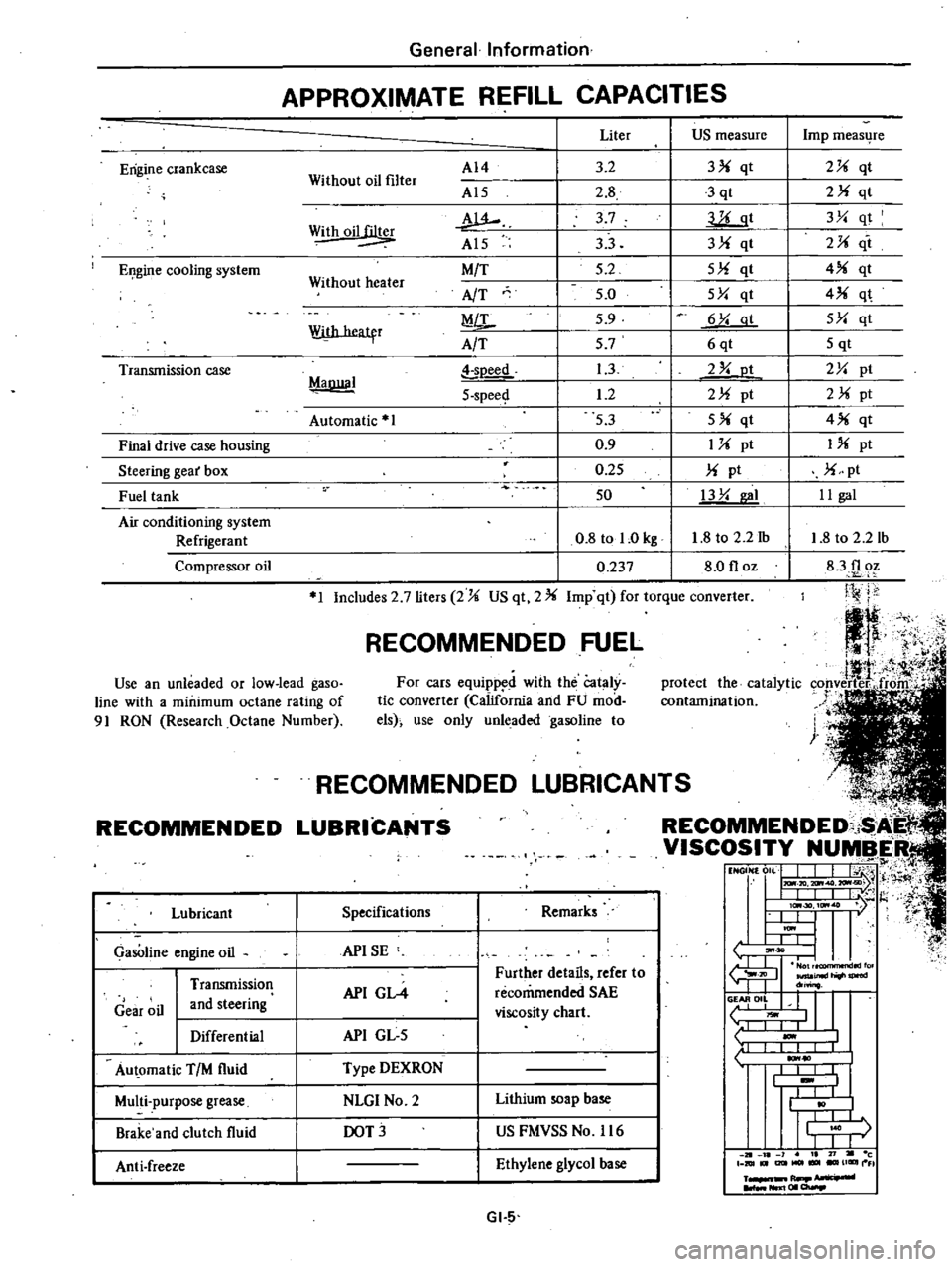
APPROXIMATE
REFILL
CAPACITIES
Without
oil
filter
AI4
Al5
w
Al5
M
T
AfT
MiL
A
T
Liter
US
measure
3
2
3
qt
2
8
3
qt
3
7
llLgt
33
3
qt
5
2
5
qt
5
0
5Y
qt
5
9
6
Y
at
57
6qt
1
3
2
Y
ot
1
2
2
pt
53
5
qt
0
9
1
pt
0
25
pt
50
13
Y
I
0
8
tol
Okg
1
8
to
2
2
1b
0
237
8
0
floz
Withoil
Without
heater
With
heatfr
MaDllal
soeed
5
spee
Automatic
1
1
Includes
2
7
liters
2
US
qt
2
Imp
qt
for
torque
converter
RECOMMENDED
FUEL
Use
an
unleaded
or
low
lead
gaso
line
with
a
minimum
octane
rating
of
91
RON
Research
Octane
Number
For
cars
equipp
d
with
the
Cataly
tic
converter
California
and
FU
mod
els
use
only
unleaded
gasoline
to
RECOMMENDED
Lubricant
GasOline
engine
oil
Gear
oil
Transmission
and
steering
Differential
Au
omatic
TIM
fluid
Multi
purpose
grease
Brake
and
clutch
fluid
Anti
freeze
L
NDED
LUBRICAN
COMMENDED
i
I
VISCOSITY
NUMBER
t1
NGON
0
L
J
I
j
H
I
IlL
I
t
l
I
lc
30
ItM
7
l
t
U
I
ItM
I
L
L
tJ
30
I
I
fu
JIl
inld
do
o
II
L
liOwl
1
I
I
1
10
I
I
I
I
t
I
I
j
r
I
I
J
1
21
l
1
I
71
c
DIUt
I2lItMOl
UGIIII
FI
R
NIl
I
01
a
Specifications
Remarks
APISE
API
GL4
Further
details
refer
to
recommended
SAE
viscosity
chart
API
GL
5
Type
DEXRON
NLGI
No
2
Lithium
soap
base
DOT
US
FMVSS
No
116
Ethylene
glycol
base
GI
5
Imp
meas4re
2
qt
2
qt
3Y
qt
2
it
4
qt
4
q
5Y
qt
5
qt
2Y
pt
2
pt
4
qt
I
pt
pt
II
gal
1
8
to
2
2
lb
83f1
oz
Ji
j
j
Page 149 of 548

gear
box
I
Disconnect
a
pair
of
lead
wires
2
Unscrew
the
switch
body
itself
The
switch
can
then
be
taken
out
3
Installation
is
in
the
reverse
se
quence
of
removal
dl
Tightening
torque
Top
cietectingswitch
2
0
to
3
0
kll
m
14
to
22
fHbl
@
EC892
Fig
EC
89
Remouing
Top
Detecting
Switch
Top
detecting
switch
For
AfT
models
The
top
detecting
switch
is
installed
on
the
side
face
of
the
gear
box
I
Disconnect
a
lead
wire
for
top
switch
2
Loosen
switch
itself
Switch
can
then
be
taken
out
Note
When
the
switch
is
remo
ed
automatic
transmission
fluid
flows
out
Prepare
some
rugs
to
prevent
the
fluid
rom
flowing
out
EC169A
Fig
EC
90
Remouing
Top
Detecting
Switch
An
models
3
Insta
tion
is
in
the
reverse
se
quence
of
removal
Emission
Control
System
dl
r
ingtorq
Top
detecting
switch
2
0
to
3
0
kll
m
14
to
22
ft
bl
Thermal
vacuum
valve
3
port
type
The
thermal
vacuum
valve
is
instal
led
on
the
rear
end
of
the
engine
cylinder
head
I
Drain
engine
coolant
about
one
liter
lUllS
qt
Ulmp
qt
2
Remove
manifold
nut
securing
heat
shi
eld
plate
r
l
EC170A
Fig
EC
91
Remouing
Hoot
Shield
Pwte
3
Disconnect
3
vacuum
hoses
and
unscrew
valve
itself
Valve
can
then
be
taken
out
4
Install
thermal
vacuum
valve
in
the
reverse
sequence
of
removal
At
this
time
the
valve
should
be
tighten
ed
to
a
tilt
angle
of
300
Note
Be
sure
to
apply
oealer
to
threads
o
the
valve
prior
to
instal
ling
new
valve
t
J
T1g11taning
torqUe
Thermal
cuum
waive
Less
than
2
2
kll
m
16
ft
bl
Manifold
nut
1
5
to
2
0kg
m
11
to
14
ft
bl
From
distributor
From
B
P
T
valve
From
air
cleaner
ECl71A
Fig
EC
92
mtalling
Thermal
Vacuum
Value
3
port
type
Vacl
ul11
delay
valVe
The
vacuum
delay
Valve
is
installed
on
the
midway
o
the
vacuum
tube
between
the
carburetor
and
distributor
vacuum
advance
mechanism
In
installing
the
valve
make
sure
that
the
brown
face
sid
is
connected
to
the
carburetor
side
Carburetor
sid
C
r
i
J
EG
30
Distributor
side
One
way
umbreDa
valve
Sintered
metal
disc
EC277
Fig
EC
93
In
tolling
Vacuum
Deloy
Value
Page 254 of 548

The
3N71
B
trammission
is
a
fully
automatic
unit
consisting
primarily
of
a
3
element
hydraulic
torque
converter
and
two
planetary
gear
sets
Two
multiple
disc
c1utclies
a
multiple
disc
brake
brake
band
and
one
way
clutch
provide
the
friction
elements
necessary
to
obtain
the
desired
function
of
the
two
planetary
gear
ets
A
hydraulic
control
system
is
used
to
operate
the
friction
elements
and
automatic
shift
controls
TORQUE
CONVERTER
The
torque
converter
is
attached
to
the
crankshaft
through
a
flexible
drive
plate
Heat
generat
in
the
t
rque
converter
is
dissipated
by
circulating
the
transmission
fluid
through
an
oil
to
water
type
cooler
in
the
radiator
lower
tank
The
welded
comtruction
of
the
torque
co
verter
prevents
di
3
ssembly
or
service
unless
highly
specialized
equipment
is
available
Qj
gJ
Autpmatic
Trimsmissi6n
DEScRIPTION
FLUID
RECOMMENDAnON
Use
DEXRON
type
automatic
transmission
fluid
only
IDENTIFICATION
NUMBER
Stamped
position
The
plate
is
attached
to
the
right
han
side
of
transmission
case
AT
M
Fig
AT
l
Identification
Number
Identification
of
number
arranaemanta
JAPAJllUTOIlATlC
TRAJISIIISSIO
C8
Ull
MODEL
X
0
12
3
NO
7
6
0
1
2
34
Number
designation
76
0
I
2
34
L
Serial
productioo
number
for
the
month
Month
of
production
1
Jan
2
Feb
X
Oct
Y
Nov
Z
Dec
Lut
IJgUre
denotins
the
year
A
D
IJ
III
J
W
f
r
lrr
G
1
Transmission
case
2
Oil
pump
3
Front
clutch
4
Band
brake
5
Rear
dutch
6
Front
planetary
geat
7
Rear
planetary
gear
8
One
way
clutch
9
Low
4
Reverse
brake
10
Oil
distributor
11
Governor
12
utput
shaft
13
Rear
extension
14
Oil
pan
IS
Control
valve
16
Input
shaft
17
Torque
converter
18
Converter
housi
19
Drive
pia
te
Tightening
torque
T
of
bolts
and
nuts
kg
m
ft
lb
@
T
4
to
5
29
to
36
@
T
14
to
16
101
to
116
@
T
4
5
to
5
5
33
to
40
@
T
0
6
to
0
8
4
3
to
5
8
@
T
0
5
to
0
7
3
6
to
5
1
T
2
0
to
2
5
14
to
18
@
T
1
3
to
1
8
9
to
13
@
T
0
55
ta
0
75
4
0
to
5
4
CD
T
0
25
to
0
35
1
8
to
2
5
AT312
Fig
AT
2
3N71B
Automatic
Trammiuion
AT
2
Page 255 of 548

Automatic
Transmission
HYDRAULIC
CONTROL
UNIT
AND
VALVES
The
hydraulic
or
a
tomatic
control
system
is
comprised
of
four
4
basic
groups
the
pressure
supply
system
the
pressure
regulating
system
the
flow
control
valves
and
the
friction
elements
PRESSURE
SUPPLY
SYSTEM
The
pressure
supply
system
consists
of
a
gear
type
oil
pwnp
driven
by
the
engine
through
the
torque
converter
The
pump
provides
pressure
for
aU
hydraulic
and
lubrication
needs
PRESSURE
REGULATOR
VALVES
The
pressure
regulating
valves
con
trol
the
output
pressure
of
the
oil
pump
Pre
ure
rellulator
valve
The
pressure
regulator
valve
con
trois
mainline
pressure
based
on
throttle
opening
for
the
operation
of
the
band
clutches
and
brake
Governor
valve
The
governor
valve
transmits
re
gulated
pressure
based
on
car
peed
to
the
shift
valves
to
control
upshifts
and
downshifts
Vacuum
throttle
valve
The
vacuum
throttle
valve
transmits
regulated
pressure
based
on
engine
load
vacuum
This
pressure
controls
the
pressure
regulator
valve
Also
this
pressure
is
applied
to
one
end
of
the
shift
valves
in
opposition
to
governor
pressure
which
acts
on
the
other
end
of
the
shift
valves
controlling
upshift
and
downshift
speeds
FLOW
CONTROL
VALVES
Manual
valve
The
manual
valve
is
moved
manual
Iy
by
the
car
operator
to
select
the
different
drive
ranges
1
2
ShHt
valve
The
1
2
shift
valve
automaticaIly
shifts
the
transmission
from
first
to
second
or
from
second
to
first
depend
ing
upon
governor
and
throttle
pres
sure
along
with
accelerator
position
solenoid
downshift
valve
See
Hy
draulic
Control
Circuits
Drive
2
2
3
ShHt
valve
The
2
3
shift
valve
automaticaIly
shifts
the
transmission
from
second
to
top
gear
or
from
top
to
second
de
pending
upon
governor
and
throttle
pressure
or
accelerator
position
sole
noid
downshift
valve
See
Hydraulic
Control
Circuits
Drive
3
Range
2
3
Tlmlnll
valve
For
2
3
shifts
a
restrictive
orifice
slows
the
application
fluid
to
the
front
clutch
while
the
slower
reacting
band
is
allowed
to
release
This
prevents
a
hard
2
3
or
3
2
shift
Under
heavy
load
however
the
engine
will
tend
to
run
away
during
the
2
3
or
3
2
shift
pause
therefore
a
2
3
timing
valve
using
throttle
and
governor
pressure
is
used
to
bypass
the
restrictive
orifice
during
such
heavy
load
conditions
Solenoid
down
hHt
valve
The
solenoid
downshift
valve
is
activated
electrically
when
the
ac
celerator
is
f1oor
d
causing
a
forced
downshift
from
top
to
second
top
to
first
or
second
to
first
gear
depending
upon
car
speed
governor
pressure
AT
3
Pre
ure
modified
valve
The
pressure
modifier
valve
assists
the
mainline
pressure
regulator
valve
in
lowering
mainline
pressure
during
high
speed
light
load
conditions
such
as
steady
speed
cruise
Governor
pres
sure
working
against
a
spring
opens
the
valve
which
aUows
modified
throt
tle
pressure
to
work
against
the
pres
sure
regulator
valve
spring
lowering
mainline
pressure
Lower
operating
pressure
under
light
load
reduces
oil
temperature
and
increases
transmis
sian
life
Throttle
back
up
valve
The
throttle
back
up
valve
assists
the
vacuum
throttle
valve
to
increase
line
pressure
when
the
manual
valve
is
shifted
either
to
2
or
I
range
Second
lock
valve
The
second
lock
valve
is
used
to
bypa
the
1
2
shift
valve
to
maintain
the
band
apply
pressure
in
2
posi
tion
The
valve
is
also
used
as
an
oil
passage
for
the
1
2
shift
valve
band
apply
pressure
in
D2
D3
and
12
Range
CLUTCHES
AND
BAND
SERVOS
The
servo
pistons
of
the
clutches
low
reverse
brake
and
band
are
moved
hydraulically
to
engage
the
clutches
brake
and
apply
the
band
The
clutch
and
brake
istons
are
released
by
spring
tension
and
band
piston
is
released
by
spring
tension
and
hy
draulic
pressure
Page 264 of 548

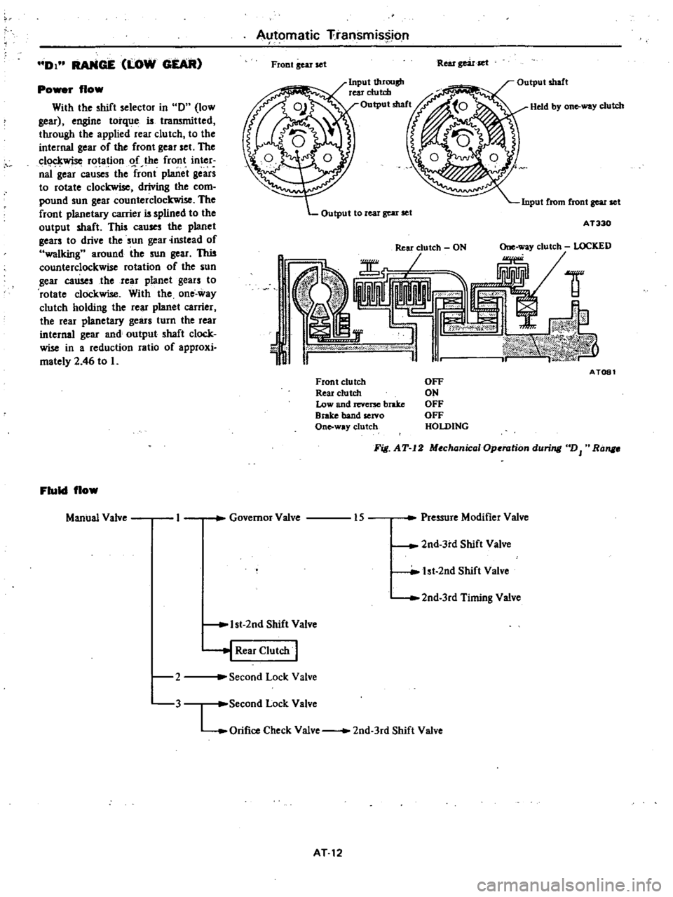
DI
RANGE
LOW
GEAR
Po
r
flow
With
the
shift
selector
in
0
low
gear
engine
torque
is
traJWnitted
through
the
applied
rear
clu
tch
to
the
internal
gear
of
the
front
gear
set
The
c1o
kwise
rotation
o
f
the
front
inter
naI
gear
causes
the
front
planet
gears
to
rotate
clockwise
driving
the
com
pound
sun
gear
counterclockwise
The
front
planetary
carrier
is
splined
to
the
output
shaft
This
cau
the
planet
gears
to
drive
the
sun
gear
instead
of
walking
around
the
sun
gear
This
counterclockwise
rotation
of
the
sun
gear
causes
the
rear
planet
gears
to
rotate
clockwise
With
the
one
way
clutch
holding
the
rear
planet
carrier
the
rear
planetary
gears
turn
the
rear
internal
gear
and
output
shaft
clock
wise
in
a
reduction
ratio
of
approxi
mately
2
46
to
L
Fluid
flow
Manual
Valve
2
3
Automatic
Transmission
Fiont
gear
set
Rear
gear
set
Input
t1uOllsh
rear
clutch
Output
shaft
Held
by
on
way
clutch
Input
from
front
gear
set
Output
to
real
gear
set
AT330
1
J
ld
AT081
Front
clutch
Reu
clutch
Low
and
revcrx
brake
Brake
band
servo
Onto
way
clutch
OFF
ON
OFF
OFF
HOLDING
Fig
AT
12
MochanicaIOp
rationduri
DJ
Ra
Governor
Valve
Pressure
Modifier
Valve
15
2nd
3rd
Shift
Valve
lst
2nd
Shift
Valve
2nd
3rd
Timing
Valve
1st
2nd
Shift
Valve
j
Rear
Clutch
I
Second
Lock
Valve
Second
Lock
Valve
LOrifice
Check
Valve
2nd
3rd
Shift
Valve
AT12
Page 268 of 548

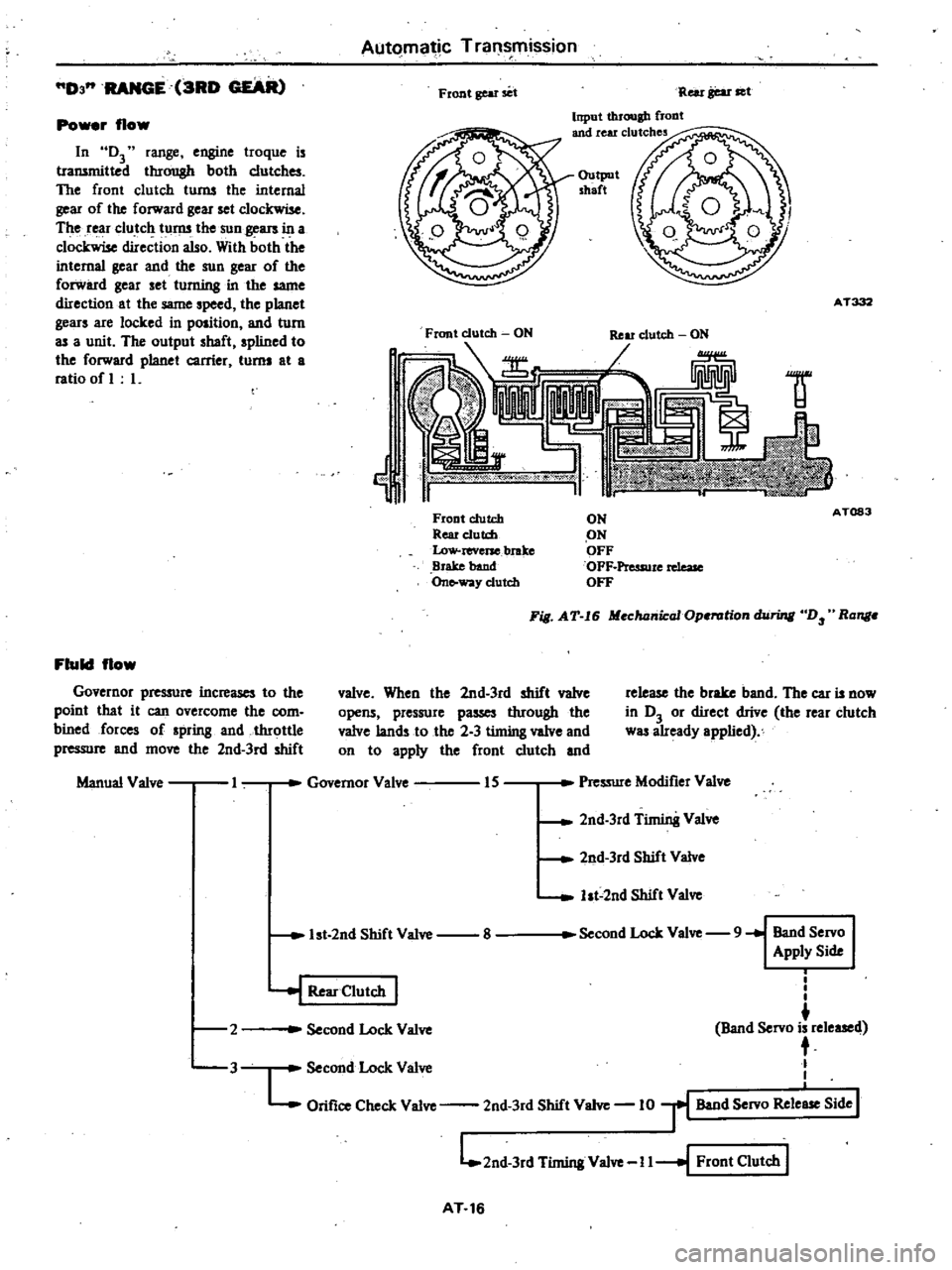
Automatic
Transmission
D3
RANGE
3RD
GEAR
Front
gear
set
Rei
r
gear
set
Input
through
flODt
and
rear
clutches
Power
flow
In
D3
range
engine
troque
is
transmitted
through
both
clutches
The
front
clutch
turns
the
internal
gear
of
the
forward
gear
set
clockwise
The
rear
clutch
turns
the
sun
gears
in
a
clockwise
direction
also
With
both
the
internal
gear
and
the
sun
gear
of
the
forward
gear
set
turning
in
the
same
direction
at
the
same
speed
the
planet
gears
are
locked
in
position
and
turn
as
a
unit
The
output
shaft
spIined
to
the
forward
planet
carrier
turns
at
a
ratio
of
L
Output
shaft
AT332
Front
clutch
ON
Ij
1f
Front
clutch
Rear
e1utd
Low
reverse
brake
Brake
band
On
way
clutch
ON
ON
OFF
OFF
Pressure
rdeaJe
OFF
A
T083
Fill
AT
I6
Mechanical
Operation
hiring
D
Ronge
Fluid
flow
Governor
pre
ure
increases
to
the
poinl
that
it
can
overcome
the
com
bined
forces
of
spring
and
throttle
pressure
and
move
the
2nd
3rd
shift
valve
When
the
2nd
3rd
shift
valve
opens
pressure
passes
through
the
valve
lands
to
the
2
3
timing
valve
and
on
to
apply
the
front
clutch
and
release
the
brake
band
The
car
is
now
in
D3
or
direct
drive
the
rear
clutch
was
already
applied
Manual
Valve
I
Governor
Valve
IS
Pressure
Modifier
Valve
2nd
3rd
Timin8
Valve
2nd
3rd
Shift
Valve
ht
2nd
Shift
Valve
1st
2nd
Shift
Valve
8
Second
Lock
Valve
9
Band
Servo
Apply
Side
2
i
I
I
Band
Servo
is
released
t
Second
Lock
Valve
L
Orifice
Check
Valve
2nd
3rd
Shift
Valve
10
r
Band
Servo
Rele
Side
I
L
2nd
3rd
Timing
Valve
I
I
I
Front
Clutch
I
J
Second
Lock
Valve
I
Rear
Clutch
I
3
AT
16
Page 272 of 548

Automatic
Transmission
2
RANGE
2ND
GEAR
The
range
2
position
is
used
to
lock
the
car
in
2nd
gear
preventing
upshifts
or
downshifts
under
any
con
ditions
Fluid
flow
opening
the
valVe
and
alloWing
pr
sure
to
p
into
the
line
of
the
throttle
valve
thus
assuring
adequate
throttle
pressure
even
during
decelera
tion
J
he
downshift
solenoid
valve
is
used
as
a
passage
for
line
pre
re
to
lock
the
1
2
and
2
3
shift
valves
Po
r
flow
Power
flow
in
2
raogo
is
the
same
as
in
D2
range
Uoe
pressure
from
the
manual
valve
opens
the
second
lock
valve
against
spring
pressure
As
this
valve
opens
pressure
the
passes
to
apply
the
band
servo
Une
pressure
also
flows
to
the
throttle
back
up
valve
UlllV
I
Governor
Valve
IS
Pressure
Modifier
Valve
2nd
3rd
Timing
Valve
2nd
3rd
Shift
Valve
1st
2nd
Shift
Valve
1st
2nd
Shift
Valve
j
Rear
Clutch
2
1
Band
Servo
Apply
Side
l
Solenoid
Downshift
Vilve
1312nd
3rd
Shift
Valve
1st
2nd
Shift
Valve
Second
Lock
Valve
9
4
Throttle
Back
up
Valve
17
Vacuwn
Throttle
Vilve
16
l
Jre
ModifJerVilve
2nd
3rd
Shift
Valve
2nd
3rd
Timing
Valve
Throttle
Drain
Valve
Pressure
Regulator
Valve
AT
20
Page 274 of 548

Automatic
Transmission
l
RANGE
LOW
AND
2ND
GEAR
second
12
afwvernor
preSsure
pre
vents
the
I
2
shift
valve
from
closing
The
range
1
position
is
used
to
lock
the
car
in
1st
gear
preventing
any
upshifts
If
the
selector
lever
is
moved
to
the
I
position
while
the
car
is
moving
at
high
speeds
the
transmis
sion
w
ill
not
shift
into
first
gear
until
car
speed
slows
to
approxiniately
55
km
h
35
mph
Instead
it
will
shift
to
Po
r
flow
The
power
flow
in
11
differs
slight
ly
from
01
in
that
the
low
and
reverse
band
is
applied
to
hold
the
rear
gear
set
planet
carrier
providing
engine
hraking
Power
flow
in
12
is
the
same
a
io02
Manual
Valve
Governor
Valve
15
Pressure
Modifier
Valve
I
Fluid
flow
Lolft
ar
Manual
pressure
passing
through
the
1
2
shift
valve
is
used
to
close
the
1
2
shift
valve
preventing
a
1
2
up
shift
Manual
pressure
pusing
through
the
downshift
valve
lock
the
2
3
siuit
valve
closed
along
with
applying
addi
tional
closing
pressure
to
the
I
2
shift
valve
2nd
3rd
Timing
Valve
2nd
3rd
Shift
Valve
lst
2ndSti
ft
Valve
1st
2nd
Shift
Valve
iRea
Clutcb
I
4
Solenoid
Downshift
Valve
13
I2nd
3rd
Shift
Valve
ht
2nd
Shift
Valve
Throttle
Back
up
Valve
5
C
1st
2nd
Shift
Valve
12
I
Throttle
Back
up
Valve
y
Low
Reverse
Bra1ce
I
Fluid
flow
2nd
ar
Manual
Valve
Governor
Valve
15
Preuurc
Modjfier
Valve
2nd
3rd
Timing
Valve
2nd
3rd
Shift
Valve
1st
2nd
Shift
Valve
8
1st
2nd
Shift
Valve
Second
Lock
Valve
9
I
Band
Servo
I
Apply
Side
4
t
Rear
Clutch
I
Solenoid
Downshift
Valve
13
I
2nd
3rd
Shift
Valve
ht
2nd
Shift
Valve
Throttle
Back
up
Valve
17
PreSlure
Modifier
Valve
2nd
3rd
Shift
Valve
2nd
3rd
Timing
Valve
Throttle
Drain
Valve
s
ht
2nd
Shift
Valve
Pressure
Regulator
Valve
AT
22
Page 278 of 548

4
Bolt
converter
to
drive
plate
Note
Align
chalk
mark
painted
a
cro5S
both
parts
during
disas
sembling
p
S
After
converter
is
installed
rotat
r
nkshait
veral
turns
and
check
to
be
sure
that
transmission
rotates
freely
without
binding
6
Pour
recommended
automatic
transmission
fluid
up
to
correct
level
through
oil
charge
pipe
7
Connect
manual
lever
to
shift
rod
Operation
should
be
carried
out
with
m
mual
and
selector
levers
in
N
8
Connect
inhibitor
switch
wires
Automatic
Transmission
NOte
a
Refer
to
page
AT40
for
Checking
and
Adjusting
Inhibitor
Switch
b
Inspect
end
edjust
switch
as
abo
whe
ever
it
has
to
be
removed
for
servi
e
9
Check
inhibitor
switch
for
op
eration
Starter
should
be
brought
into
op
eration
only
when
selector
lever
is
in
P
and
N
positions
it
should
not
be
started
when
lever
is
in
D
n
and
Ru
positions
Back
up
lamp
should
Iso
light
when
selector
lever
is
placed
in
R
position
10
Check
level
of
oil
in
transm
sion
For
detailed
procedure
see
page
AT39
AT
26
II
Move
selector
leve
through
all
positions
to
be
sure
that
transmission
operates
correctly
With
hand
brake
applied
rotate
engine
at
idling
Without
disturbing
the
above
seUlng
move
selector
lever
through
N
to
D
to
2
to
I
and
to
R
A
slight
shock
should
be
reU
by
handgripping
selector
each
time
transmission
is
shifted
Note
See
page
AT40
for
Checking
Engine
Idling
Revolution
12
Check
to
be
sure
that
line
pres
sure
is
correct
To
do
this
refer
to
page
AT
43
for
Line
Pressure
Test
13
Perform
stan
test
as
described
in
page
AT41
Page 284 of 548

Insp
ctIon
I
Check
for
signs
of
wear
or
dam
age
to
clutch
drive
plate
facing
If
found
worn
or
damaged
excessively
discard
Drive
plm
th
Standen
1
5
to
1
66mm
0
059
to
O
Inl
Allowable
limit
1A
mm
0
065
inl
2
Check
fOI
weer
on
snap
ring
and
for
weakened
or
broken
coil
spring
If
necessary
replace
with
new
ones
Spring
retainer
should
also
be
in
spected
fOI
warpage
sembi
1
Assembly
is
in
reverse
the
order
of
disassembly
Dip
all
parts
in
clean
automatic
transmission
fluid
before
installing
Fig
AT
56
l
ting
Clutch
PIlIte
2
After
clutch
is
a
embled
make
sure
th
t
clearance
between
snap
ring
CD
and
retaining
plate
V
is
held
within
specified
limits
If
necessary
lIy
with
other
retaining
plate
having
different
thickness
until
correct
clear
ance
is
obteined
S
1
deerence
1
6
to
2
0
mm
0
063
to
0
079
inl
Automatic
Transmission
Awilable
reteiningplate
Thickness
mm
in
10
6
0
417
10
8
0
425
11
0
0
433
11
2
0441
II
4
0
449
11
6
0
457
AT151
Fig
AT
67
Me
ring
Ring
to
PIlIte
Cleo
3
Testing
front
clutch
With
front
clutch
assembled
on
oil
pump
cover
direct
a
jet
of
air
into
hole
in
clutch
drum
for
definite
clutch
operation
AT152
Fig
AT
58
Taring
Front
Clutch
AT
32
REAR
a
UTCH
D1
mbl
AT313
1
Rear
clutch
drum
6
Snap
rina
2
Piston
7
SpriDa
3
Dished
plate
8
SDap
riJlI
4
Coil
sprina
9
Dri
plate
5
Rctainins
plate
10
Iltmm
plate
Fig
AT
59
Sectional
VielD
0
Rear
Clutch
1
Take
out
snap
ring
@
retaining
plate
@
drivc
plate
@
driven
plate
@
and
dished
plate
ID
Same
tech
nique
can
be
applied
as
in
disas
sembling
front
clutch
2
Remove
snap
ring
from
coil
spring
retainer
ST2S3200l
X
Fi6
AT
60
Remouing
SruJP
Ring