relay DATSUN 210 1979 Service Manual
[x] Cancel search | Manufacturer: DATSUN, Model Year: 1979, Model line: 210, Model: DATSUN 210 1979Pages: 548, PDF Size: 28.66 MB
Page 95 of 548
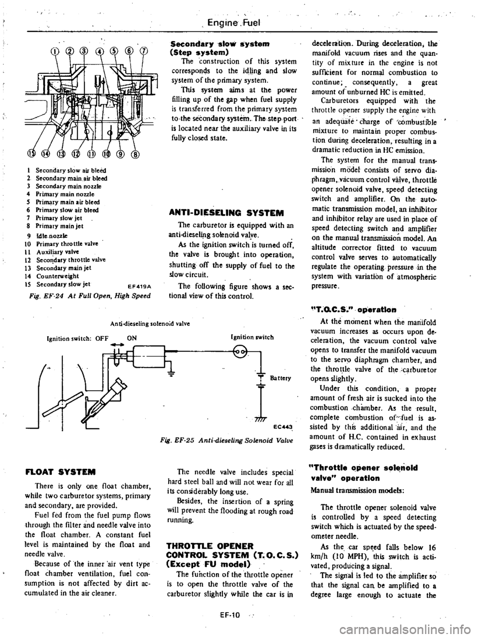
I
Secondary
slow
air
bleed
2
Secondary
main
air
bleed
3
Secondary
main
nozzle
4
Primary
main
nozzle
5
Primary
main
air
bleed
6
Primary
slow
air
bleed
7
Primary
slow
jet
8
Primary
main
jet
9
Idle
nozzle
10
Primary
throttle
valve
II
Auxiliary
valve
12
Seco
dary
throttle
valve
13
Secondary
main
jet
14
Counterweight
IS
Secondary
slow
jet
EF419A
Fig
EF
24
At
Full
Open
High
Speed
Engine
Fuel
Secondary
slow
system
Step
system
The
construction
of
this
system
corresponds
to
the
idling
and
slow
system
of
the
primary
system
This
system
aims
at
the
power
filling
up
of
the
gap
when
fuel
supply
is
transferred
from
the
primary
system
to
the
secondary
system
The
stepport
is
located
near
the
auxiliary
valve
in
its
fully
closed
state
ANTI
DIESELING
SYSTEM
The
carburetor
is
equipped
with
an
anti
liese1i
lg
solenoid
valye
As
the
ignition
switch
is
turned
off
the
valve
is
brought
into
operation
shutting
off
the
supply
of
fuel
to
the
slow
circuit
The
following
figure
shows
a
see
tional
view
of
this
control
An
ti
dies
eling
solenoid
valve
Ignition
switch
OFF
ON
t
L
li
FLOAT
SYSTEM
There
is
only
one
float
chamber
while
two
carburetor
systems
primary
and
secondary
are
provided
Fuel
fed
from
the
fuel
pump
flows
through
the
filter
and
needle
valve
into
the
float
chamber
A
constant
fuel
level
is
maintained
by
the
float
and
needle
valve
Because
of
the
inner
air
vent
type
float
chamber
ventilation
fuel
con
sumption
is
not
affected
by
dirt
ac
cumulated
in
the
air
cleaner
Ignition
switch
Q
1
T
Battery
niT
EC
3
Fig
EF
25
Anti
dieseling
Solenoid
Valve
The
needle
valve
includes
special
hard
steel
ball
and
wiD
not
wear
for
all
its
considerably
long
use
Besides
the
insertion
of
a
spring
will
prevent
the
flooding
at
rough
road
running
THROTTLE
OPENER
CONTROL
SYSTEM
T
O
C
S
Except
FU
model
The
function
of
the
throttle
opener
is
to
open
the
throttle
valve
of
the
carburetor
slightly
while
the
car
is
in
EF
10
deceleration
During
deceleration
the
manifold
vacuum
rises
and
the
quan
tity
of
mixture
in
the
engine
is
not
suffICient
for
normal
combustion
to
continue
4
consequently
a
great
amount
of
unburned
HC
is
emitted
Carburetors
equipped
with
the
throttle
opener
supply
the
engine
with
an
adequate
charge
of
combustible
mixture
to
maintain
proper
combus
tion
during
deceleration
resulting
in
a
dramatic
reduction
in
HC
emission
The
system
for
the
manual
trans
mission
model
consists
of
servo
dia
phragm
vlicuum
control
valve
throttle
opener
solenoid
valve
spee
l
detecting
switch
and
amplifier
On
the
auto
matic
transmission
model
an
inhibitor
and
inhibitor
relay
are
used
in
place
of
speed
detecting
switch
and
amplifier
on
the
manual
transmission
model
An
altitude
corrector
fitted
to
vacuum
control
valve
serves
to
automatically
regulate
the
operating
pressure
in
the
system
with
variation
of
atmospheric
pressure
T
o
C
S
n
operatIon
At
the
moment
when
the
manifold
vacuum
increases
as
occurs
upon
de
celeration
the
vacuum
control
valve
opens
to
transfer
the
manifold
vacuum
to
the
servo
diaphragm
chamber
and
the
throttle
valve
of
the
carburetor
opens
slightly
Under
this
condition
a
proper
amount
of
fresh
air
is
sucked
into
the
combustion
chamber
As
the
result
complete
combustion
of
fuel
is
as
sisted
by
this
additional
air
and
the
amount
of
H
C
contained
in
exhaust
gases
is
dramatically
reduced
Throttle
Clpener
sol
nold
valve
operation
Manual
transmission
models
The
throttle
opener
solenoid
valve
is
controlled
by
a
speed
detecting
switch
which
is
actuated
by
the
speed
ometer
needle
As
the
car
sp
ed
falls
below
16
km
h
10
MPH
this
switch
is
acti
vated
producing
a
signal
The
signal
is
led
to
the
amplifier
so
that
the
signal
can
be
amplified
to
a
degree
large
enough
to
actuate
the
Page 98 of 548
ELECTRIC
AUTOMATIC
CHOKE
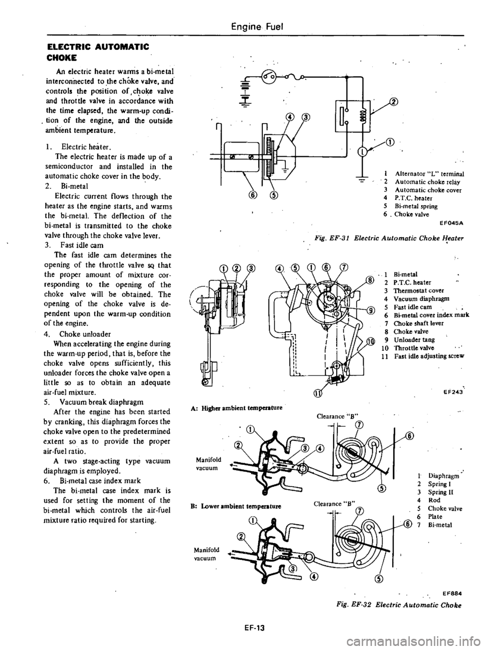
An
electric
heater
warms
a
bi
metal
interconnected
to
the
choke
valve
and
controls
the
position
of
c
oke
valve
and
throttle
valve
in
accordance
with
the
time
elapsed
the
warm
up
condi
tion
of
the
engine
and
the
outside
ambient
temperature
Electric
heater
The
electric
heater
is
made
up
of
a
semiconductor
and
installed
in
the
automatic
choke
cover
in
the
body
2
Bi
metal
Electric
current
flows
through
the
heater
as
the
engine
starts
and
warms
the
bi
metal
The
deflection
of
the
bi
metal
is
transmitted
to
the
choke
valve
through
the
choke
valve
lever
3
Fast
idle
cam
The
fast
idle
cam
determines
the
opening
of
the
throttle
valve
SQ
that
the
proper
amount
of
mixture
cor
responding
to
the
opening
of
the
choke
valve
will
be
obtained
The
opening
of
the
choke
valve
is
de
pendent
upon
the
warm
up
condition
of
the
engine
4
Choke
unloader
When
accelerating
the
engine
during
the
warm
up
period
that
is
before
the
choke
valve
opens
sufficiently
this
unloader
forces
the
choke
valve
open
a
little
so
as
to
obtain
an
adequate
air
fuel
mixture
S
Vacuum
break
diaphragm
After
the
engine
has
been
started
by
cranking
this
diaphragm
forces
the
choke
valve
open
to
the
predetermined
extent
so
as
to
provide
the
proper
air
fuel
ratio
A
two
stage
acting
type
vacuum
diaphragm
is
employed
6
Si
metal
case
index
mark
The
bi
metal
case
index
mark
is
used
for
selling
the
moment
of
the
bi
metal
which
controls
the
air
fuel
mixture
ratio
required
for
starting
Engine
Fuel
r
m
2
3
4
5
6
r
3
1
@
@
Alternator
L
terminal
Automatic
choke
relay
Automatic
choke
cover
P
T
C
heater
Bi
metaJ
spring
Choke
valve
Fig
EF
31
Electric
Automatic
Choke
l
eater
EF045A
l
A
Higher
ambient
temperature
Manifold
vacuum
Clearance
B
B
Lower
ambient
temperature
Clearance
Manifold
vacuum
1
Hi
metal
2
P
T
e
heater
3
Thermostat
cover
4
Vacuum
diaphragm
5
Fast
idle
earn
6
Bi
metal
cover
index
mark
7
Choke
shaft
lever
8
Choke
valve
9
Unloader
tang
10
Throttle
valve
11
Fast
idle
adjusting
screw
EF243
t
Diaphragm
2
Spring
I
3
Spring
11
4
Rod
5
Choke
valve
6
Plate
@
7
Bi
metal
EF884
Fig
EF
32
Electric
Automatic
Choke
EF
13
Page 101 of 548
CHOKEUNLOADER
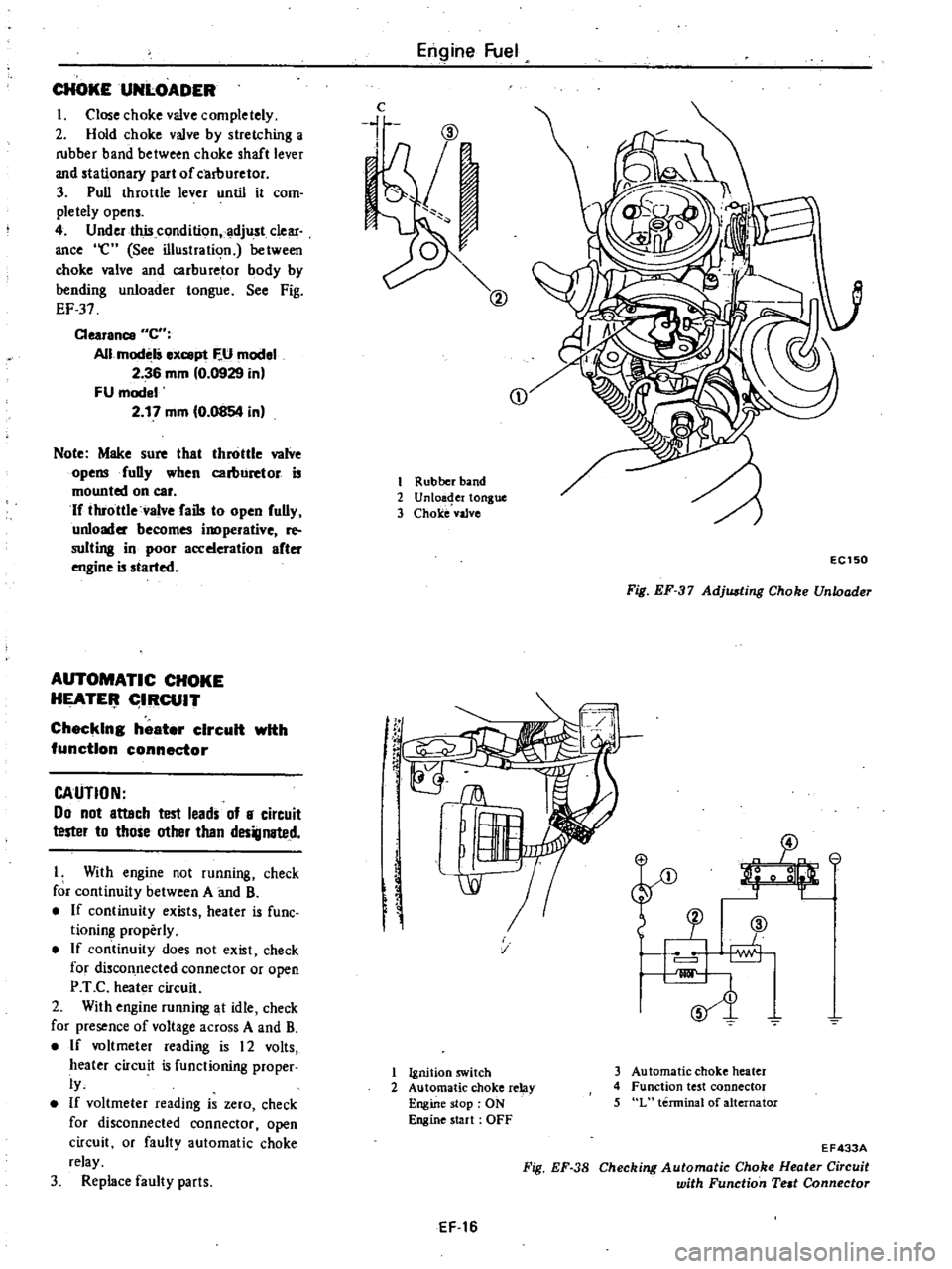
I
Close
choke
valve
completely
2
Hold
choke
valve
by
stretching
a
rubber
band
between
choke
shaft
lever
and
stationary
part
of
carllUretor
3
Pull
throttle
lever
until
it
com
pletely
opens
4
Under
this
condition
adjust
clear
ance
e
See
illustration
between
choke
valve
and
carburetor
body
by
bending
unloader
tongue
See
Fig
EF
37
Clearance
C
All
modelS
ex
pt
F
U
model
2
36
mm
0
0929
in
FU
model
2
17
mm
0
0854
in
Note
Make
sure
that
throttle
valve
opensfuDy
when
carburetor
is
mounted
on
car
If
throttle
valve
fails
to
open
fully
unloader
becomes
inoperative
re
suiting
in
poor
acceleration
after
engine
is
started
AUTOMATIC
CHOKE
HEATE
IRCUIT
Checking
heater
circuit
with
function
connector
CAUTION
00
not
attach
test
leads
of
8
circuit
tester
to
those
other
than
designated
I
With
engine
not
running
check
for
continuity
between
A
and
B
If
continuity
exists
heater
is
fune
tioning
properly
If
continuity
does
not
exist
check
for
discon
nected
connector
or
open
P
T
C
heater
circuit
2
With
engine
running
at
idle
check
for
presence
of
voltage
across
A
and
B
If
voltmeter
reading
is
12
volts
heater
circuit
is
functioning
proper
ly
If
voltmeter
reading
is
zero
check
for
disconnected
connector
open
circuit
or
faulty
automatic
choke
relay
3
Replace
faulty
parts
Engine
Fuel
c
i
CD
1
Rubber
band
2
Unloa
er
tongue
3
Choke
vaJve
f
rC
EC150
Fig
EF
37
Adjusting
Choke
Unloader
SJ
v
1
Ignition
switch
2
Automatic
choke
relay
Engine
stop
ON
Engine
start
OFF
3
Automatic
choke
heater
4
Function
test
connector
5
L
terminal
of
alternator
EF
16
Fig
EF
38
EF433A
Checking
Automatic
Choke
Heater
Circuit
with
Function
Teat
Connector
Page 102 of 548
AUTOMATIC
CHOKE
MECHANISM
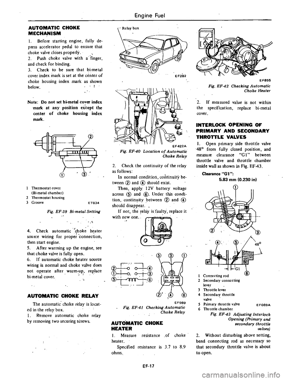
I
Before
starting
engine
fully
de
press
accelerator
pedal
to
ensure
that
choke
valve
closes
properly
2
Push
choke
valve
wi
th
a
finger
and
check
for
binding
3
Check
to
be
sure
that
bi
metal
cover
index
mark
is
set
at
the
center
of
choke
housing
index
mark
as
shown
below
I
Note
Do
not
set
b
metal
cover
index
mark
at
any
position
except
the
center
of
choke
housing
index
mark
CD
@
Thermosta
t
covel
Bi
metal
chamber
2
Thermostat
housing
3
Groove
E
T034
Fig
EF
39
Bi
metal
Setting
4
Check
automatic
choke
heater
source
wiring
for
proper
connection
then
start
engine
S
After
warming
up
the
engine
see
that
choke
valve
is
fully
open
6
If
automatic
choke
heater
source
wiring
is
normal
and
choke
valve
does
not
operate
after
warm
up
replace
bi
metal
cover
AUTOMATIC
CHOKE
RELAY
The
automatic
choke
relay
is
local
ed
in
the
relay
box
I
Remove
automatic
choke
relay
by
removing
two
securing
screws
Engine
Fuel
II
EF422A
Fig
EF
40
Location
of
Automatic
Choke
Relay
2
Check
the
continuity
of
the
relay
as
follows
In
normal
condition
continuity
be
tween
CV
and
@
should
exist
Then
apply
l2V
battery
voltage
across
CID
and
@
Under
this
condi
tion
contin
ity
between
CV
and
@
should
disappear
If
not
the
relay
is
faulty
replace
it
W
hWO
CID
CD
CV
o
0
@
Q
I
o
r
@
CID
@
EF989
Fig
EF
41
Checking
Automatic
Choke
Relay
AUTOMATIC
CHOKE
HEATER
I
Measure
resistance
of
choke
heater
Specified
resistance
is
3
7
to
8
9
ohms
EF
17
EF855
Fig
EF
42
Checking
Automatic
Choke
Heater
2
If
measured
value
is
not
within
the
specification
replace
bi
metal
cover
INTERLOCK
OPENING
OF
PRIMARY
AND
SECONDARY
THROTTLE
VALVES
1
Open
primary
side
throttle
valve
480
from
fully
closed
position
and
measure
clearance
G
1
between
throttle
valve
and
throttle
chamber
inside
wall
as
shown
in
Fig
EF
43
Clearance
6G1
5
83
mm
0
230
in
@
J
3
480
r
mit
GI
6
1
Connecting
rod
2
Secondary
connecting
lever
3
Throttle
lever
4
Secondary
throttle
valve
5
Primary
throttle
valve
6
Throttle
chamber
Fig
EF
43
Adjusting
Interlock
Opening
Primary
and
lecondary
throttle
values
2
Without
disturbing
above
setting
bend
connecting
rod
as
necessary
so
that
secondary
throttle
valve
is
about
to
open
E
F089A
Page 162 of 548
Engine
Electrical
System
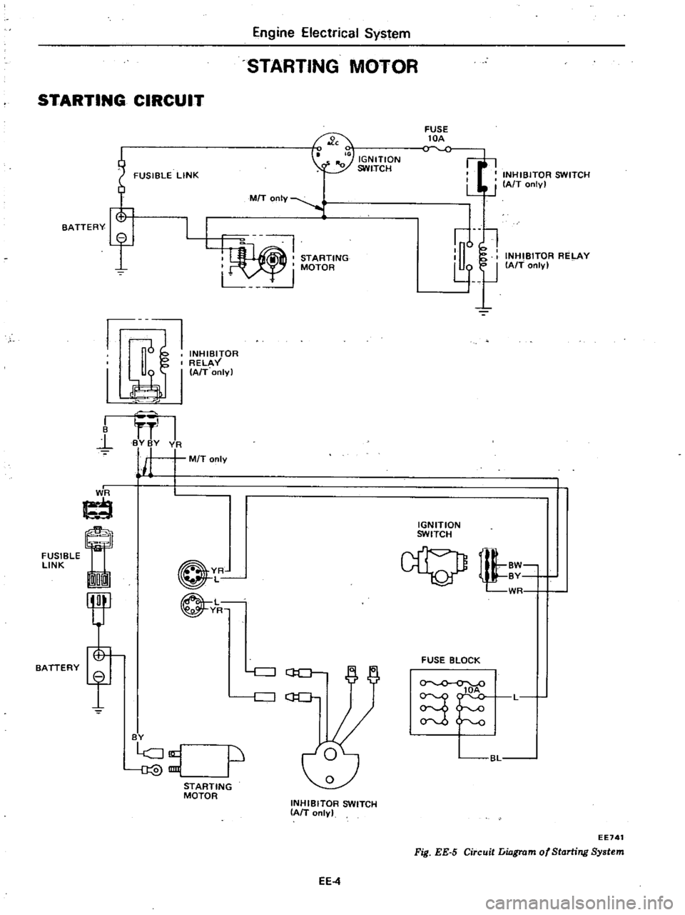
STARTING
MOTOR
STARTING
CIRCUIT
FUSIBLE
LINK
FUSE
lOA
INHIBITOR
SWITCH
LJ
J
IAfT
onlv
I
IGNITION
SWITCH
7
MIT
OnIY
STARTING
I
MOTOR
L
u
l
l
lJ
INHIBITOR
RELAY
IAfT
only
BATTERY
f
1J
INHIBITOR
RELAY
I
I
A
T
onlyl
I
B
l
I
BY
BY
VA
j
M
T
only
I
J
ti
FUSIBLE
LINK
On
IGNITION
SWITCH
BATTERY
YR
L
L
YR
tl
WR
FUSE
BLOCK
c
J
GO
c
J
C
lOA
S
L
BY
p
BL
STARTING
MOTOR
INHIBITOR
SWITCH
IAIT
only
EE741
Fig
EE
5
Circuit
Liagrom
of
Starting
System
EE4
Page 170 of 548
FUSIBLE
LINK
FUSIBLE
LINK
f
BATTERY
@@
V
R
@@
G
G
FUSleLE
ImrnI
LI
NK
MTI
I
En
g
n
l
Electrical
Syst
lOl
IGNITION
SWITCH
FUSE
lOA
o
v
FUSE
lOA
C
V
L@@
BAT
f
L
S
BI
I
I
sl
fRO
L
I
I
F
I
EI
i
K
a
ALTERNATOR
lE
Ie
VOLTAGE
REGULATOR
I
I
L
WR
I
1
d
I
t
J
t
IGNITION
WR
SWITCH
BW
U
0
AUTO
CHOKE
RELAY
G
1
WR
J
I
00
00
gg
1
00
VR
1
E
lDID
I
@
O
BAT
mID
W
J
WR
W
FUSE
BLOCK
CHARGE
WARNING
LAMP
5J
BL
Note
@
V
@
California
models
Non
Qilifomo
18
models
FU
models
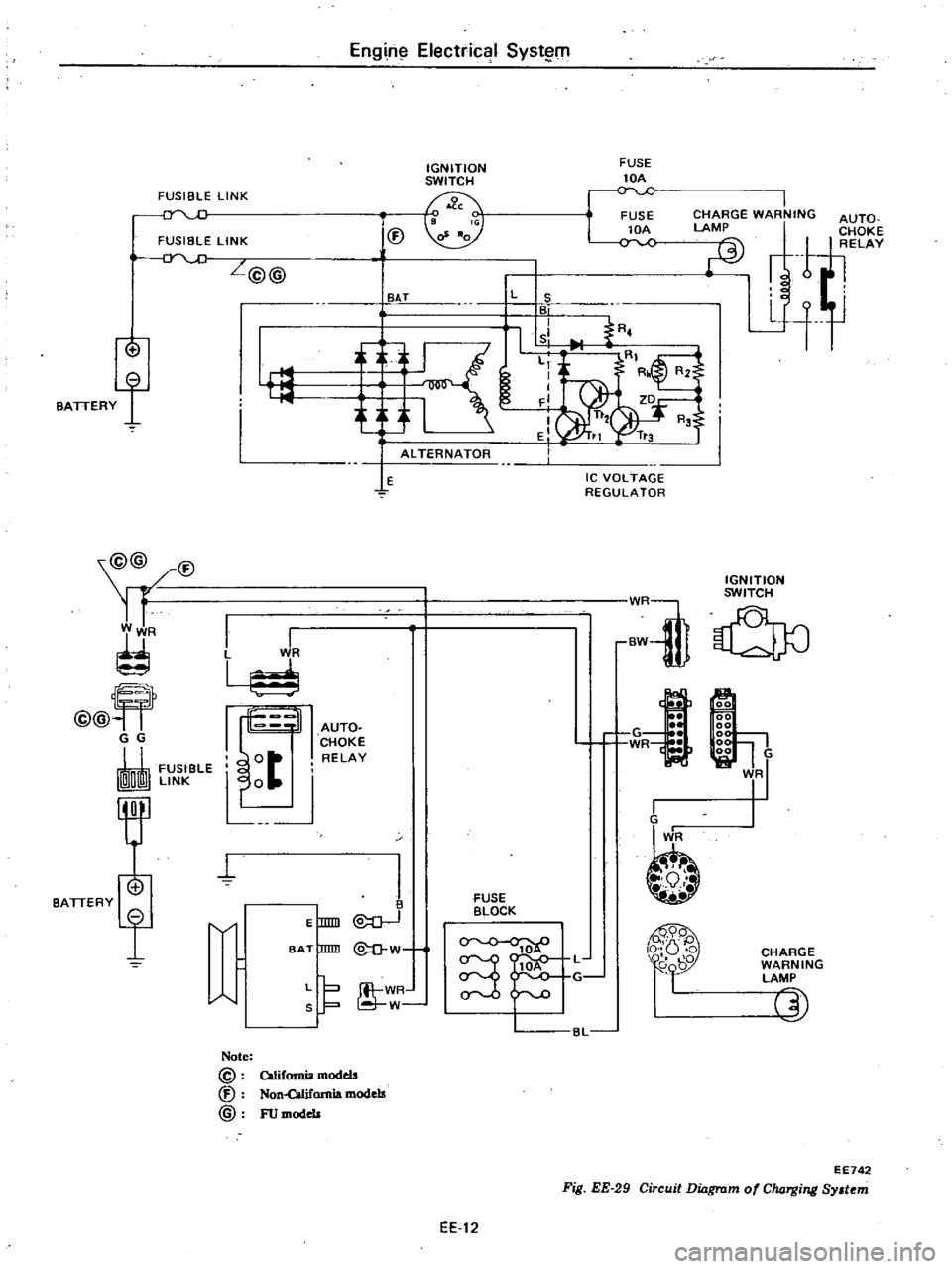
Fig
EE
29
Circuit
Dinrswr
EE742
mofCIuJ
Tg
ng
Sy
t
m
EE
12
Page 176 of 548
DESCRIPTION
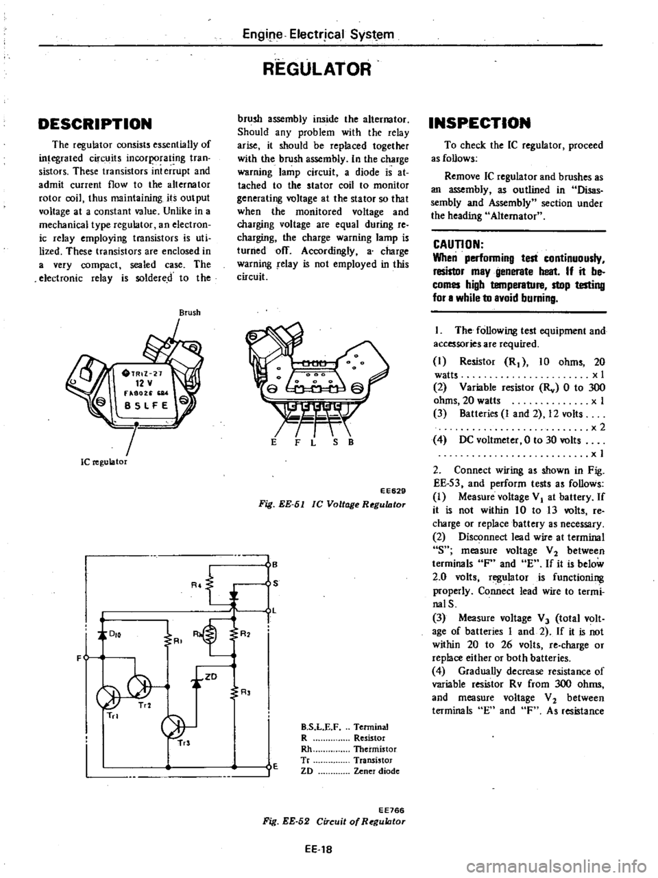
The
regulator
consists
essentially
of
in
egrated
circuits
incorporating
tran
sistors
These
transistors
int
errupt
and
admit
current
flow
to
the
alternator
rotor
coil
thus
maintaining
its
output
voltage
at
a
constant
value
Unlike
in
a
mechanical
type
regulator
an
electron
ic
relay
employing
transistors
is
uti
lized
These
transistors
are
enclosed
in
a
very
compact
sealed
case
The
electronic
relay
is
soldered
to
the
Brush
Ie
regulator
R
J
DIO
F
i
ZD
Tn
Engipe
Electrjcal
Syst
em
REGULATOR
brush
assembly
inside
the
alternator
Should
any
problem
with
the
relay
arise
it
should
be
replaced
together
with
the
brush
assembly
In
the
charge
warning
lamp
circuit
a
diode
is
at
tached
to
the
stator
coil
to
monitor
generating
voltage
at
the
stator
so
that
when
the
monitored
voltage
and
charging
voltage
are
equal
during
re
charging
the
charge
warning
lamp
is
turned
off
Accordingly
a
charge
warning
relay
is
not
employed
in
this
circuit
s
r
t
E
F
L
S
B
EE629
Fig
EE
51
lC
Voltage
RegultJtor
I
B
S
L
I
R
R
E
B
S
L
E
F
Terminal
R
Resistor
Rh
Thermistor
Tr
Transistor
ZD
Zener
diode
EE766
Fig
EE
52
Circuit
of
RegultJtor
EE
18
INSPECTION
To
check
the
IC
regulator
proceed
as
follows
Remove
IC
regulator
and
brushes
as
an
assembly
as
outlined
in
Disas
sembly
and
Assembly
section
under
the
heading
Alternator
CAUTION
When
performing
test
continuously
resistor
may
generate
heat
If
it
be
comes
high
temperature
stop
testing
for
a
while
to
avoid
burning
The
following
test
equipment
and
accessories
are
required
I
Resistor
R
10
ohms
20
watts
x
I
2
Variable
resistor
Rv
0
to
300
ohms
20
watts
x
I
3
Batteries
I
and
2
12
volts
x2
4
DC
voltmeter
0
to
30
volts
x
I
2
Connect
wiring
as
shown
in
Fig
EE
S3
and
perform
tests
as
follows
I
Measure
voltage
VI
at
battery
If
it
is
not
within
10
to
13
volts
re
charge
or
replace
battery
as
necessary
2
Disconnect
lead
wire
at
terminal
s
measure
voltage
V
2
between
terminals
F
and
E
If
it
is
below
2
0
volts
regulator
is
functioning
properly
Connect
lead
wire
to
termi
nalS
3
Measure
voltage
V
3
total
volt
age
of
batteries
I
and
2
If
it
is
not
within
20
to
26
volts
re
charge
or
replace
either
or
both
batteries
4
Gradually
decrease
resistance
of
variable
resistor
Rv
from
300
ohms
and
measure
voltage
V
2
between
terminals
En
and
F
As
resistance
Page 446 of 548
DATSUN
210
Model
8310
Series
SECTIONBE
BODY
ELECTRICAL
SYSTEM
CONTENTS
BODY
ELECTRICAL
WIRING
DESCRIPTION
FUSE
AND
FUSIBLE
LINK
WIRING
WIRING
HARNESS
LOCATION
OF
ELECTRICAL
UNIT
ELECTRICAL
UNIT
OF
LIGHTING
SYSTEM
BULB
SPECIFICATIONS
REMOVAL
AND
INSTALLATION
For
lamp
IGNITION
SWITCH
COMBINATION
SWITCH
ILLUMINATION
CONTROL
UNIT
AIMING
ADJUSTMENT
ELECTRICAL
UNIT
OF
SIGNAL
SYSTEM
BE
12
TURN
SIGNAL
SWITCH
BE
12
HORN
RELAY
BE
12
HAZARD
SWITCH
BE
12
STOP
LAMP
SWITCH
BE
12
BACK
UP
LAMP
SWITCH
BE
12
DOOR
SWITCH
BE
12
METERS
AND
GAUGES
BE
13
COMBINATION
METER
BE
13
TACHOMETER
BE
14
FUEL
LEVEL
AND
WATER
TEMPERATURE
INDICATOR
SYSTEM
BE
14
WARNING
SYSTEM
BE
15
CHARGE
WARNING
SYSTEM
BE
15
BRAKE
WARNING
SYSTEM
BE
15
BE
2
BE
2
BE
2
BE
4
BE
5
BE
8
BE
9
BE
9
BE
10
BE
10
BE
10
BE
11
BE
11
OIL
PRESSURE
WARNING
SYSTEM
SEAT
BELT
WARNING
SYSTEM
ELECTRICAL
ACCESSORIES
WINDSHIELD
WIPER
AND
WASHER
REAR
WINDOW
WIPER
AND
WASHER
CIGARETTE
LIGHTER
RADIO
CLOCK
REAR
WINDOW
DEFOGGER
STARTING
SYSTEM
For
automatic
transmission
models
HEATER
DESCRIPTION
AIR
FLOW
REMOVAL
AND
INSTALLATION
ADJUSTING
HEATER
CONTROL
DISASSEMBLY
AND
ASSEMBLY
OF
HEATER
UNIT
INSPECTION
WIRING
DIAGRAMS
AND
TROUBLE
DIAGNOSES
ELECTRICAL
SYSTEM
BLOCK
DIAGRAM
FUSE
BLOCK
CIRCUIT
SUPPLY
ROUTING
LIGHTING
SYSTEM
SIGNAL
SYSTEM
METERS
AND
GAUGES
WARNING
SYSTEM
ELECTRICAL
ACCESSORY
SYSTEM
HEATER
BE
15
BE
15
BE
17
BE
17
BE
18
BE
20
BE
20
BE
21
BE
21
BE
23
BE
23
BE
23
BE
24
BE
26
BE
27
BE
27
BE
28
BE
29
BE
29
BE
30
BE
31
BE
36
BE
41
BE
44
BE
4B
BE
55
Page 450 of 548
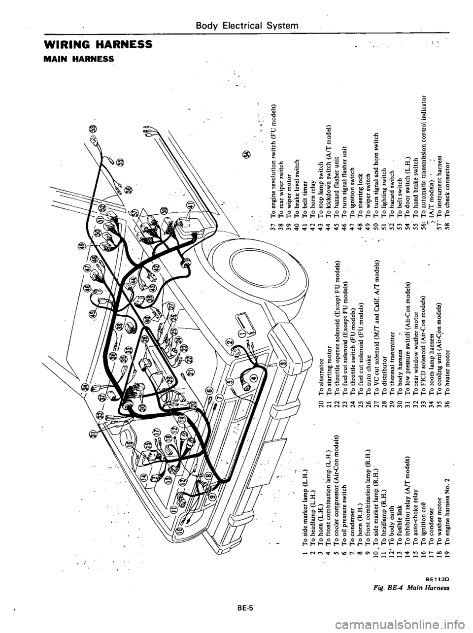
m
c
n
to
l
l
I
g
iF
0
1
To
side
marker
lamp
L
H
2
To
headlamp
L
H
3
To
horn
L
H
4
To
front
combination
lamp
L
H
5
To
cooler
co
pressor
Air
Con
models
6
To
oil
pressure
switch
7
To
condenser
8
To
horn
R
H
9
To
front
combination
la
t11p
R
H
10
To
side
marker
lamp
R
H
11
To
headlamp
R
H
12
To
body
earth
13
To
fusible
link
14
To
inhibitor
relay
AfT
model
15
To
aut6
choke
relay
16
To
ignition
coil
17
To
condenser
18
To
washer
motor
19
To
engine
harness
No
2
@
20
To
alternator
21
To
starting
motor
22
To
throttle
opener
solenoid
Except
FU
models
23
To
fuel
cut
solenoid
Except
FU
models
24
To
throttle
switch
FU
models
25
To
fuel
cut
solenoid
FU
models
26
To
auto
choke
27
To
VC
cut
solenoid
M
T
and
Calif
AfT
models
28
To
distributor
29
To
thermal
transmitter
30
To
body
harness
31
To
low
pressure
switcn
Air
Con
models
32
To
rear
window
washer
motor
33
To
FICO
solenoid
Air
Con
models
34
To
room
lamp
harness
35
To
cooling
unit
Air
C
on
models
36
To
heater
motor
37
To
engine
revolution
switch
FU
models
38
To
rear
wiper
switch
39
To
wiper
motor
40
To
brake
level
switch
41
To
belt
timer
42
To
horn
relay
43
To
stop
lamp
switch
44
To
kickdown
switch
AfT
model
45
To
hazard
flasher
unit
46
To
turn
signal
flasher
unit
47
To
ignition
switch
48
To
steering
lock
49
To
wiper
switch
50
To
turn
signal
and
hC
rn
switch
51
To
lighting
switch
5i
To
hazard
switch
53
To
belt
switch
54
To
door
switch
L
H
55
To
hand
brake
switch
56
To
automatic
transmission
control
indicator
AfT
models
57
To
instrument
harness
58
To
check
connector
I
0
i
a
z
Z
G
z
tIl
tIl
a
Z
Il
I
to
o
Co
m
16
n
n
OJ
1
3
Page 453 of 548
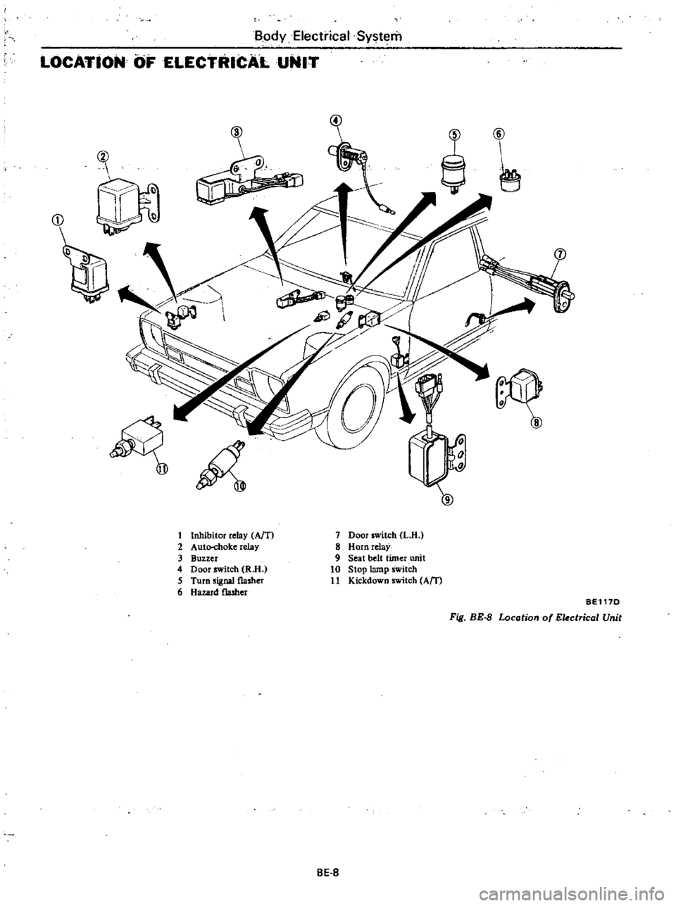
BodyElecti
ical
System
LOCATiON
OF
ELECTRICAL
UNIT
@
Q
J
r
J
D
t
Inhibitor
relay
AfT
2
Auto
chok
e
relay
3
Buzzer
4
Door
switch
RlI
5
Turn
signal
flasher
6
Hazard
flasher
7
Door
switch
L
H
8
Horn
relaY
9
Seat
belt
timer
unit
10
Stop
lamp
switch
11
Kickdown
switch
Am
BEl17D
Fig
BE
8
Locotiono
Ekctricol
Unit
BE
S