height adjustment DATSUN 210 1979 Service Manual
[x] Cancel search | Manufacturer: DATSUN, Model Year: 1979, Model line: 210, Model: DATSUN 210 1979Pages: 548, PDF Size: 28.66 MB
Page 51 of 548
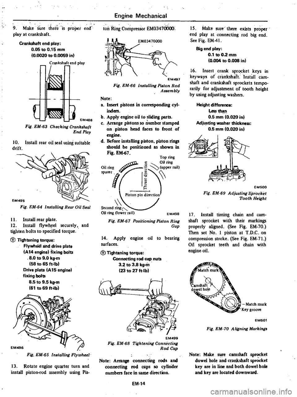
9
Make
SUre
there
is
proper
end
play
at
crankshaft
Crankshaft
end
play
0
05toO
15mm
0
OO20
to
0
0059
in
laJlk
h
end
play
J
EM486
Fig
EM
63
Checking
Crank
luJft
End
Play
10
Install
rear
oil
seal
using
suitable
drift
Fig
EM
64
n
talling
Rear
Oil
Seal
II
Install
rear
plate
12
Install
flywh
el
secwely
and
tighten
bolts
to
specified
torque
dl
Tightening
torque
Flywheel
and
drive
plate
A
14
engine
fixing
bolts
8
0
to
9
0
kg
m
58
to
65
ft
Ib
Drive
plate
A
15
engine
fixing
bolts
8
5
to
9
5
kg
m
61
to
69
ft
b
Fig
EM
65
n
talling
Flywheel
13
Rotate
engine
quarter
turn
and
install
piston
rod
assembly
using
Pis
Engine
Mechanical
ton
Ring
Compressor
EM03470000
EM497
Fig
EM
66
tolling
Platon
Rod
Assem
bly
Note
a
Insert
pistons
in
L
r
nding
cyl
inders
b
Apply
engine
oil
to
sliding
parts
c
Arrange
pistons
so
number
stamped
on
piston
head
faces
to
front
of
engine
d
Before
installing
piston
piston
rings
should
be
positioned
as
shown
in
Fig
EM
67
Second
ring
Oil
ring
lower
rail
EM49B
Fig
EM
67
Positioning
Piston
Ring
Gap
14
Apply
engine
oil
to
bearing
surfaces
dl
Tighte
ning
torque
Connecting
rod
cap
nuts
3
2
to
3
8
kg
m
23
to
27
ft
b
EM499
Fig
EM
68
Tightening
Connecting
Rod
Cap
Note
Am11
connecting
rods
and
connecting
rod
caps
so
cylinder
numben
face
in
same
direction
EM
14
I
S
Make
sure
there
exists
proper
end
play
at
connecting
rod
big
end
See
Fig
EM41
Big
end
play
0
1
to
0
2
mm
0
004
to
0
008
in
16
Insert
crank
sprocket
keys
in
keyways
of
crankshaft
Install
cam
shaft
and
crankshaft
sprockets
tempo
rarily
for
adjustment
of
tooth
height
by
using
adjusting
washers
Height
dif
Less1
h
l11
0
5
mm
0
020
in
Adjusting
washer
thickness
0
5
mm
10
020
in
EM500
Fig
EM
69
Adju
ting
Sprocket
Tooth
Height
17
Install
tinting
chain
and
cam
shaft
sprocket
with
their
markings
properly
aligned
See
Fig
EM
70
Then
set
No
I
piston
at
T
D
C
on
compression
stroke
See
Fig
EM
71
Oil
sprocket
teeth
and
chain
with
engine
oil
Match
mark
Key
groove
EM501
Fig
EM
70
Aligning
Markinga
Note
Make
sure
camshaft
sprocket
dowel
hole
and
crankshaft
sprocket
key
are
in
line
and
both
dowel
hole
and
key
are
located
downward
Page 56 of 548
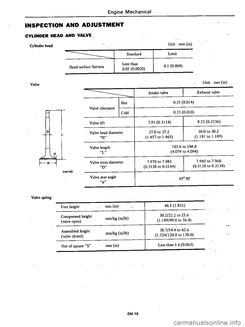
Engine
Mechanical
INSPECTION
AND
ADJUSTMENT
CYLINDER
HEAD
AND
VALVE
Cylinder
head
Unit
mm
in
Standard
Limit
Head
surface
flatness
Less
than
0
05
0
0020
0
1
0
004
Valve
Unit
mm
in
j
I
Hot
Valve
clearance
I
Cold
Intake
valve
Exhaust
valve
0
35
0
014
0
25
0
010
Valve
lift
7
91
0
3114
8
22
0
3236
H
37
0
to
37
2
1
457
to
1
465
30
0
to
30
2
1
181
to
1
189
D
L
Valve
head
diameter
a
H
Valve
length
L
103
6
to
104
0
4
079
to
4
094
D
7
970
to
7
985
0
3138
to
0
3144
7
945
to
7
960
0
3128
to
0
3134
Valve
stem
diameter
EM769
Valve
seat
angle
a
45030
Valve
spring
Free
height
mm
in
46
5
1
831
Compressed
height
mm
kg
in
lb
30
2
22
2
to
25
6
valve
open
1
189
49
0
to
56
4
Assembled
height
mm
kg
in
lh
38
7
544
to
62
6
valve
closed
1
524
120
0
to
138
0
Out
of
square
S
mm
in
Less
than
1
6
0
063
EM
19
Page 203 of 548
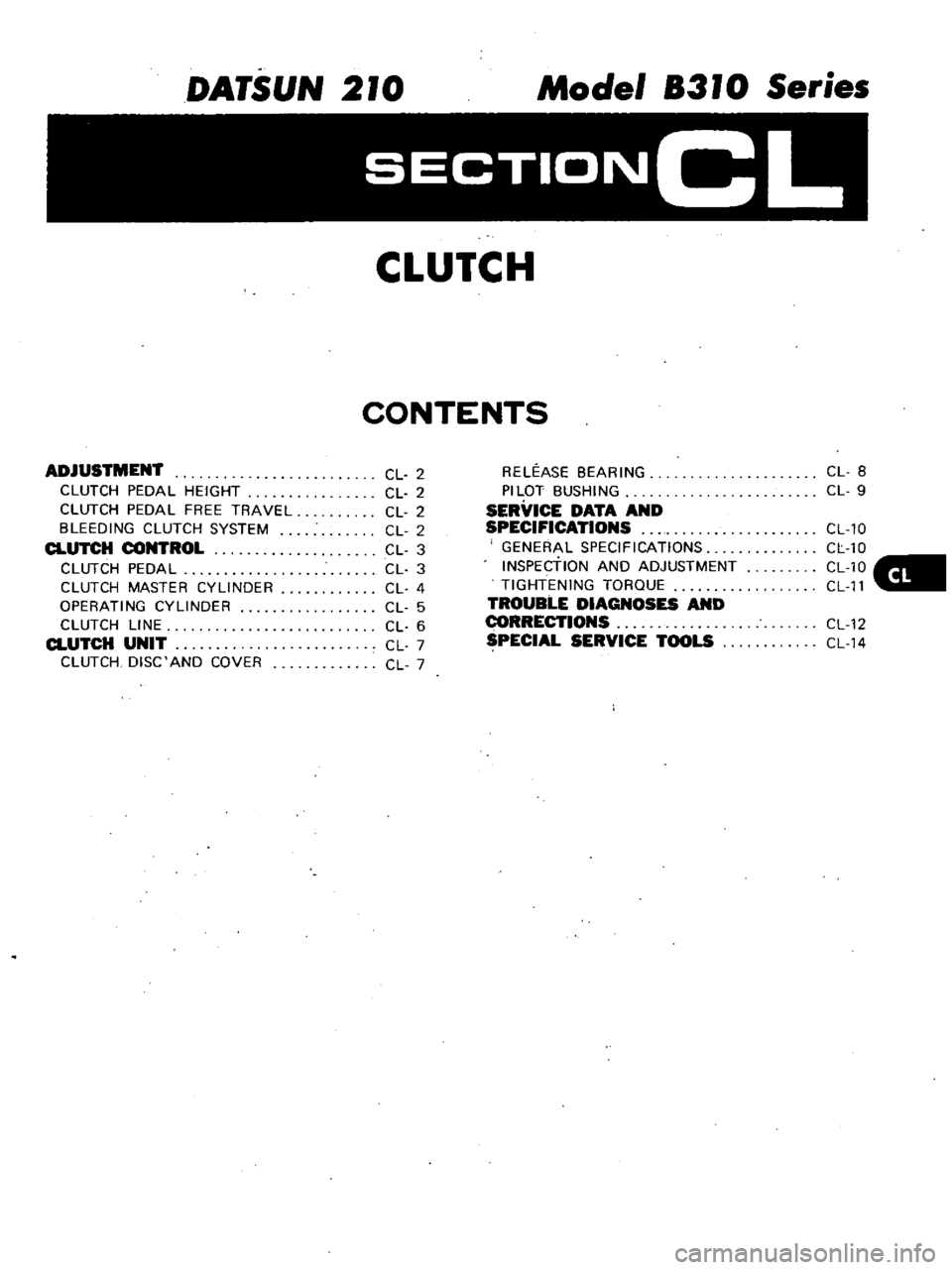
DATSUN
210
Model
8310
Series
SECTIONCL
CLUTCH
CONTENTS
ADJUSTMENT
CLUTCH
PEDAL
HEIGHT
CLUTCH
PEDAL
FREE
TRAVEL
BLEEDING
CLUTCH
SYSTEM
CLUTCH
CONTROL
CLUTCH
PEDAL
CLUTCH
MASTER
CYLINDER
OPERATING
CYLINDER
CLUTCH
LINE
CLUTCH
UNIT
CLUTCH
DISC
AND
COVER
CL
2
CL
2
CL
2
CL
2
CL
3
CL
3
CL
4
CL
5
CL
6
CL
7
CL
7
RELEASE
BEARING
PILOT
BUSHING
SERVICE
DATA
AND
SPECIFICATIONS
GENERAL
SPECIFICATIONS
INSPEctiON
AND
ADJUSTMENT
TIGHTENING
TORQUE
TROUBLE
DIAGNOSES
AND
I
ECTIONS
SPECIAL
SERVICE
TOOLS
CL
8
CL
9
CL
10
CL
10
CL10
CL
11
CL
12
CL
14
Page 204 of 548
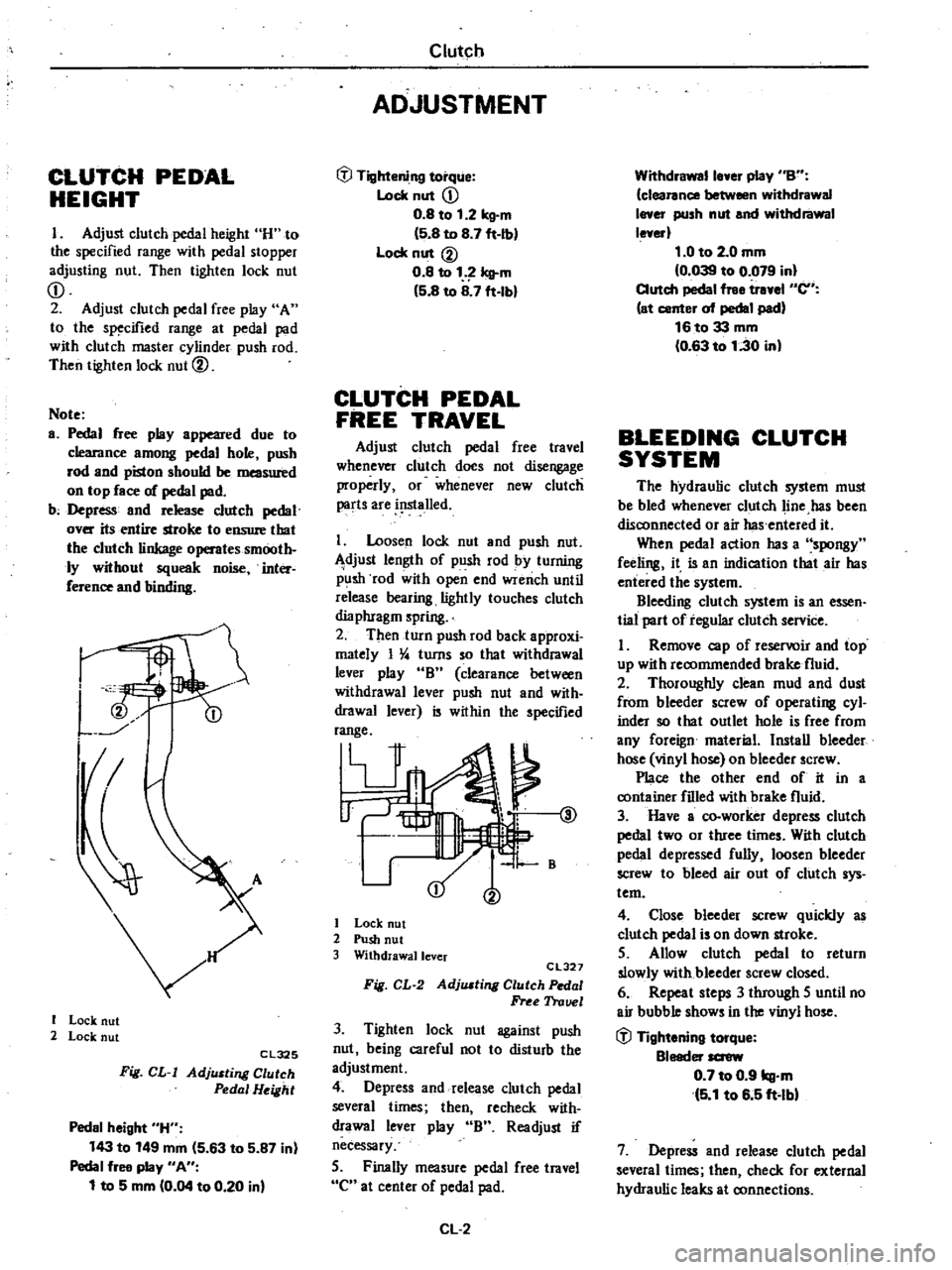
CLUTCH
PEDAL
HEIGHT
I
Adjust
clutch
pedal
height
H
to
the
specified
range
with
pedal
stopper
adjusting
nut
Then
tighten
lock
nut
CD
2
Adjust
clutch
pedal
free
play
A
to
the
specified
range
at
pedal
pad
with
clutch
master
cylinder
push
rod
Then
tighten
lock
nut
@
Note
a
Pedal
free
play
appeared
due
to
clearance
among
pedal
hole
push
rod
and
piston
should
be
measured
on
top
face
of
pedal
pad
b
Depress
and
release
clutch
pedal
over
its
entire
stroke
to
ensure
that
the
clutch
linkage
operates
smooth
ly
without
squeak
noise
inter
ference
and
binding
I
I
Lock
nut
2
Lock
nut
Cl325
Fig
CL
I
AdjlUting
Clutch
Pedal
Height
Pedal
height
H
143
to
149
mm
5
63
to
5
87
in
Pedal
free
play
An
1
to
5
mm
0
04
to
0
20
in
Clutch
ADJUSTMENT
tfl
Tightening
torque
Lock
nut
CD
0
8
to
1
2
kg
m
5
8
to
8
7
ft
Ib
Lock
nut
@
0
8
to
1
Icll
m
5
8
to
8
7
ft
lbl
CLUTCH
PEDAL
FREE
TRAVEL
Adjust
clutch
pedal
free
travel
whenever
clutch
does
not
disengage
properly
or
whenever
new
clutch
parts
are
i
lslalled
I
Loosen
lock
nut
and
push
nut
djust
length
of
push
rod
by
turning
p
lsh
rod
with
open
end
wrench
until
release
bearing
lightly
touches
clutch
dia
phragm
spring
2
Then
turn
push
rod
back
approxi
mately
I
4
turns
so
that
withdrawal
lever
play
B
clearance
between
withdrawal
lever
push
nut
and
with
drawal
lever
is
within
the
specified
range
V
@
1
B
I
Lock
nut
2
Push
nut
3
Withdrawallcver
CL327
Fig
CL
2
AdjlUting
Clutch
Pedal
Free
Trauel
3
Tighten
lock
nut
against
push
nut
being
careful
not
to
disturb
the
adjustment
4
Depress
and
release
clutch
pedal
several
times
then
recheck
with
drawal
lever
play
B
Readjust
if
necessary
5
Finally
measure
pedal
free
travel
C
at
center
of
pedal
pad
CL
2
Withdrawalle
er
play
nBn
clearance
between
withdrawal
I
er
push
nut
and
withdrawal
le
erl
1
0
to
2
0
mm
0
039
to
0
079
in
Clutch
pedal
free
tr
el
en
at
center
of
pedal
pad
16to33
mm
0
63
to
1
30
in
BLEEDING
CLUTCH
SYSTEM
The
hydraulic
clutch
system
must
be
bled
whenever
clutch
line
has
been
disconnected
or
air
has
entered
it
When
pedal
action
has
a
spongy
feeling
it
is
an
indication
that
air
has
entered
the
system
Bleeding
clutch
system
is
an
essen
tial
part
of
regular
clutch
service
I
Remove
cap
of
reservoir
and
top
up
with
recommended
brake
fluid
2
Thoroughly
clean
mud
and
dust
from
bleeder
screw
of
operating
cyl
inder
so
that
outlet
hole
is
free
from
any
foreign
material
Install
bleeder
hose
vinyl
hose
on
bleeder
screw
Place
the
other
end
of
it
in
a
container
filled
with
brake
fluid
3
Have
a
co
worker
depress
clutch
pedal
two
or
three
times
With
clutch
pedal
depressed
fully
loosen
bleeder
screw
to
bleed
air
out
of
clutch
sys
tem
4
Close
bleeder
screw
quickly
as
clutch
pedal
is
on
down
stroke
5
Allow
clutch
pedal
to
return
slowly
with
bleeder
screw
closed
6
Repeat
steps
3
through
5
until
no
air
bubble
shows
in
the
vinyl
hose
tfl
Tightening
torque
Bleeder
screw
0
7
to
0
9
kg
m
5
1
to
6
5
ft
lbl
7
Depress
and
release
clutch
pedal
several
times
then
check
for
external
hydraulic
leaks
at
connections
Page 207 of 548
are
clean
and
free
from
foreign
matter
Cearance
between
cylinder
bore
and
piston
Leu
than
0
15
mm
0
0059
in
ASSEMBLY
Assemble
clutch
master
cylinder
in
the
reverse
order
of
disassembly
Ob
serve
the
following
I
Dip
piston
cup
in
brake
fluid
before
installing
Make
sure
that
it
is
correctly
faced
in
position
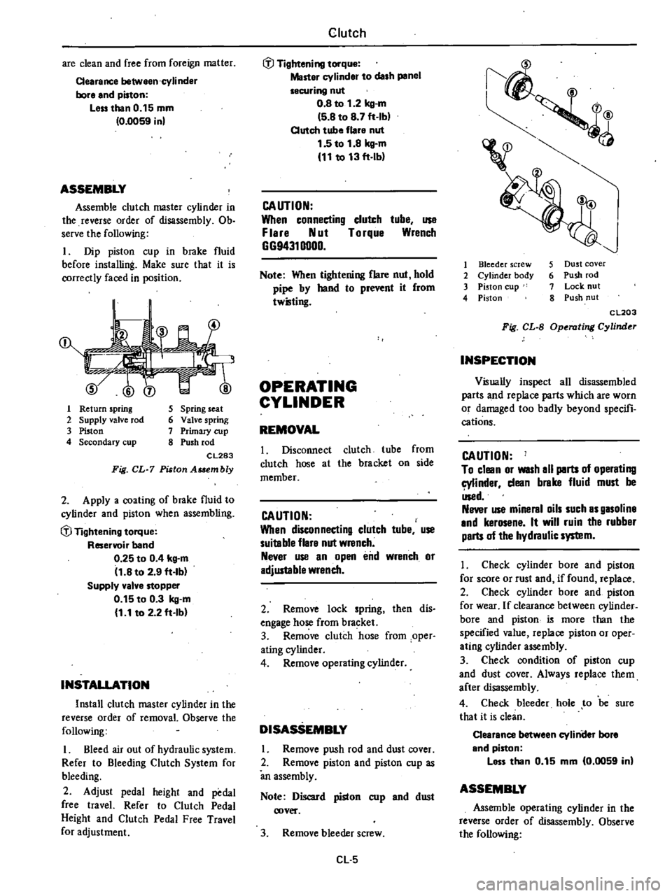
1
Return
spring
2
Supply
valve
rod
3
Piston
4
Secondary
cup
5
Spring
seat
6
Valve
spring
7
Primary
cup
8
Push
rod
CL283
Fig
CL
7
Piston
Asaembly
2
Apply
a
coating
of
brake
fluid
to
cylinder
and
piston
when
assembling
if
Tightening
torque
Reservoir
band
0
25
to
0
4
kg
m
11
8
to
2
9
ft
lb
Supply
valve
stopper
0
15
to
0
3
kg
m
1
1
to
2
2
ft
Ib
INSTALLATION
Install
clutch
master
cylinder
in
the
reverse
order
of
removal
Observe
the
following
I
Bleed
air
out
of
hydraulic
system
Refer
to
Bleeding
Clutch
System
for
bleeding
2
Adjust
pedal
height
and
pedal
free
travel
Refer
to
Clutch
Pedal
Height
and
Clutch
Pedal
Free
Travel
for
adjustment
Clutch
if
Tightening
torque
Master
cylinder
to
dash
panel
securing
nut
0
8
to
1
2
kg
m
5
8
to
8
7
ft
Ib
Clutch
tube
flare
nut
1
5
to
1
8
kg
m
11
to
13
ft
lb
CAUTION
When
connecting
clutch
tube
use
F
lere
Nut
Torque
Wrench
GG94310000
Note
When
tightening
flare
nut
hold
pipe
by
hand
to
r
it
from
twilling
OPERATING
CYLINDER
REMOVAL
I
Disconnect
clutch
tube
from
clutch
hose
at
the
bracket
on
side
member
CAUTION
When
disconnecting
clutch
tube
use
suitable
flare
nut
wrench
Never
use
an
open
end
wrench
or
adjustable
wrench
2
Remove
lock
spring
then
dis
engage
hose
from
bracket
3
Remove
clutch
hose
from
oper
ating
cylinder
4
Remove
operating
cylinder
DISASSEMBLY
Remove
push
rod
and
dust
cover
2
Remove
piston
and
piston
cup
as
an
assembly
Note
Discard
piston
cup
and
dust
cover
3
Remove
bleeder
screw
Cl
5
1
4
v
I
Bleeder
screw
2
Cylinder
body
3
Piston
cup
4
Piston
5
Dust
cover
6
Push
rod
7
Lock
nut
8
Push
nut
CL203
Fig
CL
B
Operating
Cylinder
INSPECTION
Visually
inspect
all
disassembled
parts
and
replace
parts
which
are
worn
or
damaged
too
badly
beyond
specifi
cations
CAUTION
To
clean
or
WISh
all
parts
of
operating
cylinder
dean
brake
fluid
must
be
Used
Never
use
mineral
oils
such
as
gasoline
and
kerosene
It
will
ruin
the
rubber
parts
of
the
hydraulic
system
I
Check
cylinder
bore
and
piston
for
score
or
rust
and
if
found
replace
2
Check
cylinder
bore
and
piston
for
wear
If
clearance
between
cylinder
bore
and
piston
i5
more
than
the
specified
value
replace
piston
or
oper
ating
cylinder
assembly
3
Check
condition
of
piston
cup
and
dust
cover
Always
replace
them
after
disassembly
4
Check
bleeder
hole
to
be
sure
that
it
is
clean
Clearance
between
cyliniler
bore
and
piston
less
than
0
15
mm
0
0059
in
ASSEMBLY
Assemble
operating
cylinder
in
the
reverse
order
of
disassembly
Observe
the
following
Page 212 of 548

Clutch
SERVICE
DATA
AND
SPECIFICATIONS
ENERALSPECIFICATIONS
Clutch
control
system
Type
of
clutch
control
Clutch
master
cylinder
Diameter
Clutch
operating
cylinder
Type
Diameter
Clutch
disc
Type
Facing
size
Outer
dia
x
Inner
dia
x
Thickness
Thicmess
of
disc
assembly
Free
Installed
Number
of
torsion
springs
Clutch
cover
Type
FuU
load
Hydraulic
mill
in
15
88
mm
in
Adjustable
1746
180CBL
mrn
in
180
x
125
x
3
5
7
09
x
4
92
x
0
138
mm
in
mm
in
8
5
to
9
2
0
335
to
0
362
7
6
to
8
0
0
299
to
0
315
6
kg
Ob
CI80S
335
to
385
739
to
849
INSPECTION
AND
ADJUSTMENT
Clutch
pedal
Pedal
height
H
Pedal
free
play
A
Withdiawallever
play
B
Pedalfree
travel
C
Clutch
master
cylinder
Maximum
clearance
between
cylinder
bore
and
piston
Clutch
operating
cylinder
Maximum
clearance
belween
cylinder
bore
and
piston
Clutch
disc
Wear
liinit
of
facing
Depth
of
rivet
head
below
facing
surface
Runoullimit
Distance
of
runout
checking
point
from
the
hub
center
Maximum
backlash
of
spline
at
outer
edge
of
disc
mm
in
mm
in
mm
in
mm
in
143
to
149
5
63
to
5
87
1
to
5
0
04
to
0
20
1
0
to
2
0
0
039
to
0
079
16
to
33
0
63
to
1
30
mm
in
Less
than
0
15
0
0059
mm
in
Less
than
0
15
0
0059
mm
in
mm
in
0
3
0
012
0
5
0
020
mm
in
85
3
35
mm
in
0
4
0
016
CLIO
Page 214 of 548

Condition
Clutch
slips
Clutch
drags
Clutch
TROUBLE
DIAGNOSES
AND
CORRECTIONS
Probable
cause
and
testing
Corrective
action
Slipping
of
clutch
may
be
noticeable
when
any
of
the
following
symptoms
is
encountered
during
operation
I
Car
will
not
respond
to
erigine
speed
during
acceleration
2
Insufficient
car
speed
3
Lack
of
power
during
uphill
driving
Some
of
the
above
conditions
may
also
be
attributable
to
engine
problem
First
determine
whether
engine
or
clutch
is
causing
the
problem
If
slipping
clutch
is
left
unheeded
wear
and
or
overheating
will
occur
on
clutch
facing
to
such
an
extent
that
it
is
no
longer
serviceable
TO
TEST
FOR
SLIPPING
CLurCH
proceed
as
follows
During
upgrade
havelling
run
engine
at
about
40
to
50
km
h
25
to
31
MPH
with
gear
shift
lever
in
3rd
speed
position
shift
into
highest
gear
and
t
the
same
time
rev
up
engine
If
clutch
is
slipping
car
willnot
readily
respond
to
depression
of
accelerator
pedal
Clutch
facing
warn
excessively
Oil
or
grease
on
clutch
facing
Warped
clutch
cover
or
pressure
plate
Replace
Replace
Repair
or
replace
Dragging
clu
tch
is
particularly
noticeable
when
shifting
gears
especially
into
low
gear
TO
TEST
FOR
DRAGGING
CLurCH
proceed
as
follows
I
Start
engine
Disengage
clutch
Shift
into
reverse
gear
and
then
into
Neutral
Gradually
increase
engine
speed
and
again
shift
into
reverse
gear
If
clutch
is
dragging
gear
grating
is
heard
when
shifting
gears
from
Neutral
into
Reverse
2
Stop
engine
and
shift
gears
Conduct
this
test
at
each
gear
position
3
In
step
2
gears
are
shifted
smoothly
except
1st
speed
position
at
idling
a
If
dragging
is
encountered
at
the
end
of
shifting
check
condition
of
synchro
mechanism
in
transmission
b
If
dragging
is
encountered
at
the
beginning
of
shifting
proceed
to
step
4
below
4
Push
change
lever
toward
Reverse
ide
depress
pedal
to
check
for
free
travel
of
pedal
a
If
pedal
can
be
depressed
further
check
clutch
for
condition
b
If
pedal
cannot
be
depressed
further
proceed
to
step
5
below
5
Check
clutch
control
pedal
height
pedal
free
play
free
travel
withdrawal
lever
play
etc
If
any
abnormal
condition
does
not
exist
and
if
pedal
cannot
be
depressed
further
check
clutch
for
condition
Clutch
disc
runout
or
warped
Wear
or
rust
on
hub
splines
in
clutch
disc
Diaphragm
spring
toe
height
out
of
adjustment
or
toe
tip
worn
Worn
or
improperly
installed
parts
Replace
Clean
and
lubricate
with
grease
or
replace
Adjust
or
replace
Repair
or
replace
CL12
Page 307 of 548

DATSUN
2JO
Model
83
J
0
Series
SECTIONPD
PROPELLER
SHAFT
DIFFERENTIAL
CARRIER
CONTENTS
PROPELLER
SHAFT
INSPECTION
GENERAL
INSPECTION
PROPEllER
SHAFT
VIBRATION
REMOVAL
AND
INSTAllATION
REMOVAL
INSTAllATION
DIFFERENTIAL
CARRIER
REMOVAL
PRE
DISASSEMBl
Y
INSPECTION
DISASSEMBLY
FINAL
DRIVE
ASSEMBLY
DIFFERENTIAL
CASE
INSPECTION
ASSEMBl
Y
AND
ADJUSTMENT
PRECAUTIONS
IN
REASSEMBLY
ASSEMBLY
OF
DIFFERENTIAL
CASE
ADJUSTMENT
OF
DRIVE
PINION
HEIGHT
ADJUSTMENT
OF
DRIVE
PINION
PRELOAD
PD
2
PD
2
PD
2
PD
2
PD
2
PD
2
PD
2
PD
3
PD
3
PD
3
PD
4
PD
4
PD
4
PD
4
PD
5
PD
5
PD
5
PD
6
PD
6
AQJUSTMENT
OF
SIDE
BEARING
SHIMS
INSTAllATION
REPLACEMENT
OF
FRONT
Oil
SEAL
SERVICE
DATA
AND
SPECIFICATIONS
PROPEllER
SHAFT
GENERAL
SPECIFICATIONS
SERVICE
DATA
TIGHTENING
TORQUE
DIFFERENTIAL
CARRIER
GENERAL
SPECIFICATIONS
SERVICE
DATA
TIGHTENING
TORQUE
TROUBLE
DIAGNOSES
AND
CORRECTIONS
PROPEllER
SHAFT
DIFFERENTIAL
CARRIER
SPECIAL
SERVICE
TOOLS
PD
7
PD
9
PD
9
PD
lO
PD
lO
PD
lO
PD
lO
PD
lO
PD
l0
PD
lO
PD
ll
PD
ll
PD
12
PD
12
PD
13
PD
15
Page 312 of 548

ADJUSTMENT
OF
DRIVE
PINION
HEIGHT
Adjust
the
pinion
height
with
wash
er
provided
between
rear
bearing
inner
race
and
the
back
of
piliion
gear
J
Press
fit
front
and
rear
bearing
outer
races
into
gear
carrier
using
Drive
Pinion
Outer
Race
Drift
STJ070
I
000
and
Bar
ST30611000
2
Fit
rear
bearing
on
gear
carrier
and
install
Dwnmy
Shaft
on
rear
bear
ing
and
place
Height
Gauge
on
gear
carrier
STJII21000
Height
gauge
KV38
103500
Height
gauge
spacer
ST3
II
22000
Dummy
shaft
KV3gl03600
Dummy
shaft
spacer
ST3112tOOO
PD461
Fig
PD
14
AqjUlting
Pinion
Height
3
Measure
the
clearance
N
be
tween
the
tip
end
of
height
gauge
and
the
end
surface
of
dummy
shaft
using
a
thickness
gauge
P0322
Fig
PD
15
Meo
uring
Clearance
4
The
proper
thickness
of
pinion
height
adjusting
washers
can
be
obtain
ed
from
the
following
formula
Propeller
Shaft
Differential
Carrier
T
W
N
HxO
01
OJ8
Where
T
Required
thickness
of
pinion
heightedjusting
w
shers
W
Thickness
of
temporarily
insert
ed
washer
mm
Be
sure
to
use
washer
of
2
74
0
1079
or
2
77
0
1091
or
2
80
0
1102
mm
in
thick
ness
N
Measured
clearance
between
height
gauge
and
dummy
shaft
face
mm
H
Figure
marked
on
the
drive
pinion
head
Note
e
Figure
H
is
e
dimensional
variation
in
units
of
1
100
mm
egainst
stand
ard
measurement
b
If
value
signifying
H
is
not
given
regard
it
as
zero
and
compute
Head
number
Hl
P0186
Set
number
Fig
PD
16
Variation
Number
on
Drive
Pinion
Examples
of
calculation
EX
I
W
2
74mmN
0
30mmH
1
T
W
N
H
x
0
01
0
18
2
74
0
30
I
x
0
01
OJ8
3
04
0
19
2
85
The
correct
washer
thickness
is
2
86
mm
EX
2
W
2
77
mm
N
0
21
mm
H
0
T
W
N
HxO
01
OJ8
2
77
0
21
OxO
0I
OJ8
2
98
0
18
2
80
The
correct
washer
thickness
is
2
g0
mm
PD
6
EX
3
W
2
80
mm
N
0
48
mm
H
2
T
W
N
HxO
OI
OJg
2
80
OA8
2
x
0
01
OJ8
3
28
0
20
3
08
The
correct
washer
thickness
is
3
07
mm
Pinion
height
adjusting
washer
Thickness
mm
in
2
74
OJ
079
3
01
0
1185
2
77
OJ09I
3
04
0
1197
2
80
OJ
102
3
07
0
1209
2
83
0
1114
3
10
0
1220
2
86
OJ
126
3J3
0
1232
2
89
0
1138
3
16
0
1244
2
92
OJ
150
3
19
0
1256
2
95
0
1161
3
22
OJ
268
2
98
0
1173
3
25
O
l2g0
5
Fit
detennined
pinion
height
ad
justing
washer
in
drive
pinion
and
press
fit
rear
bearing
inner
race
in
it
using
Drive
Pinion
Bearing
Drift
Bar
STJ0600000
Note
After
assembly
check
to
see
thet
tooth
contact
is
correct
If
Dot
readjust
ADJUSTMENT
OF
DRIVE
PINION
PRELOAD
Adjust
the
preload
of
drive
pinion
with
collapsible
spacer
This
procedure
has
nothing
to
do
with
thickness
of
pinion
height
ad
justing
washer
Note
Collapsible
spacer
oil
seal
and
pinion
nut
cannot
be
reused
I
After
adjusting
pinion
height
lubricate
front
bearing
with
gear
oil
and
place
it
in
gear
carrier
2
Install
a
new
oil
seal
in
gear
carrier
using
Oil
Seal
Fitting
Tool
ST33400001
Lubricate
cavity
between
seal
lips
with
recommended
multi
purpose
grease
when
installing
3
Place
a
new
collapsible
spacer
on
Page 354 of 548
BRAKE
PEDAL
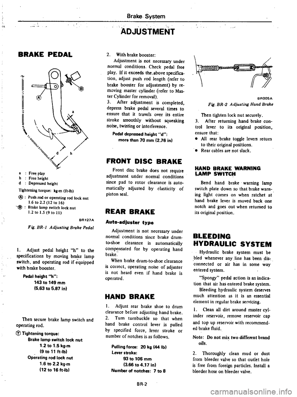
a
a
Fr
play
h
Free
height
d
Depressed
height
Tightening
torque
Icg
m
ft
tb
@
@
Push
rod
or
operating
rod
lock
nut
1
6
to
2
2
12
to
16
Brake
lainp
switch
lock
nut
1
2
to
I
5
9
to
11
BR121A
Fig
BR
1
Adjusting
Broke
Pedal
I
Adjust
pedal
height
h
to
the
specifications
by
moving
brake
lamp
switch
and
operating
rod
if
equipped
with
brake
booster
Pedal
height
h
143
to
149
mm
5
63
to
5
87
inl
Then
secure
brake
lamp
switch
and
operating
rod
C
l
Tightening
tOlque
Blake
lamp
witch
lock
nut
1
2
to
1
5
kg
m
9
to
11
ft
lb
Operating
lad
lock
nut
1
6
to
2
2
kg
m
12
to
16
ft
b
Brake
System
ADJUSTMENT
2
With
brake
booster
Adjustment
is
not
necessary
under
normal
conditions
Check
pedal
free
play
If
it
exceeds
the
above
specifica
tion
adjust
push
rod
length
refer
to
brake
booster
for
adjustment
by
re
moving
master
cylinder
rerer
to
Mas
ter
Cylinder
for
removal
3
After
adjustment
is
completed
depress
brake
pedal
several
times
to
ensure
that
it
travels
over
its
entire
stroke
smoothly
without
squeaking
noise
twisting
or
interference
Pedal
depr
d
Might
d
more
than
70
mm
2
76
in
FRONT
DISC
BRAKE
Front
disc
brake
does
not
require
adjustment
under
normal
conditions
since
pad
to
rotor
clearance
is
auto
malically
adjusted
by
elasticity
of
piston
seal
REAR
BRAKE
Auto
edJuster
type
Adjustment
is
not
necessary
under
normal
conditions
since
brake
drum
t
shoe
clearance
is
automatically
compensated
for
by
operating
hand
brake
Wlien
brake
drum
to
shoe
clearance
is
correct
operating
noise
of
adjuster
is
not
heard
even
if
hand
brake
is
operated
HAND
BRAKE
I
Adjust
rear
brake
shoe
to
drum
clearance
before
adjusting
hand
brake
2
Turn
turnbuckle
so
that
when
hand
brake
control
lever
is
pulled
by
specified
force
lever
stroke
or
number
of
notches
is
as
follows
Pulling
fOil
20
kg
44
Ib
lever
stroke
93
to
106
mm
3
66
to
4
17
in
Numbel
of
notches
7
to
8
BR
2
f
BAQ05A
Fig
BR
2
Adjusting
Hand
Brake
Then
tighten
lock
nut
securely
3
After
returning
hand
brake
con
trol
lever
to
its
original
position
ensure
that
e
All
rear
brake
toggle
levers
return
to
their
original
positions
Rear
cables
are
not
slack
HAND
BRAKE
WARNING
LAMP
SWITCH
Bend
hand
brake
warning
lamp
switch
plate
down
so
that
brake
warn
ing
light
comes
on
when
ratchet
at
hand
brake
lever
is
moved
back
one
notch
and
goes
out
when
returned
to
its
original
position
BLEEDING
HYDRAULIC
SYSTEM
Hydraulic
brake
system
must
be
bled
whenever
any
line
has
been
dis
connected
or
air
has
in
some
way
entered
system
Spongy
pedal
action
is
an
indica
tion
that
air
has
entered
brake
system
Bleeding
hydraulic
system
deserves
much
attention
as
it
is
an
essential
element
in
regular
brake
servicing
Clean
all
dirt
around
master
cyl
inder
reservoir
remove
reservoir
cap
and
top
up
reservoir
with
recommend
edbrake
fluid
Note
Do
not
mix
two
different
brand
oils
2
Thoroughly
clean
mud
or
dust
from
bleeder
valve
so
that
outlet
hole
is
free
from
foreign
particles
Install
a
bleeder
hose
on
bleeder
valve