instrument cluster DATSUN 210 1979 Service Manual
[x] Cancel search | Manufacturer: DATSUN, Model Year: 1979, Model line: 210, Model: DATSUN 210 1979Pages: 548, PDF Size: 28.66 MB
Page 76 of 548
Not
Pump
rotors
and
body
are
not
serv
iced
separatdy
If
pump
rotors
or
body
are
damaged
or
worn
replace
ment
of
the
entire
oil
pump
assembly
isnecessary
OIL
PRESSURE
REGULATOR
VALVE
The
oil
pressure
regulator
valve
is
not
adjustable
At
the
released
posi
tion
the
valve
permits
the
oil
to
by
pass
through
the
passage
in
the
pump
cover
to
the
inlet
side
of
the
pump
Check
regulator
valve
spring
to
ensure
that
spring
tension
is
correct
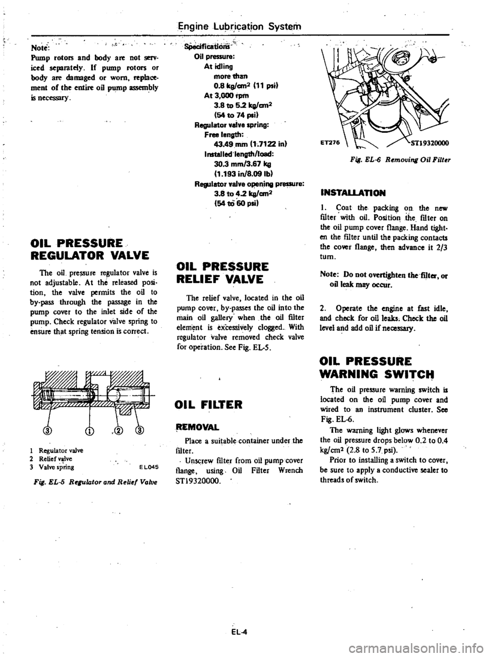
no
1
Regulator
valve
2
Relief
valve
3
Valve
spring
E
L045
Fig
EL
5
Regulator
and
Reli
Vatv
Engine
Lubrication
System
8Peciflcatlons
Oil
pressure
At
idling
more
than
O
Blrg
an2
11
psi
At
3
000
rpm
3
B
to
5
2lrg
an2
54
to
74
psi
Regulator
ai
spring
Free
length
43
49
rom
1
7122
in
InstoJlod
l
ngth
load
30
3
mm
3
67
kg
1
193
inJB
09lbl
Regulator
val
o
ning
pressur
3
8
to
4
2
lrg
an2
54
1060
psi
OIL
PRESSURE
RELIEF
VALVE
The
relief
valve
located
in
the
oil
pump
cover
by
passes
the
oil
into
the
main
oil
gallery
when
the
oil
filter
elem
nt
is
exCessively
clogged
With
regula
tor
valve
removed
check
valve
for
operation
See
Fig
EL
5
OIL
FILTER
tEMOVAL
Place
a
suitable
container
under
the
f1lter
Unscrew
f1lter
from
oil
pump
cover
flange
using
Oil
Filter
Wrench
STl9320000
EL
4
Fig
EL
6
Removing
Oil
Filter
INSTALLAnON
I
Coat
the
packing
on
the
new
f1lter
with
oil
Position
the
f1lter
on
the
oil
pump
cover
flange
Hand
tight
en
the
f11ter
until
the
packing
contacts
the
cover
flange
then
advance
it
2
3
tum
Note
Do
not
overtighten
the
fiIter
or
oil
leak
may
occur
2
Operate
the
engine
at
fast
idle
and
check
for
oil
leaks
Check
the
oil
level
and
add
oil
if
necessary
OIL
PRESSURE
WARNING
SWITCIt
The
oil
pressure
warning
switch
is
located
on
the
oil
pump
cover
and
wired
to
an
instrument
cluster
See
Fig
EL
6
The
warning
light
glows
whenever
the
oil
pressure
drops
below
0
2
to
0
4
kg
cm1
2
8
to
5
7
psi
Prior
to
installing
a
switch
to
cover
I
be
sure
to
apply
a
conductive
sealer
to
threads
of
switch
Page 440 of 548
INSTRUMENT
PANEL
Body
INTERIOR
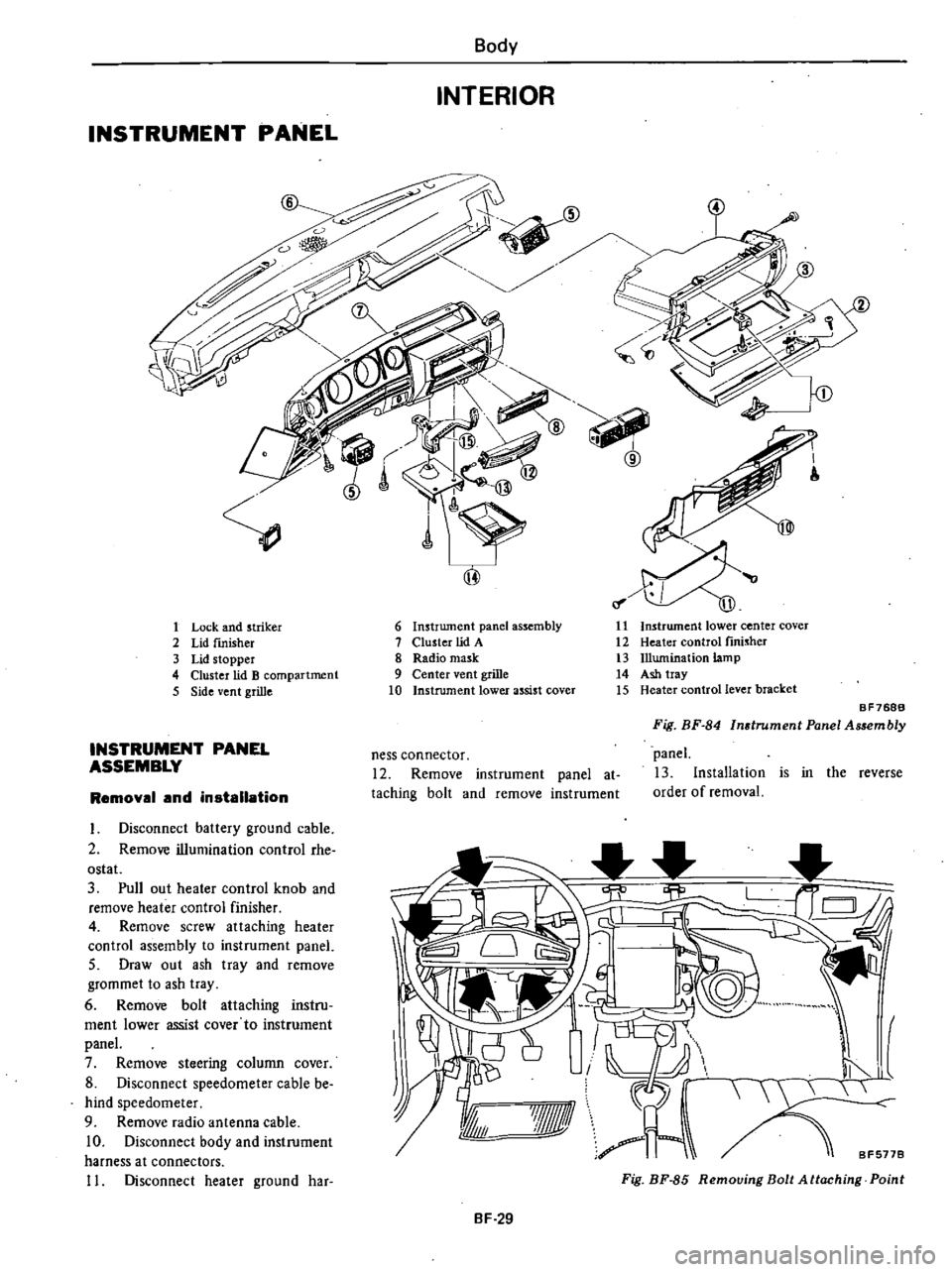
1
Lock
and
striker
2
Lid
fInisher
3
Lid
stopper
4
Cluster
lid
B
compartment
5
Side
vent
grille
INSTRUMENT
PANEL
ASSEMBLY
Removal
and
installation
I
Disconnect
battery
ground
cable
2
Remove
illumination
control
rhe
ostat
3
Pull
out
heater
control
knob
and
remove
heater
control
finisher
4
Remove
screw
attaching
heater
control
assembly
to
instrument
panel
5
Draw
out
ash
tray
and
remove
grommet
to
ash
tray
6
Remove
bolt
attaching
instru
ment
lower
assist
cover
to
instrument
panel
7
Remove
steering
column
cover
8
Disconnect
speedometer
cable
be
hind
speedometer
9
Remove
radio
antenna
cable
10
Disconnect
body
and
instrument
harness
at
connectors
11
Disconnect
heater
ground
har
6
Instrument
panel
assembly
7
Cluster
lid
A
8
Radio
mask
9
Center
vent
grille
10
Instrument
lower
assist
cover
11
Instrument
lower
center
cover
12
Heater
control
fInisher
13
Illumination
lamp
14
Ash
tray
15
Heater
control
lever
bracket
ness
connector
12
Remove
instrument
panel
at
taching
bolt
and
remove
instrument
BF768B
Fig
BF
84
Instrument
Panel
Assembly
panel
13
Installation
is
in
the
reverse
order
of
removal
I
I
I
8F5778
7Jf1ll
A
Fig
BF
85
Removing
Bolt
Attaching
Point
BF
29
Page 441 of 548
CLUSTER
I
IDA
Removal
and
installation
I
Disconnect
batterv
ground
cable
2
Remove
steering
column
cover
3
Remove
illumination
control
rhe
ostat
4
Pull
out
heater
control
knob
and
remove
heater
c
ntrol
finisher
5
Remove
screw
attaching
heater
control
assembly
to
cluster
lid
A
nQ
lQ
Ii
tl
rffmfLu
O
r
BF783B
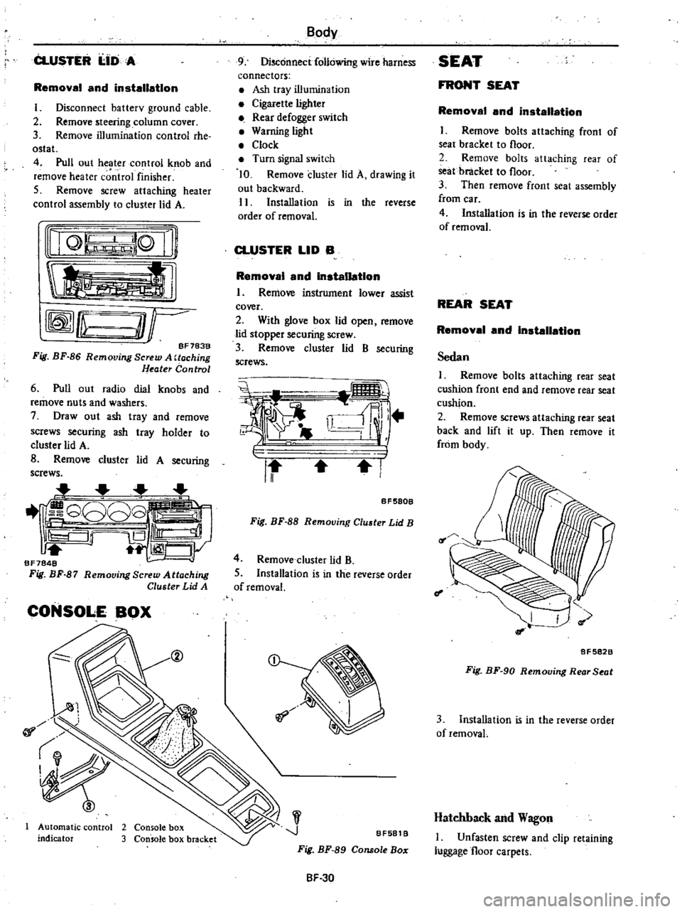
Fig
BF
86
Removing
Screw
A
Uoching
Heater
Control
6
Pull
out
radio
dial
knobs
and
remove
nuts
and
washers
7
Draw
out
ash
tray
and
remove
screws
securing
ash
tray
holder
to
cluster
lid
A
B
Remove
cluster
lid
A
securing
screws
1
G808
iS
Ill
1
CJy
BF7848
Fig
BF
87
Remooing
Screw
Attaching
Cluster
Lid
A
CONSOLE
BOX
@
01
Automatic
control
2
Console
box
indicator
3
Console
box
bracket
Body
9
Disconnect
following
wire
harness
connectors
Ash
tray
illumination
Cigarette
lighter
Rear
defogger
switch
Warning
light
Clock
Turn
signal
switch
10
Remove
cluster
lid
A
drawing
it
out
backward
11
Installation
is
in
the
reverse
order
of
removal
CLUSTER
LID
B
Removal
and
Installation
I
Remove
instrument
lower
assist
cover
2
With
glove
box
lid
open
remove
lid
stopper
securing
screw
3
Remove
cluster
lid
B
securing
screws
i
i
ll
r
II
I
BF580B
Fig
BF
88
Removing
Cluster
Lid
B
4
Remove
cluster
lid
B
5
Installation
is
in
the
reverse
order
of
removal
J
BF581
B
Fig
BF
89
Console
Bo
SF
30
SEAT
FRONT
SEAT
Removal
and
installation
I
Remove
bolts
attaching
front
of
seat
bracket
to
floor
2
Remove
bolts
attaching
rear
of
seat
bracket
to
floor
3
Then
remove
front
seat
assembly
from
car
4
Installation
is
in
the
reverse
order
of
removal
REAR
SEAT
Removal
and
Installation
Sedan
I
Remove
bolts
attaching
rear
seat
cushion
front
end
and
remove
rear
seat
cushion
2
Remove
screws
attaching
rear
seat
back
and
lift
it
up
Then
remove
it
from
body
f
I
8F5828
Fig
BF
90
Removing
Rear
Seat
3
Installation
is
in
the
reverse
order
of
removaL
Hatchback
and
Wagon
I
Unfasten
screw
and
clip
retaining
luggage
floor
carpets
Page 458 of 548
Body
Electrical
System
INSPECTION
4
Installation
is
in
the
reverse
order
of
removal
Test
continuity
through
door
switch
with
a
test
lamp
or
ohmmeter
When
plunger
is
pressed
into
switch
assembly
door
switch
contacts
are
open
Contacts
are
closed
when
plung
er
is
projected
METERS
AND
GAUGES
3
Remove
steering
column
cover
4
Remove
cluster
lid
A
referring
to
Instrument
Panel
Section
BF
for
reqlOval
and
installation
5
Remove
retaining
screws
6
Disconnect
speedometer
cable
by
pushing
and
turning
connector
cap
counterclockwise
7
Disconnect
lead
wire
terminals
for
multi
pole
connector
and
tachome
ter
if
so
equipped
8
Install
combination
meter
in
the
reverse
order
of
removal
CAUTION
Before
starting
to
work
on
any
part
of
electrical
sYstem
disconnect
battery
ground
cable
COMBINATION
METER
Note
Be
careful
not
to
damage
print
ed
circuit
I
Disconnect
battery
ground
cable
2
Remove
steering
wheel
CD
Cl
B
i
lJ
Q
@
8
0
I
0
w
@
@
I
Q
a
d
Q
Q
J
Q
2
Cl
0
a
w
Q
3
j
J
Z
t
0
J
W
C
I
0
9
J
CI
C
CI
J
0
I
Q
a
Cl
w
z
J
w
Z
a
c
o
0
3
S2
J1
J2
a
a
l
gO
C
4
l
w
I
EO
l
c
zO
zO
1
Cl
CjU
z
3
Q
Q
w
c
ffi
ffi
to
J
C
U
en
a
C
a
w
i
r
@
p
g10
l
0
U
lJ
v
v
zO
8
7
12
11
10
Q
o
I
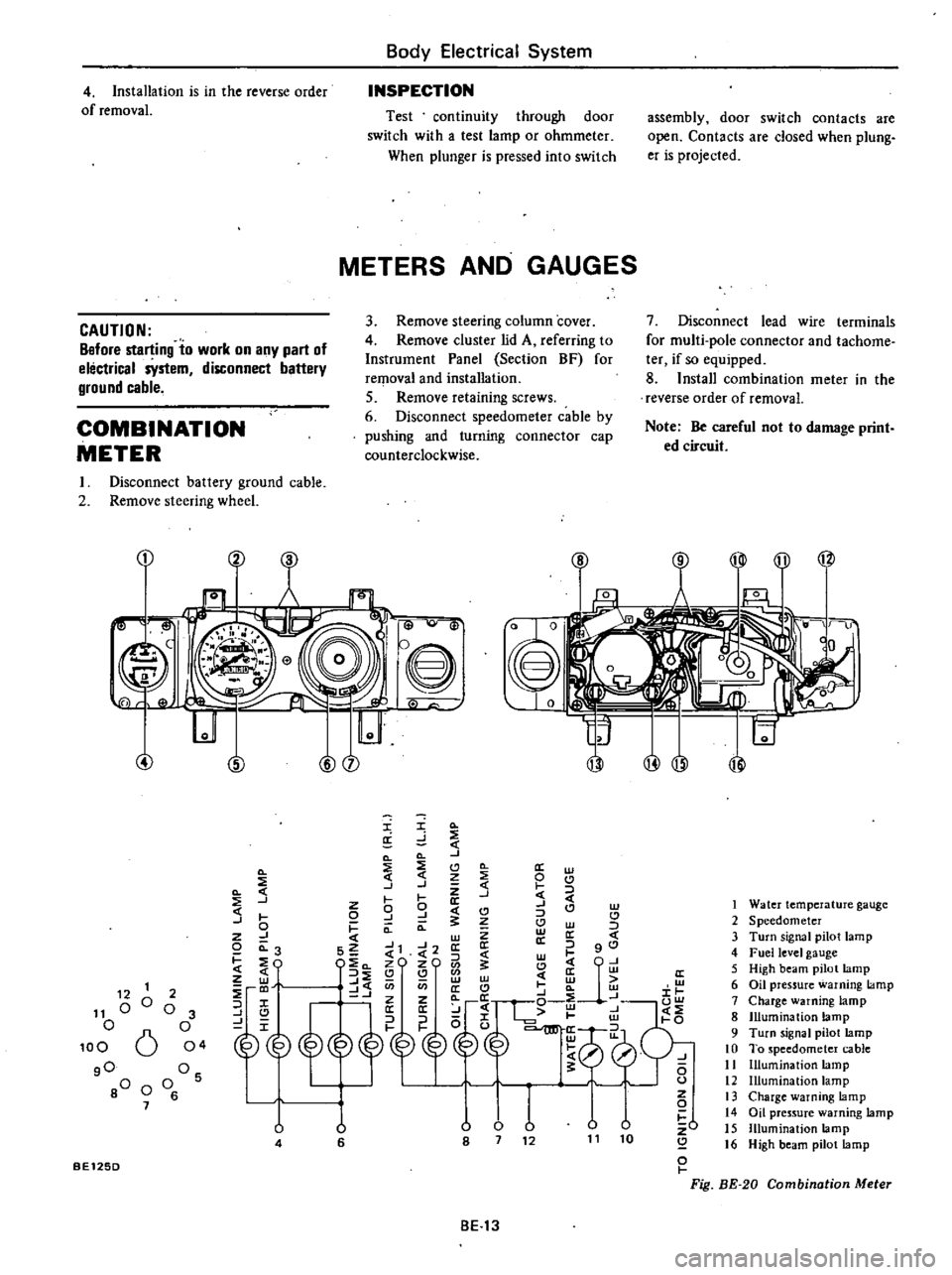
Fig
BE
20
Combination
Meter
1
Water
temperature
gauge
2
Speedometer
3
Turn
signal
pilot
lamp
4
Fuel
level
gauge
5
High
beam
pilot
lamp
6
Oil
pressure
warning
lamp
7
Charge
warning
lamp
8
Illumination
lamp
9
Turn
signal
pilot
lamp
10
To
speedometer
cable
11
Illumination
lamp
12
Illumination
lamp
13
Charge
warning
lamp
14
Oil
pressure
warning
lamp
15
Illumination
lamp
16
High
beam
pilot
lamp
12
1
11
00
o
100
6
gO
80
0
7
2
o
3
o
04
Os
o
6
U
4
u
6
BE125D
BE13
Page 460 of 548
CHARGE
WARNING
SYSTEM
Refer
to
Section
EE
BRAKE
WARNING
SYSTEM
REPLACEMENT
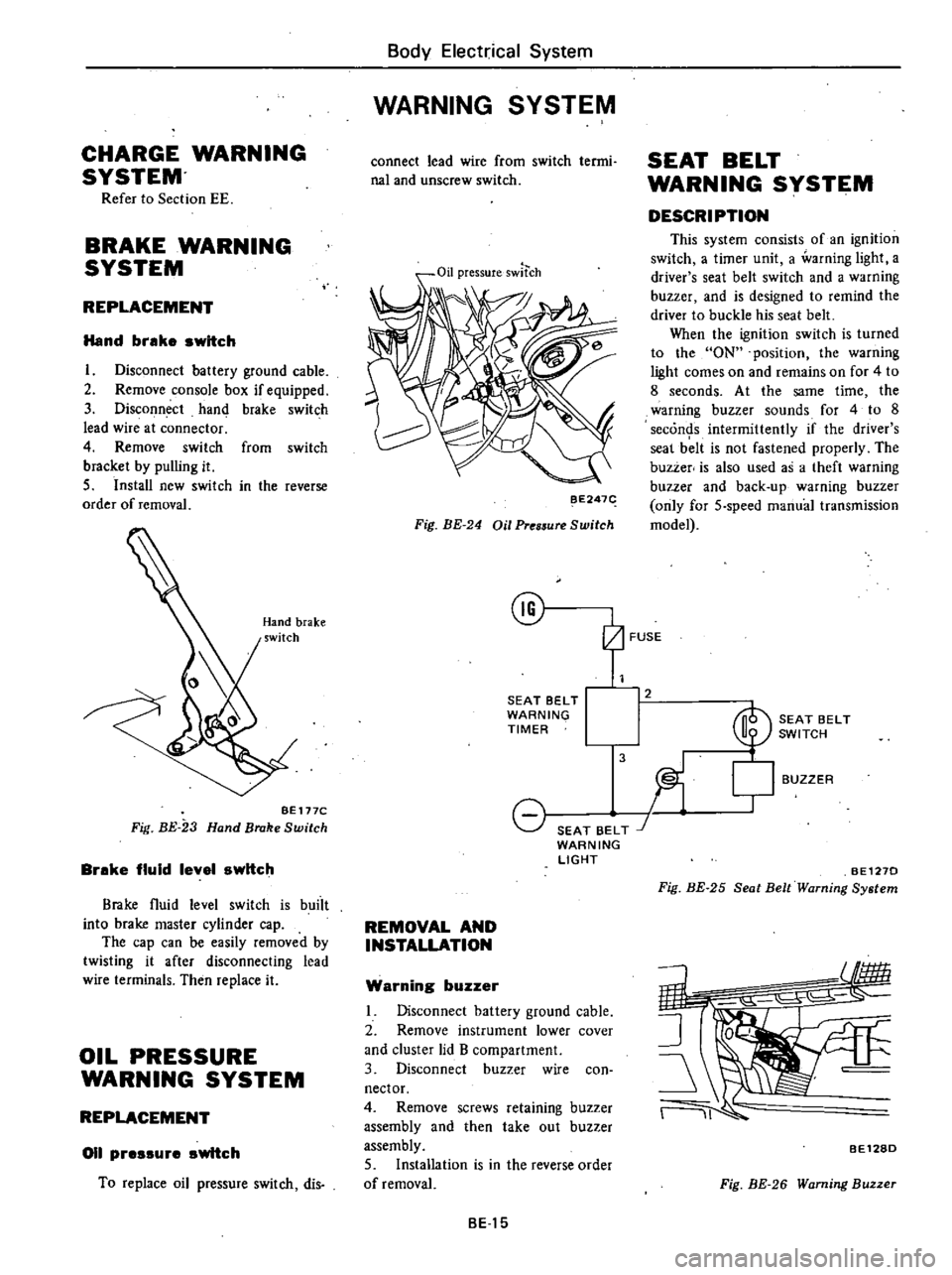
Hand
brake
switch
I
Disconnect
battery
ground
cable
2
Remove
console
box
if
equipped
3
Disconnect
hand
brake
switch
lead
wire
at
connector
4
Remove
switch
from
switch
bracket
by
pulling
it
5
Install
new
switch
in
the
reverse
order
of
removal
BE
177C
Fig
BE
23
Hand
Brake
Switch
Brake
fluid
level
switch
Brake
fluid
level
switch
is
buiit
into
brake
master
cylinder
cap
The
cap
can
be
easily
removed
by
twisting
it
after
disconnecting
lead
wire
terminals
Then
replace
it
OIL
PRESSURE
WARNING
SYSTEM
REPLACEMENT
011
pressure
switch
To
replace
oil
pressure
switch
dis
Body
Electrical
System
WARNING
SYSTEM
connect
lead
wire
from
switch
termi
nal
and
unscrew
switch
Oil
pressureswltch
BE247
Fig
BE
24
Oil
Pres5ure
Switch
@
SEAT
BELT
WARNING
TIMER
8
SEAT
BELT
J
WARNING
LIGHT
REMOVAL
AND
INSTALLATION
Warning
buzzer
Disconnect
battery
ground
cable
2
Remove
instrument
lower
cover
and
cluster
lid
B
compartment
3
Disconnect
buzzer
wire
con
nector
4
Remove
screws
retaining
buzzer
assembly
and
then
take
out
buzzer
assembly
5
Installation
is
in
the
reverse
order
of
removal
BE15
SEAT
BELT
WARNING
SYSTEM
DESCRIPTION
This
system
consists
of
an
ignition
switch
a
timer
unit
a
warning
light
a
driver
s
seat
belt
switch
and
a
warning
buzzer
and
is
designed
to
remind
the
driver
to
buckle
his
seat
belt
When
the
ignition
switch
is
turned
to
the
ON
position
the
warning
light
comes
on
and
remains
on
for
4
to
8
seconds
At
the
same
time
the
warning
buzzer
sounds
for
4
to
8
seconds
intermittently
if
the
driver
s
seal
b
lt
is
not
fastened
properly
The
buzzer
is
also
used
as
a
theft
warning
buzzer
and
back
up
warning
buzzer
only
for
5
speed
manual
transmission
model
2
3
BUZZER
SEAT
BELT
SWITCH
l
BE1270
Fig
BE
25
Seat
Belt
Warning
System
11
BE128D
Fig
BE
26
Warning
Buzzer
Page 471 of 548
REMOVAL
AND
INSTALLATION
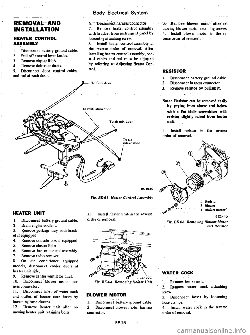
HEATER
CONTROL
SEMBLY
I
Disconnect
battery
ground
cable
2
Pull
off
control
lever
knobs
3
Remove
cllJs
r
lid
A
4
Remove
defroster
ducts
5
Disconnect
door
control
cables
and
rod
at
each
door
Body
Electrical
System
6
Disconnectharness
tonnec1or
7
Remove
heater
control
assembly
with
bracket
from
instrument
panel
by
loosening
attaching
screw
8
Install
heater
control
assembly
in
the
reverse
order
of
removal
After
installing
heater
oontrol
assembly
oon
trol
cables
and
rod
must
be
adjusted
by
referring
to
Adjusting
Heater
Con
trol
HEATER
UNIT
I
Disconnect
battery
ground
cable
2
Drain
engine
coolant
3
Remove
package
tray
with
brack
et
if
equipped
4
Remove
console
box
if
equipped
5
Remove
cluster
lid
A
6
Remove
heater
control
assembly
7
Remove
radio
receiver
8
On
air
conditioner
equipped
models
disconnect
cooler
ducts
at
heater
unit
side
9
Remove
center
ventilator
duct
10
Disconnect
blower
motor
har
ness
connector
II
Disconnect
inlet
of
wat
r
cock
and
outlet
of
heater
core
hoses
by
loosening
hose
clamps
12
Remove
heater
unit
after
re
moving
heater
unit
retaining
bolts
To
air
intake
door
BE19
C
Fig
BE
63
Heater
Control
Assembly
13
Install
heater
unit
in
the
reverse
order
or
removal
rf
o
t
a
1
BE190C
Fig
BE
64
Removing
Heater
Unit
BLOWER
MOTOR
I
Disconnect
battery
ground
cable
2
Disconnect
blower
motor
harness
connector
BE
26
3
Remove
blower
moto
after
rti
moving
blower
motor
retaining
screws
4
Install
blower
motor
in
the
re
verse
order
of
removal
RESISTOR
I
Disconnect
battery
ground
cable
2
Disconnect
harness
connector
3
Remove
resistor
by
pulling
it
Note
Resistor
can
be
removed
iIy
by
prying
from
above
and
below
with
a
fbt
blade
screwdriver
with
resmor
slightly
raised
from
heater
unit
4
Install
resistor
in
the
reverse
order
of
removal
1
Remtor
2
Blower
3
BlOWer
motor
BE244D
Fig
BE
65
Removing
Blower
Motor
and
Resistor
WATER
COCK
I
Remove
heater
unit
2
Remove
water
cock
attaching
screw
3
Disconnect
hoses
by
loosening
hose
clamps
4
Install
water
cock
in
the
reverse
order
of
removal