fog light DATSUN 210 1979 Service Manual
[x] Cancel search | Manufacturer: DATSUN, Model Year: 1979, Model line: 210, Model: DATSUN 210 1979Pages: 548, PDF Size: 28.66 MB
Page 441 of 548
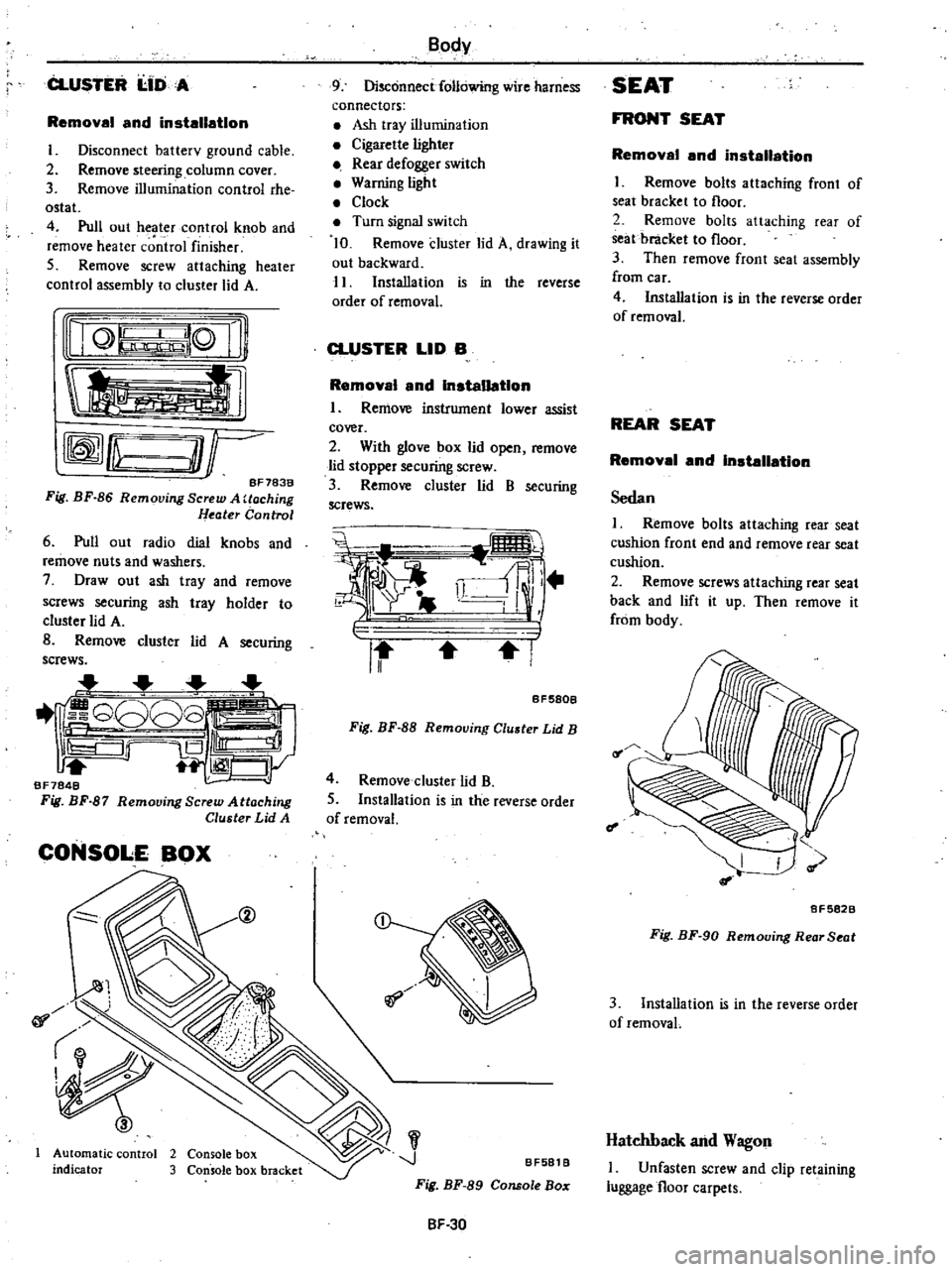
CLUSTER
I
IDA
Removal
and
installation
I
Disconnect
batterv
ground
cable
2
Remove
steering
column
cover
3
Remove
illumination
control
rhe
ostat
4
Pull
out
heater
control
knob
and
remove
heater
c
ntrol
finisher
5
Remove
screw
attaching
heater
control
assembly
to
cluster
lid
A
nQ
lQ
Ii
tl
rffmfLu
O
r
BF783B
Fig
BF
86
Removing
Screw
A
Uoching
Heater
Control
6
Pull
out
radio
dial
knobs
and
remove
nuts
and
washers
7
Draw
out
ash
tray
and
remove
screws
securing
ash
tray
holder
to
cluster
lid
A
B
Remove
cluster
lid
A
securing
screws
1
G808
iS
Ill
1
CJy
BF7848
Fig
BF
87
Remooing
Screw
Attaching
Cluster
Lid
A
CONSOLE
BOX
@
01
Automatic
control
2
Console
box
indicator
3
Console
box
bracket
Body
9
Disconnect
following
wire
harness
connectors
Ash
tray
illumination
Cigarette
lighter
Rear
defogger
switch
Warning
light
Clock
Turn
signal
switch
10
Remove
cluster
lid
A
drawing
it
out
backward
11
Installation
is
in
the
reverse
order
of
removal
CLUSTER
LID
B
Removal
and
Installation
I
Remove
instrument
lower
assist
cover
2
With
glove
box
lid
open
remove
lid
stopper
securing
screw
3
Remove
cluster
lid
B
securing
screws
i
i
ll
r
II
I
BF580B
Fig
BF
88
Removing
Cluster
Lid
B
4
Remove
cluster
lid
B
5
Installation
is
in
the
reverse
order
of
removal
J
BF581
B
Fig
BF
89
Console
Bo
SF
30
SEAT
FRONT
SEAT
Removal
and
installation
I
Remove
bolts
attaching
front
of
seat
bracket
to
floor
2
Remove
bolts
attaching
rear
of
seat
bracket
to
floor
3
Then
remove
front
seat
assembly
from
car
4
Installation
is
in
the
reverse
order
of
removal
REAR
SEAT
Removal
and
Installation
Sedan
I
Remove
bolts
attaching
rear
seat
cushion
front
end
and
remove
rear
seat
cushion
2
Remove
screws
attaching
rear
seat
back
and
lift
it
up
Then
remove
it
from
body
f
I
8F5828
Fig
BF
90
Removing
Rear
Seat
3
Installation
is
in
the
reverse
order
of
removaL
Hatchback
and
Wagon
I
Unfasten
screw
and
clip
retaining
luggage
floor
carpets
Page 446 of 548
DATSUN
210
Model
8310
Series
SECTIONBE
BODY
ELECTRICAL
SYSTEM
CONTENTS
BODY
ELECTRICAL
WIRING
DESCRIPTION
FUSE
AND
FUSIBLE
LINK
WIRING
WIRING
HARNESS
LOCATION
OF
ELECTRICAL
UNIT
ELECTRICAL
UNIT
OF
LIGHTING
SYSTEM
BULB
SPECIFICATIONS
REMOVAL
AND
INSTALLATION
For
lamp
IGNITION
SWITCH
COMBINATION
SWITCH
ILLUMINATION
CONTROL
UNIT
AIMING
ADJUSTMENT
ELECTRICAL
UNIT
OF
SIGNAL
SYSTEM
BE
12
TURN
SIGNAL
SWITCH
BE
12
HORN
RELAY
BE
12
HAZARD
SWITCH
BE
12
STOP
LAMP
SWITCH
BE
12
BACK
UP
LAMP
SWITCH
BE
12
DOOR
SWITCH
BE
12
METERS
AND
GAUGES
BE
13
COMBINATION
METER
BE
13
TACHOMETER
BE
14
FUEL
LEVEL
AND
WATER
TEMPERATURE
INDICATOR
SYSTEM
BE
14
WARNING
SYSTEM
BE
15
CHARGE
WARNING
SYSTEM
BE
15
BRAKE
WARNING
SYSTEM
BE
15
BE
2
BE
2
BE
2
BE
4
BE
5
BE
8
BE
9
BE
9
BE
10
BE
10
BE
10
BE
11
BE
11
OIL
PRESSURE
WARNING
SYSTEM
SEAT
BELT
WARNING
SYSTEM
ELECTRICAL
ACCESSORIES
WINDSHIELD
WIPER
AND
WASHER
REAR
WINDOW
WIPER
AND
WASHER
CIGARETTE
LIGHTER
RADIO
CLOCK
REAR
WINDOW
DEFOGGER
STARTING
SYSTEM
For
automatic
transmission
models
HEATER
DESCRIPTION
AIR
FLOW
REMOVAL
AND
INSTALLATION
ADJUSTING
HEATER
CONTROL
DISASSEMBLY
AND
ASSEMBLY
OF
HEATER
UNIT
INSPECTION
WIRING
DIAGRAMS
AND
TROUBLE
DIAGNOSES
ELECTRICAL
SYSTEM
BLOCK
DIAGRAM
FUSE
BLOCK
CIRCUIT
SUPPLY
ROUTING
LIGHTING
SYSTEM
SIGNAL
SYSTEM
METERS
AND
GAUGES
WARNING
SYSTEM
ELECTRICAL
ACCESSORY
SYSTEM
HEATER
BE
15
BE
15
BE
17
BE
17
BE
18
BE
20
BE
20
BE
21
BE
21
BE
23
BE
23
BE
23
BE
24
BE
26
BE
27
BE
27
BE
28
BE
29
BE
29
BE
30
BE
31
BE
36
BE
41
BE
44
BE
4B
BE
55
Page 451 of 548
BodyElectrital
System
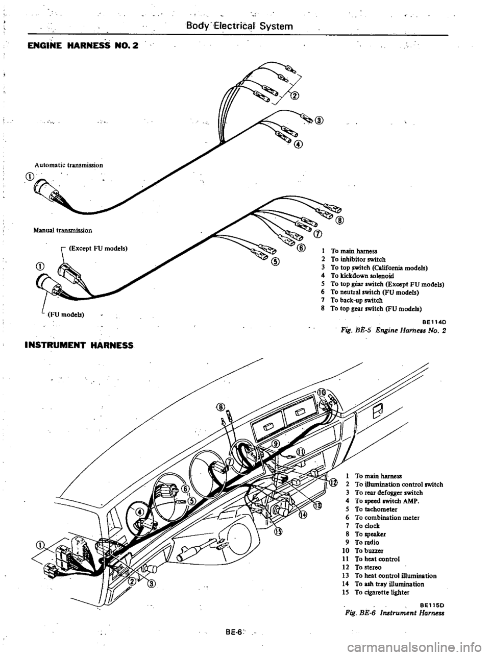
ENGINE
HARNESS
NO
2
@
Automatic
transmission
Manual
transmission
j
Except
FU
models
1
To
main
harness
2
To
inhibitor
switch
3
To
top
tch
California
models
4
To
kicJcdown
solenoid
5
To
top
gear
switch
Except
FU
models
6
To
neutral
switch
FU
models
7
To
back
up
switch
8
To
top
gear
switch
FU
models
BE1140
Fig
BE
5
Engine
Hame
No
2
INSTRUMENT
HARNESS
1
To
main
harness
2
To
illumination
control
switch
3
To
rear
defogger
switch
4
To
Ipeed
witch
AMP
5
To
tachometer
6
To
combination
meter
7
To
clock
8
To
speaker
9
To
radio
10
To
buzzer
11
To
heat
control
12
To
stereo
13
To
heat
control
illumination
14
To
ash
tray
illumination
15
To
cigarette
lighter
BE115D
Fig
BE
6
Instrument
Harne
BE
6
Page 454 of 548
Body
Electrical
System
ELECTRICAL
UNIT
OF
LIGHTING
SYSTEM
CAUTION
Before
starting
to
work
on
any
part
of
electrical
system
disconnect
battery
ground
cable
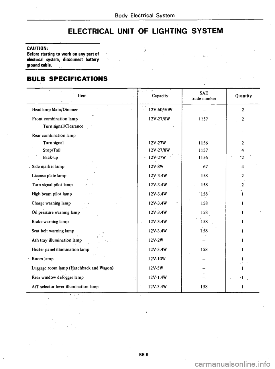
BULB
SPECIFICATIONS
Item
Headlamp
Main
Dilnmer
Front
combination
lamp
Turn
signal
Clearance
Rear
combination
lamp
Turn
signal
Stop
Tail
Back
up
Side
marker
lamp
License
plate
lamp
Turn
signal
pilot
lamp
High
beam
pilot
lamp
Charge
warning
lamp
Oil
pressure
warning
lamp
Brake
warning
lamp
Seat
belt
warning
lamp
Ash
tray
illumination
lamp
Heater
panel
illumination
laf
lp
Room
lamp
Luggage
room
lamp
Hatchback
and
Wagon
Rear
window
defogger
lamp
AfT
selector
lever
illumination
lamp
Capacity
SAE
trade
number
12V
60
50W
l2V
27
8W
1157
l2V
27W
12V
27
8W
12V
27W
12V
8W
l2V
3
4W
l2V
3
4W
l2V
3
4W
12V
3
4W
12V
3
4W
12V
3
4W
12V
3
4W
l2V2W
l2V
3
4W
l2V
lOW
Quantity
2
2
1156
2
1157
4
1156
2
67
4
158
2
158
2
158
158
158
158
158
158
l2V
5W
12V
14W
12V
3
4W
158
BE
9
Page 467 of 548
B6
Y
Electrica
System
f
EIIII
I
I
I
11111111
111
777
Rea
window
1
j
glass
W
777
n
1
r7
U
u
T
t
I
I
I
j
T
cD
t
ID
3
BE537
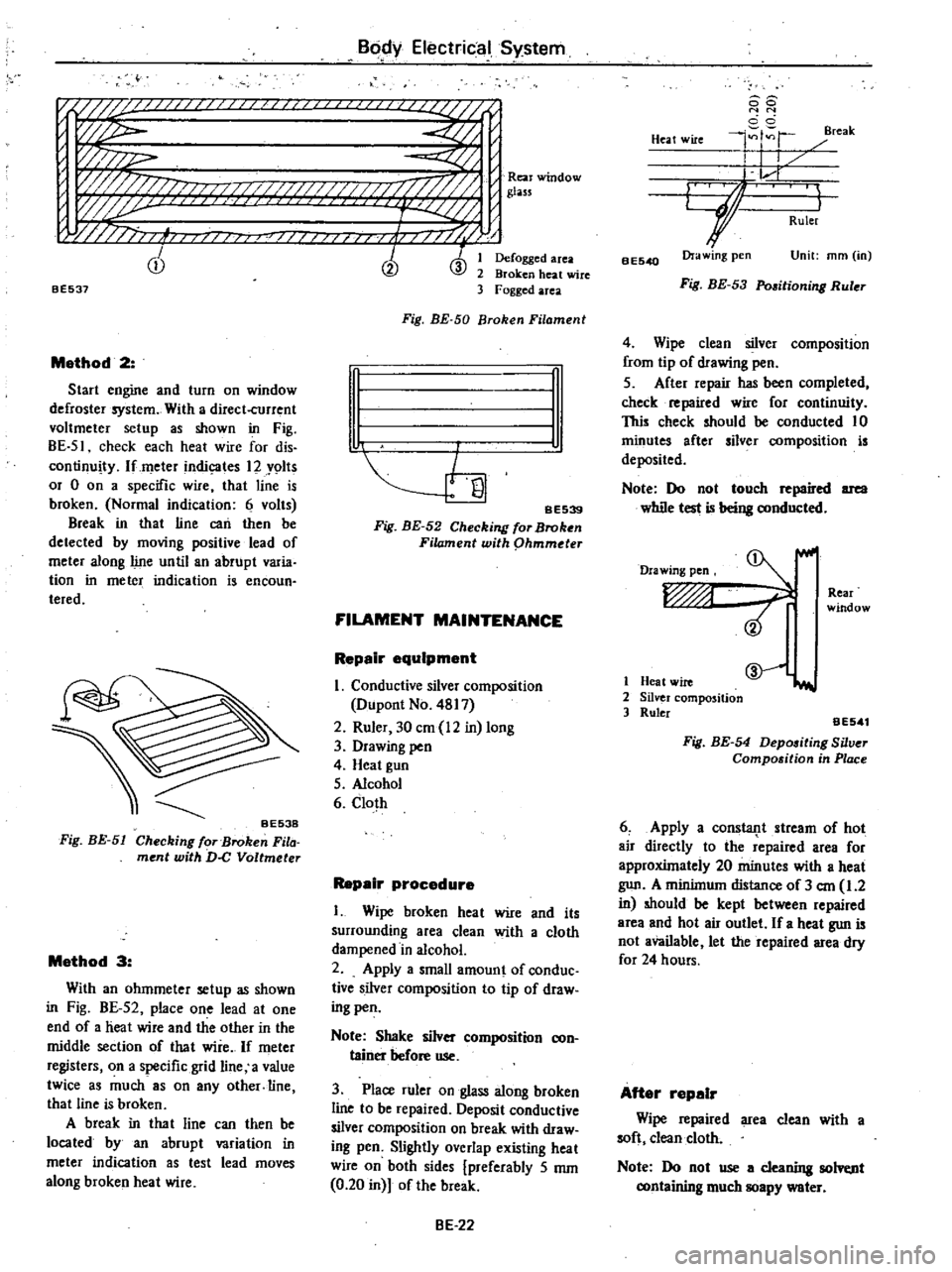
Method
2
Start
engine
and
turn
on
window
defroster
system
With
a
direct
current
voltmeter
setup
as
shown
in
Fig
BE
51
check
each
heat
wire
for
dis
continuity
lfmeter
indic
ates
12
Y9lts
or
0
on
a
specific
wire
that
line
is
broken
Normal
indication
6
volts
Break
in
that
line
can
then
be
detected
by
moving
positive
lead
of
meter
along
line
until
an
abrupt
varia
tion
in
meter
indication
is
encoun
teredo
Fig
BE
51
Method
3
With
an
ohmmeter
setup
as
shown
in
Fig
BE
52
place
one
lead
at
one
end
of
a
heat
wire
and
the
other
in
the
middle
section
of
that
wire
If
meter
registers
on
a
specific
grid
line
a
value
twice
as
much
8S
on
any
other
line
that
line
is
broken
A
break
in
tha
t
line
can
then
be
located
by
an
abrupt
variation
in
meter
indication
as
test
lead
moves
along
broken
heat
wire
Defogged
area
Broken
heat
wire
Fogged
area
Fig
BE
50
Broken
Filament
n
I
I
SE539
Fig
BE
52
Checking
for
Broken
Filament
with
phmmder
FILAMENT
MAINTENANCE
Repair
equipment
I
Conductive
silver
composition
Dupont
No
4817
2
Ruler
30
em
12
in
long
3
Drawing
pen
4
Heat
gun
5
Alcohol
6
Cloth
Repair
procedure
I
Wipe
broken
heat
wire
and
its
surrounding
area
clean
with
a
cloth
dampened
in
alcohol
2
Apply
a
small
amount
of
conduc
tive
silver
composition
to
tip
of
draw
ing
pen
Note
Shake
silver
composition
con
tainer
before
use
3
Place
ruler
on
glass
along
broken
line
to
be
repaired
Deposit
conductive
silver
composition
on
break
with
draw
ing
pen
Slightly
overlap
existing
heat
wire
on
both
sides
preferably
5
mm
0
20
in
of
the
break
BE
22
88
N
N
cci
4
r
reak
Heat
wire
I
I
L
r
GJ
I
Ruler
BE540
Ora
wing
pen
Unit
mm
in
Fig
BE
53
Pmitioning
Ruler
4
Wipe
clean
silver
composition
from
tip
of
drawing
pen
5
After
repair
has
been
completed
check
repaired
wire
for
continuity
This
check
should
be
conducted
10
minutes
after
silver
composition
is
deposited
Note
Do
not
touch
repaired
area
while
test
is
being
conducted
Drawing
pen
Rear
window
1
Heat
wire
2
Silver
composition
3
Ruler
@
iI
aE541
Fig
BE
54
Depositing
Silver
Compo
ition
in
Place
6
Apply
a
consla11t
stream
of
hot
air
directly
to
the
repaired
area
for
approxUnately
20
minutes
with
a
heat
gun
A
minilnum
distance
of
3
em
1
2
in
should
be
kept
between
repaired
area
and
hot
air
outlet
If
a
heat
gun
is
not
available
let
the
repaired
area
dry
for
24
hours
After
repair
Wipe
repaired
area
clean
with
a
soft
clean
cloth
Note
Do
not
use
a
cleaning
solvt
nt
containing
much
soapy
water
Page 475 of 548

WIPER
MOTOR
WINDSHIELD
WASHER
MOTOR
REAR
WIPER
MOTOR
REAR
WINDOW
WASHER
MOTOR
m
w
o
HORN
CIGARETTE
LIGHTER
CLOCK
HAZARD
FLASHER
LAMP
STOP
LAMP
ROOM
LAMP
LUGGAGE
ROOM
LAMP
TAIL
LAMP
CLEARANCE
LAMP
LICENSE
PLATE
LAMP
COMBINATION
METER
LAMP
l
I
ll
6
C
l
ii
en
g
0
o
m
till
oill
l
I
t1
l
CO
l
m
l
m
0
z
t
15A
10A
14
fA
20A
16
T
r
t1
l
t1
l
CO
CO
CJ
CJ
1
1
m
m
0
0
z
z
HEATER
lAIR
CONDITIONER
ENGINE
REVOLUTION
SWITCH
FUEL
CUT
SOLENOID
VACUUM
CUT
SOLENOID
AUTO
CHOKE
HEATER
THROTTLE
OPENER
SOLENOID
TURN
SIGNAL
LAMP
GAUGE
I
FUEL
L
WATER
TEMPERATURE
WARNING
LAMP
BRAKE
CHARGE
OIL
PRESSURE
SEAT
BELT
WARNING
BUZZER
BACK
UP
LAMP
KICKDOWN
SOLENOID
TACHOMETER
REAR
DEFOGGER
f
c
It
1
1
m
g
II
n
a
n
c
It
c
1J
c
CIl
z
G
S
3
OJ
o
Cl
m
CD
In
Ql