oil type DATSUN 610 1969 User Guide
[x] Cancel search | Manufacturer: DATSUN, Model Year: 1969, Model line: 610, Model: DATSUN 610 1969Pages: 171, PDF Size: 10.63 MB
Page 46 of 171
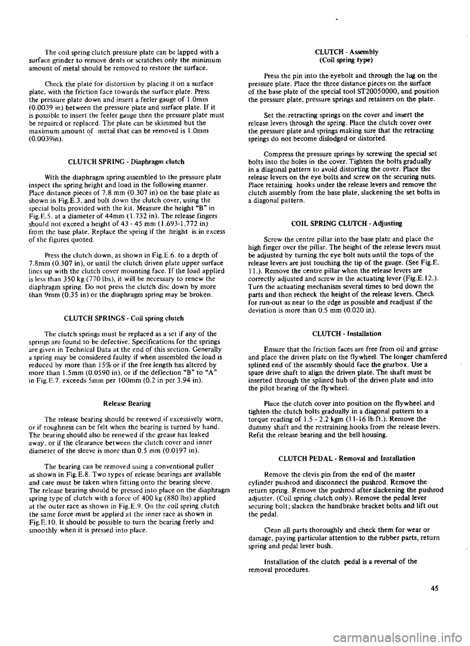
The
coil
spring
clutch
pressure
plate
can
be
lapped
with
a
surface
grinder
to
remove
dents
or
scratches
only
the
minimum
amount
of
metal
should
be
removed
to
restore
the
surface
Check
the
plate
for
distortion
by
placing
it
on
a
surface
plate
with
the
friction
face
towards
the
surface
plate
Press
the
pressure
plate
down
and
insert
a
feeler
gauge
of
1
0mm
0
0039
in
between
the
pressure
plate
and
surface
plate
If
it
is
possible
to
insert
the
feeler
gauge
then
the
pressure
plate
must
be
repaired
or
replaced
The
plate
can
be
skimmed
but
the
maximum
amount
of
metal
that
can
be
removed
is
1
0mm
0
0039in
CLUTCH
SPRING
Diaphragm
clutch
With
the
diaphragm
spring
assembled
to
the
pressure
plate
inspect
the
spring
height
and
load
in
the
following
manner
Place
distance
pieces
of
7
8
mm
0
307
in
on
the
base
plate
as
shown
in
Fig
E
3
and
bolt
down
the
clutch
cover
using
the
special
bolts
provided
with
the
kit
Meas
Jre
the
height
B
in
Fig
E
5
at
a
diameter
of
44mm
1
732
in
The
release
fingers
should
not
exceed
a
height
of
43
45
mm
1
693
1
772
in
from
the
base
plate
Replace
the
spring
if
the
height
is
in
excess
of
the
figures
quoted
Press
the
dutch
down
as
shown
in
Fig
E
6
to
a
depth
of
7
8mm
0
307
in
or
until
the
clutch
driven
plate
upper
surface
lines
up
with
the
clutch
cover
mounting
face
If
the
load
applied
is
less
than
350
kg
770
lbs
it
will
be
necessary
to
renew
the
diaphragm
spring
Do
not
press
the
clutch
disc
down
by
more
than
9mm
0
35
in
or
the
diaphragm
spring
may
be
broken
CLUTCH
SPRINGS
Coil
spring
clutch
The
clutch
springs
must
be
replaced
as
a
set
if
any
of
the
springs
are
found
to
be
defective
Specifications
for
the
springs
are
given
in
Technical
Data
at
the
end
of
this
section
Generally
a
spring
may
be
considered
faulty
if
when
assembled
the
load
is
reduced
by
more
than
15
or
if
the
free
length
has
altered
by
more
than
1
5mm
0
0590
in
or
if
the
deflection
B
to
A
in
Fig
E
7
exceeds
5mm
per
100mm
0
2
in
per
3
94
in
Release
Bearing
The
release
bearing
should
be
renewed
if
excessively
worn
or
if
roughness
can
be
felt
when
the
bearing
is
turned
by
hand
The
bearing
should
also
be
renewed
if
the
grease
has
leaked
away
or
if
the
clearance
between
the
clutch
cover
and
inner
diameter
of
the
sleeve
is
more
than
0
5
mm
0
0197
in
The
bearing
can
be
removed
using
a
conventional
puller
as
shown
in
Fig
E
8
Two
types
of
release
bearings
are
available
and
care
must
be
taken
when
fitting
onto
the
bearing
sleeve
The
release
bearing
should
be
pressed
into
place
on
the
diaphragm
spring
type
of
clutch
with
a
force
of
400
kg
880
lbs
applied
at
the
outer
race
as
shown
in
Fig
E
9
On
the
coil
spring
clutch
the
same
force
must
be
applied
at
the
inner
race
as
shown
in
Fig
E
IO
It
should
be
possible
to
turn
the
bearing
freely
and
smoothly
when
it
is
pressed
into
place
CLUTCH
Assembly
Coil
spring
type
Press
the
pin
into
the
eyebolt
and
through
the
lug
on
the
pressure
plate
Place
the
three
distance
pieces
on
the
surface
of
the
base
plate
of
the
special
tool
ST20050000
and
position
the
pressure
plate
pressure
springs
and
retainers
on
the
plate
Set
the
retracting
springs
on
the
cover
and
insert
the
release
levers
through
the
spring
Place
the
clutch
cover
over
the
pressure
plate
and
springs
making
sure
that
the
retracting
springs
do
not
become
dislodged
or
distorted
Compress
the
pressure
springs
by
screwing
the
special
set
bolts
into
the
holes
in
the
cover
Tighten
the
bolts
gradually
in
a
diagonal
pattern
to
avoid
distorting
the
cover
Place
the
release
levers
on
the
eye
bolts
and
screw
OR
the
securing
nuts
Place
retaining
hooks
under
the
release
levers
and
remove
the
clutch
assembly
from
the
base
plate
slackening
the
set
bolts
in
a
diagonal
pattern
COIL
SPRING
CLUTCH
Adjusting
Screw
the
centre
pillar
into
the
base
plate
and
place
the
high
finger
over
the
pillar
The
height
of
the
release
levers
must
be
adjusted
by
turning
the
eye
bolt
nuts
until
the
tops
of
the
release
levers
are
just
touching
the
tip
of
the
gauge
See
Fig
E
11
Remove
the
centre
pillar
when
the
release
levers
are
correctly
adjusted
and
screw
in
the
actuating
lever
Fig
E
12
Turn
the
actuating
mechanism
several
times
to
bed
down
the
parts
and
then
recheck
the
height
of
the
release
levers
Check
for
run
out
as
near
to
the
edge
as
possible
and
readjust
if
the
deviation
is
more
than
0
5
mrn
0
020
in
CLUTCH
InsWlation
Ensure
that
the
friction
faces
are
free
from
oil
and
grease
and
place
the
driven
plate
on
the
flywheel
The
longer
chamfered
splined
end
of
the
assembly
should
face
the
gearbox
Use
a
spare
drive
shaft
to
align
the
driven
plate
The
shaft
must
be
inserted
through
the
splined
hub
of
the
driven
plate
and
into
the
pilot
bearing
of
the
flywheel
Place
the
clutch
cover
into
position
on
the
flywheel
and
tighten
the
dutch
bolts
gradually
in
a
diagonal
pattern
to
a
torque
reading
of
1
5
2
2
kgm
11
16Ib
ft
Remove
the
dummy
shaft
and
the
restraining
hooks
from
the
release
levers
Refit
the
release
bearing
and
the
bell
housing
CLUTCH
PEDAL
Removal
and
Installation
Remove
the
clevis
pin
from
the
end
of
the
master
cylinder
pushrod
and
disconnect
the
pushrod
Remove
the
return
spring
Remove
the
pushrod
after
slackening
the
pushrod
adjuster
Coil
spring
clutch
only
Remove
the
pedal
lever
securing
bolt
slacken
the
handbrake
bracket
bolts
and
lift
out
the
pedal
Clean
all
parts
thoroughly
and
check
them
for
wear
or
damage
paying
particular
attention
to
the
rubber
parts
return
spring
and
pedal
lever
bush
Installation
of
the
clutch
pedal
is
a
reversal
of
the
removal
procedures
45
Page 51 of 171
other
end
of
the
tube
into
a
clean
container
partly
filled
with
brake
fluid
Top
up
the
master
cylinder
reservoir
with
recommended
fluid
and
open
the
bleed
screw
approximately
three
quarters
of
a
turn
Depress
the
clutch
pedal
slowly
and
hold
it
completely
down
re
tighten
the
bleed
screw
and
allow
the
pedal
to
return
slowly
Repeat
the
operation
until
the
fluid
emerging
from
the
tube
is
free
from
air
bubbles
It
should
be
noted
that
assistance
will
be
required
when
carrying
out
bleeding
operations
as
not
only
must
the
fluid
entering
the
glass
container
be
watched
but
also
the
clutch
pedal
has
to
be
operated
and
the
reservoir
topped
up
frequently
throughout
the
procedure
When
the
fluid
is
completely
free
from
air
bubbles
the
bleed
screw
should
be
retightened
on
a
down
stroke
of
the
pedal
Finally
remove
the
bleed
tube
and
replace
the
dust
cap
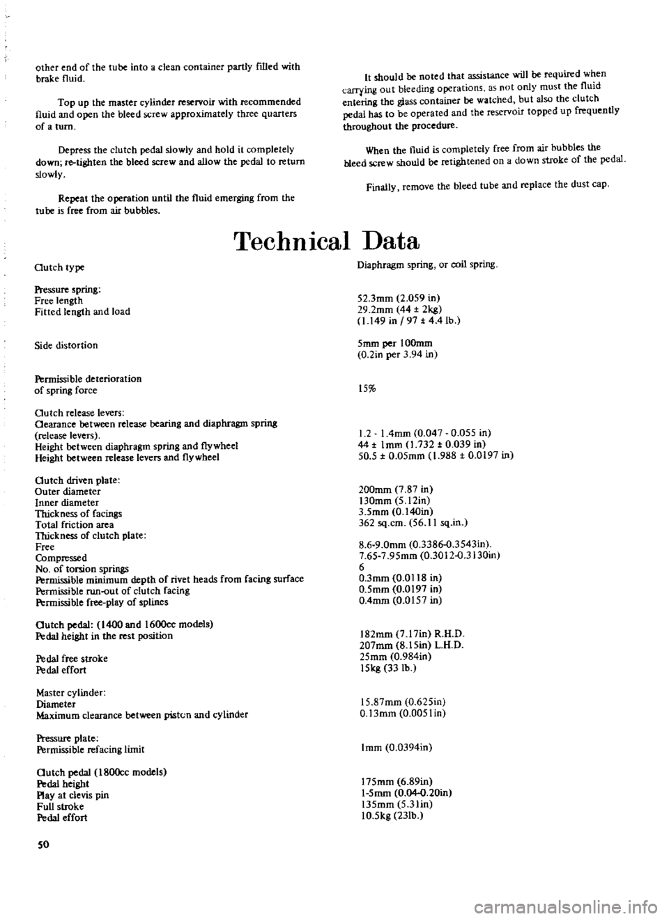
TechnIcal
Data
Outch
type
Pressure
spring
Free
length
Fitted
length
and
load
Side
distortion
Permissible
deterioration
of
spring
force
Outch
release
levers
Oearance
between
release
bearing
and
diaphragm
spring
release
levers
Height
between
diaphragm
spring
and
flywheel
Height
between
release
levers
and
flywheel
Outch
driven
plate
Outer
diameter
Inner
diameter
Thickness
of
facingS
Total
friction
area
TIrickness
of
clutch
plate
Free
Compressed
No
of
torsion
springs
Permissible
minimum
depth
of
rivet
heads
from
facing
surface
Permissible
run
out
of
clutch
facing
P
rmissible
free
play
of
splines
Outch
pedal
1400
and
1600cc
models
Pedal
height
in
the
rest
position
P
da1
free
stroke
P
da1
effort
Master
cylinder
Diameter
Maximum
clearance
between
piston
and
cylinder
Pressure
plate
Permissible
refacing
limit
Outch
pedal
180Occ
models
P
da1
height
Play
at
clevis
pin
Full
stroke
P
da1
effort
50
Diaphragm
spring
or
coil
spring
52
3mm
2
059
in
29
2mm
44
2kg
1
149
in
197
t
4
4
lb
5mm
per
IOOmm
0
2in
per
3
94
in
15
1
2
I
4mm
0
047
0
055
in
44
t
Imm
1
732
t
0
039
in
50
5
t
0
05mm
1
988
t
0
0197
in
200mm
7
87
in
130mm
5
12in
3
5mm
0
140in
362
sq
cm
56
11
sq
in
8
6
9
0mm
0
3386
o
3543in
7
65
7
95mm
0
3012
o
3130in
6
O
3mm
0
0118
in
0
5mm
0
0197
in
0
4mm
0
0157
in
182mm
7
17in
R
H
D
207mm
8
15in
L
H
D
25mm
0
984in
15kg
33
lb
15
87mm
0
625in
O
13mm
0
005lin
Imm
0
0394in
175mm
6
89in
1
5mm
0
04
0
20in
135mm
5
3lin
10
5kg
23Ib
Page 52 of 171
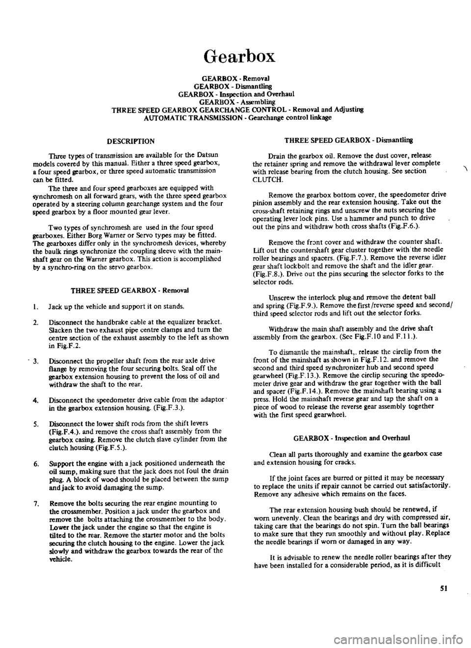
Gearbox
GEARBOX
Removal
GEARBOX
Dismantling
GEARBOX
Inspection
and
Overhaul
GEARBOX
Assembling
THREE
SPEED
GEARBOX
GEARCHANGE
CONTROL
Removal
and
Adjusting
AUTOMATIC
TRANSMISSION
Gearchange
control
linkage
DESCRIPTION
Three
types
of
transmission
are
available
for
the
Datsun
models
covered
by
this
manual
Either
a
three
speed
gearbox
a
four
speed
gearbox
or
three
speed
automatic
transmission
can
be
fitted
The
three
and
four
speed
gearboxes
are
equipped
with
nchromesh
on
all
forward
gears
with
the
three
speed
gearbox
operated
by
a
steering
column
gearchange
system
and
the
four
speed
gearbox
by
a
floor
mounted
gear
lever
Two
types
of
synchromesh
are
used
in
the
four
speed
gearboxes
Either
Borg
Warner
or
Servo
types
may
be
fitted
The
gearboxes
differ
only
in
the
synchromesh
devices
whereby
the
baulk
rings
synchronize
the
coupling
sleeve
with
the
main
shaft
gear
on
the
Warner
gearbox
This
action
is
accomplished
by
a
synchrcrring
on
the
servo
gearbox
THREE
SPEED
GEARBOX
Removal
I
Jack
up
the
vehicle
and
support
it
on
stands
2
Disconnect
the
hand
brake
cable
at
the
equalizer
bracket
Slacken
the
two
exhaust
pipe
centre
clamps
and
turn
the
centre
section
of
the
exhaust
assembly
to
the
left
as
shown
in
Fig
F
2
3
Disconnect
the
propeller
shaft
from
the
rear
axle
drive
flange
by
removing
the
four
securing
bolts
Seal
off
the
gearbox
extension
housing
to
prevent
the
loss
of
oil
and
withdraw
the
shaft
to
the
rear
4
Disconnect
the
speedometer
drive
cable
from
the
adaptor
in
the
gearbox
extension
housing
Fig
F3
S
Disconnect
the
lower
shift
rods
from
the
shift
levers
Fig
F
4
and
remove
the
cross
shaft
assembly
from
the
gearbox
casing
Remove
the
clutch
slave
cylinder
from
the
clutch
housing
Fig
F
5
6
Support
the
engine
with
ajack
positioned
underneath
the
oil
sump
making
sure
that
the
jack
does
not
foul
the
drain
plug
A
block
of
wood
should
be
placed
between
the
sump
and
jack
to
avoid
damaging
the
sump
7
Remove
the
bolts
securing
the
rear
engine
mounting
to
the
crossmember
Position
ajack
under
the
gearbox
and
remove
the
bolts
attaching
the
crossmember
to
the
body
Lower
the
jack
under
the
engine
so
that
the
engine
is
tilted
to
the
rear
Remove
the
starter
motor
and
the
bolts
securing
the
clutch
housing
to
the
engine
Lower
the
jack
slowly
and
withdraw
the
gearbox
towards
the
rear
of
the
vehicle
THREE
SPEED
GEARBOX
Dismantling
Drain
the
gearbox
oil
Remove
the
dust
cover
release
the
retainer
spring
and
remove
the
withdrawal
lever
complete
with
release
bearing
from
the
clutch
housing
See
section
CLUTCH
Remove
the
gearbox
bottom
cover
the
speedometer
drive
pinion
assembly
and
the
rear
extension
housing
Take
out
the
cross
shaft
retaining
rings
and
unscrew
the
nuts
securing
the
operating
lever
lock
pins
Use
a
hammer
and
punch
to
drive
out
the
pins
and
withdraw
both
cross
shafts
Fig
F
6
Remove
the
fr
mt
cover
and
withdraw
the
counter
shaft
Lift
out
the
countersbaft
gear
cluster
together
with
the
needle
roller
bearings
and
spacers
Fig
F
7
Remove
the
reverse
idler
gear
shaft
lock
bolt
and
remove
the
shaft
and
the
idler
gear
Fig
F
B
Drive
out
the
pins
securing
the
selector
forks
to
the
selector
rods
Unscrew
the
interlock
plug
and
remove
the
detent
ball
and
spring
Fig
F
9
Remove
the
first
reverse
speed
and
second
third
speed
selector
rods
and
lift
out
the
selector
forks
Withdraw
the
main
shaft
assembly
and
the
drive
shaft
assembly
from
the
gearbox
See
Fig
F
1O
and
F
11
To
dismantle
the
mainshaft
release
the
circlip
from
the
front
of
the
mainshaft
as
shown
in
Fig
F
12
and
remove
the
second
and
third
speed
synchronizer
hub
and
second
speed
gearwheel
Fig
F
13
Remove
the
circlip
securing
the
speedo
meter
drive
gear
and
withdraw
the
gear
together
with
the
ball
and
spacer
Fig
F
14
Remove
the
mainshaft
bearing
using
a
press
Hold
the
rnainshaft
reverse
gear
and
tap
the
shaft
on
a
piece
of
wood
to
release
the
reverse
gear
assembly
together
with
the
first
speed
gearwheel
GEARBOX
Inspection
and
Overhaul
Oean
all
parts
thoroughly
and
examine
the
gearbox
case
and
extension
housing
for
cracks
If
the
joint
faces
are
burred
or
pitted
it
may
be
necessary
to
replace
the
units
if
repair
cannot
be
carried
out
satisfactorily
Remove
any
adhesive
which
remains
on
the
faces
The
rear
extension
housing
bush
should
be
renewed
if
worn
unevenly
Clean
the
bearings
and
dry
with
compressed
air
taking
care
that
the
bearings
do
not
spin
Turn
the
ball
bearings
to
make
sure
that
they
run
smoothly
and
without
play
Replace
the
needle
bearings
if
worn
or
damaged
in
any
way
It
is
advisable
to
renew
the
needle
roller
bearings
after
they
have
been
installed
for
a
considerable
period
as
it
is
difficult
51
Page 56 of 171
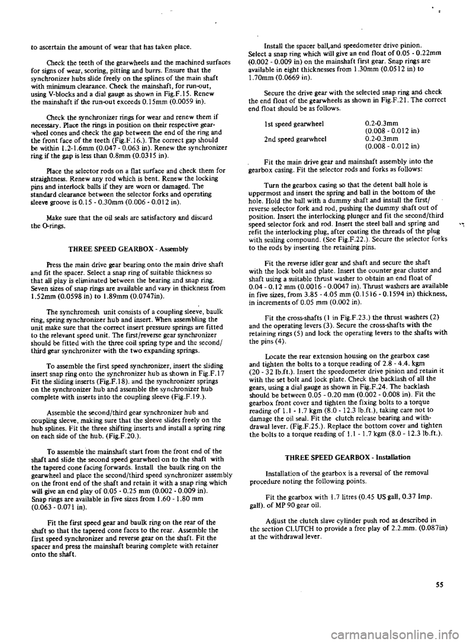
to
ascertain
the
amount
of
wear
that
has
taken
place
Check
the
teeth
of
the
gearwheels
and
the
machined
surfaces
for
signs
of
wear
scoring
pitting
and
burrs
Ensure
that
the
synchronizer
hubs
slide
freely
on
the
splines
of
the
main
shaft
with
minimum
clearance
Check
the
mainshaft
for
run
out
using
V
blocks
and
a
dial
gauge
as
shown
in
Fig
F
15
Renew
the
mainshaft
if
the
run
out
exceeds
0
15mm
0
0059
in
Check
the
synchronizer
rings
for
wear
and
renew
them
if
necessary
Place
the
rings
in
position
on
their
respective
gear
wheel
cones
and
check
the
gap
between
the
end
of
the
ring
and
the
front
face
of
the
teeth
Fig
F
16
The
correct
gap
should
be
within
1
2
1
6mm
0
047
0
063
in
Renew
the
synchronizer
ring
if
the
gap
is
less
than
0
8mm
0
0315
in
Place
the
selector
rods
on
a
flat
surface
and
check
them
for
traightness
Renew
any
rod
which
is
bent
Renew
the
locking
pins
and
interlock
balls
if
they
are
worn
or
damaged
The
standard
clearance
between
the
selector
forks
and
operating
sleeve
groove
is
0
15
0
30mm
0
006
0
012
in
Make
sure
that
the
oil
seals
are
satisfactory
and
discard
the
O
rings
THREE
SPEED
GEARBOX
Assembly
Press
the
main
drive
gear
bearing
onto
the
main
drive
shaft
and
fit
the
spacer
Select
a
snap
ring
of
suitable
thickness
so
that
all
play
is
eliminated
between
the
bearing
and
snap
ring
Seven
sizes
of
snap
rings
are
available
and
vary
in
thickness
from
1
52mm
0
0598
in
to
1
89mm
0
0747in
The
synchromesh
unit
consists
of
a
coupling
sleeve
baulk
ring
spring
synchronizer
hub
and
insert
When
assembling
the
unit
make
sure
that
the
correct
insert
pressure
springs
are
fitted
to
the
relevant
speed
unit
The
first
reverse
gear
synchronizer
should
be
fitted
with
the
three
coil
spring
type
and
the
second
third
gear
synchronizer
with
the
two
expanding
springs
To
assemble
the
fiI3t
speed
synchronizer
insert
the
sliding
insert
snap
ring
onto
the
synchronizer
hub
as
shown
in
Fig
F
17
Fit
the
sliding
inserts
Fig
F
18
and
the
synchronizer
springs
on
the
synchronizer
hub
and
assemble
the
synchronizer
hub
complete
with
inserts
into
the
coupling
sleeve
Fig
F
19
Assemble
the
second
third
gear
synchronizer
hub
and
coupling
sleeve
making
sure
that
the
sleeve
slides
freely
on
the
hub
splines
Fit
the
three
shifting
inserts
and
install
a
spring
ring
on
each
side
of
the
hub
Fig
F
20
To
assemble
the
mainshaft
start
from
the
front
end
of
the
shaft
and
slide
the
second
speed
gearwheel
on
to
the
shaft
with
the
tapered
cone
facing
forwards
Install
the
baulk
ring
on
the
gearwheel
and
place
the
second
third
speed
synchronizer
assembly
on
the
front
end
of
the
shaft
and
retain
it
with
a
snap
ring
which
will
give
an
end
play
of
0
05
0
25
mm
0
002
0
009
in
Snap
rings
are
available
in
five
sizes
from
1
60
1
80
mm
0
063
0
071
in
Fit
the
first
speed
gear
and
baulk
ring
on
the
rear
of
the
shaft
so
that
the
tapered
cone
faces
to
the
rear
Assemble
the
first
speed
synchronizer
and
reverse
gear
on
the
shaft
Fit
the
spacer
and
press
the
mainshaft
bearing
complete
with
retainer
onto
the
shaft
Install
the
spacer
ball
and
speedometer
drive
pinion
Select
a
snap
ring
which
will
give
an
end
float
of
0
05
0
22mm
0
002
0
009
in
on
the
mainshaft
first
gear
Snap
rings
are
available
in
eight
thicknesses
from
1
30mrn
0
0512
in
to
1
70mm
0
0669
in
Secure
the
drive
gear
with
the
selected
snap
ring
and
check
the
end
float
of
the
gearwheels
as
shown
in
Fig
F
21
The
correct
end
float
should
be
as
follows
I
st
speed
gearwheel
0
2
o
3mm
0
008
0
012
in
0
2
0
3mm
0
008
0
012
in
2nd
speed
gearwheel
Fit
the
main
drive
gear
and
mainshaft
assembly
into
the
gearbox
casing
Fit
the
selector
rods
and
forks
as
follows
Turn
the
gearbox
casing
so
that
the
detent
ball
hole
is
uppermost
and
insert
the
spring
and
ball
in
the
bottom
of
the
hole
Hold
the
ball
witb
a
dummy
shaft
and
install
tbe
first
reverse
selector
fork
and
rod
pushing
the
dummy
shaft
out
of
position
Insert
the
interlocking
plunger
and
fit
the
second
third
speed
selector
fork
and
rod
Insert
the
steel
ball
and
spring
and
refit
the
interlocking
plug
after
coating
the
threads
of
the
plug
with
sealing
compound
See
Fig
F
22
Secure
the
selector
forks
to
the
rods
by
inserting
the
retaining
pins
Fit
the
reverse
idler
gear
and
shaft
and
secure
the
shaft
with
the
lock
bolt
and
plate
Insert
the
counter
gear
cluster
and
shaft
using
a
suitable
thrust
washer
to
obtain
an
end
float
of
0
04
0
12
mm
0
0016
0
0047
in
Thrust
washers
are
available
in
five
sizes
from
3
85
4
05
mm
0
1516
0
1594
in
thickness
in
increments
of
0
05
mm
0
002
in
Fit
the
cross
shafts
1
in
Fig
F
23
the
thrust
washers
2
and
the
operating
levers
3
Secure
the
cross
shafts
with
the
retaining
rings
5
and
lock
the
operating
levers
to
the
shafts
with
the
pins
4
Locate
the
rear
extension
housing
on
the
gearbox
case
and
tighten
the
bolts
to
a
torque
reading
of
2
8
4
4
kgm
20
32
Ib
ft
Insert
the
speedometer
drive
pinion
and
retain
it
with
the
set
bolt
and
lock
plate
Check
the
backlash
of
all
the
gears
using
a
dial
gauge
as
shown
in
Fig
F
24
The
backlash
should
be
between
0
05
0
20
mm
0
002
0
008
in
Fit
the
gearbox
front
cover
and
tighten
the
fixing
bolts
to
a
torque
reading
of
1
I
1
7
kgm
8
0
12
3
lb
ft
taking
care
not
to
damage
the
oil
seal
Fit
the
clutch
release
bearing
and
with
drawallever
Fig
F
25
Replace
the
bottom
cover
and
tighten
the
bolts
to
a
torque
reading
of
1
I
1
7
kgm
8
0
12
31b
ft
THREE
SPEED
GEARBOX
Installation
Installation
of
the
gearbox
is
a
reversal
of
the
removal
procedure
noting
the
following
points
Fit
the
gearbox
with
I
7
litre
0
45
US
gall
0
37
Imp
gall
of
MP
90
gear
oil
Adjust
the
clutch
slave
cylinder
push
rod
as
described
in
the
section
CLUTCH
to
provide
a
free
play
of
2
2
mm
0
087in
at
the
withdrawal
lever
55
Page 58 of 171
FOUR
SPEED
GEARBOX
Removal
and
Installation
The
removal
and
installation
procedures
for
the
four
speed
gearbox
are
similar
to
those
previously
described
for
the
three
speed
gearbox
However
the
floor
mounted
gear
lever
must
be
removed
from
the
controllevef
bracket
in
addition
to
the
operations
already
detailed
FOUR
SPEED
GEARBOX
Dismantling
Drain
the
oil
from
the
gearbox
Remove
the
dust
coveT
and
release
the
spring
securing
the
clutch
withdrawal
lever
Remove
the
withdrawal
lever
and
release
bearing
from
the
clutch
housing
as
described
in
the
section
CLurCH
Remove
the
clevis
pin
securing
the
striking
rod
to
the
control
lever
Remove
the
speedometer
drive
pinion
assembly
and
with
draw
the
rear
extension
housing
Disengage
the
striking
rod
from
the
selector
rod
gates
Remove
the
gearbox
covers
See
Figs
F
26
and
F
27
Unscrew
the
three
detent
ball
plugs
and
remove
the
spriags
and
detent
balls
Drive
out
the
pins
securing
the
selector
forks
to
the
rods
and
withdraw
the
forks
and
rods
Lock
the
main
shaft
by
moving
the
first
second
and
third
fourth
coupling
sleeve
into
gear
at
the
same
time
and
release
the
ffiainshaft
nut
Remove
the
countershaft
and
the
gear
cluster
together
with
the
two
needle
roller
bearings
and
spacers
Remove
the
snap
ring
holding
the
revep
e
idler
gear
and
withdraw
the
reverse
idler
gears
and
shaft
Fig
F
28
Take
off
the
bolts
securing
the
mainshaft
bearing
retainer
to
the
gearbox
case
Fig
F
29
Withdraw
the
mainshaft
assembly
Fig
F
30
and
the
main
drive
shaft
The
mainshaft
can
be
dismantled
in
the
following
manner
Release
the
third
fourth
synchronizer
unit
snap
ring
and
with
draw
the
hub
complete
with
coupling
sleeve
Remove
the
third
speed
gearwheel
and
the
needle
roller
bearing
from
the
main
shaft
Take
off
the
mainshaft
nut
and
locking
plate
Remove
the
speedometer
drive
gear
with
the
retaining
ball
Withdraw
the
mainshaft
reverse
gear
and
the
hub
Press
off
the
mainshaft
bearing
complete
with
the
bearing
retainer
Remove
the
thrust
washer
and
the
first
speed
gear
together
with
the
needle
roller
bearing
taking
care
not
to
lose
the
small
baU
used
to
locate
the
thrust
washer
Slide
off
the
first
speed
gearwheel
bush
Withdraw
the
first
second
synchronizer
and
hub
Remove
the
second
speed
gearwheel
and
needle
roller
bearing
FOUR
SPEED
GEARBOX
Installation
Refer
to
the
instructions
given
for
the
three
speed
gearbox
and
to
Technical
Data
for
the
specifications
applicable
to
the
different
gearboxes
FOUR
SPEED
GEARBOX
Assembly
Assembly
of
the
gearbox
is
similar
to
the
procedures
previously
described
for
the
three
speed
gearbox
with
the
following
exceptions
When
assembling
the
main
drive
gear
bearing
on
the
shaft
insiall
the
spacer
and
select
a
new
snap
ring
to
eliminate
all
end
float
between
bearing
and
snap
ring
Snap
rings
are
available
in
five
thicknesses
from
1
52
1
77mm
0
06
0
07
in
The
assembly
procedures
for
the
Warner
type
synchronizers
are
similar
to
the
instructions
previously
described
for
the
three
speed
gearbox
Refer
to
THREE
SPEED
GEARBOX
Assembly
for
further
details
To
assemble
the
Servo
F4C63
type
synchronizers
proceed
as
follows
Place
the
gear
on
a
clean
flat
surface
and
install
the
synchronizer
ring
on
the
inner
side
of
theclutch
gear
Fit
the
thrust
block
into
place
as
shown
in
Fig
F
31
Place
the
anchor
block
and
brake
band
into
position
and
fit
the
circlip
into
the
groove
in
the
gear
to
secure
the
synchromesh
assembly
When
assembling
the
mainshaft
select
a
snap
ring
which
will
give
an
end
float
between
0
05
0
15
mm
0
002
0
006in
to
the
third
speed
gearwheel
Snap
rings
are
available
in
five
sizes
from
1
40
mm
0
0551
in
to
1
60
mm
0
0630
in
thick
ness
Tighten
the
locknut
at
the
rear
of
the
mainshaft
to
a
torque
reading
of
7
1
kgm
51
87Ib
ft
Assemble
the
reverse
idler
gear
as
shown
in
Fig
F
32
The
reverse
idler
driven
gear
3
should
be
placed
on
the
end
of
the
reverse
shaft
1
with
the
longest
spline
and
retained
with
a
suitable
snap
ring
2
Install
the
reverse
shaft
and
gear
assembly
into
the
gearbox
case
from
the
rear
with
the
thrust
washer
4
between
the
gear
and
the
case
Fit
the
thrust
washer
5
and
idler
gear
6
18
teeth
and
secure
with
a
suitable
snap
ring
2
The
end
float
of
the
gear
should
be
checked
and
adjusted
to
0
1
O
3mm
0
004
0
012
in
by
selecting
a
suitable
snap
ring
2
Five
thicknesses
of
snap
rings
are
available
from
I
lmm
0
043in
to
1
5mm
0
06in
See
Technical
Data
for
F4W63
and
F4C63
gearboxes
Adjust
the
counter
gear
end
float
to
0
05
0
15
mm
0
002
0
006in
by
selecting
a
thrust
washer
of
the
required
thickness
Thrust
washers
are
available
in
five
thicknesses
from
2
40
2
60
mm
0
094
0
102
in
When
assembling
the
selector
mechanisms
Fig
F
33
fit
the
first
second
selector
forks
I
and
the
third
fourth
selector
forks
2
onto
the
coupling
sleeves
and
insert
the
first
second
fork
rod
3
Fit
an
interlock
plunger
4
and
the
third
fourth
speed
selector
rod
5
Do
not
forget
the
interlock
pin
7
A
section
through
the
selector
and
interlock
mechanism
is
given
in
Fig
F
34
Install
an
interlock
plunger
6
and
assemble
the
reverse
selector
fork
8
and
fork
rod
9
Secure
the
selector
forks
to
the
rods
with
the
retaining
pins
10
Place
a
check
ball
and
spring
into
each
of
the
holes
and
screw
the
plug
down
to
a
torque
reading
of
1
7
2
1
Jegm
12
3
15
2
Ib
ft
after
coating
the
threads
with
sealing
com
pound
Install
the
rear
extension
housing
engaging
the
striking
rod
with
the
fork
rod
gates
and
tighten
the
housing
bolts
to
a
torque
reading
of
1
6
2
5
kgm
12
18Ib
ft
Fit
the
front
and
bottom
covers
and
tighten
the
bolts
to
a
torque
reading
of
1
1
1
8
kgm
8
13Ib
ft
57
Page 83 of 171

REAR
SHOCK
ABSORBERS
Replacing
Estate
cars
and
Vans
Jack
up
the
reaT
of
the
vehicle
and
place
stands
under
the
rear
axle
housing
Disconnect
the
lower
end
of
the
rear
shock
absorber
from
the
spring
seat
Fig
H
23
Remove
the
shock
absorber
upper
attachment
nuts
and
withdraw
the
shock
absorber
The
upper
attachment
nuts
are
located
behind
the
Tear
seat
backrest
as
shown
in
Fig
H
24
Check
the
shock
absorber
for
leakage
or
cracks
and
make
sure
that
the
shaft
is
straight
Inspect
the
rubber
bushings
for
damage
and
deterioration
Renew
all
defective
components
lnstallation
is
a
reversal
of
the
removal
procedures
Tighten
the
upper
and
lower
shock
absorber
attachment
nuts
to
the
torque
readings
stipulated
in
TIGlITENING
TORQUES
NOTE
The
weight
of
the
vehicle
must
be
resting
on
the
fear
wheels
when
tightening
the
lower
mounting
to
damp
the
rubber
bushes
in
an
unloaded
position
TechnICal
Data
I
Type
Independent
suspension
with
semi
tralllI1g
arms
or
semi
floating
COIL
SPRINGS
14
2mm
0
559
in
14
5mm
0
571
in
90
mm
3
543
in
306
mm
12
047
in
299
mm
II
772
in
290
mm
11417
in
I
1400
and
1600cc
Wire
diameter
Wire
diameter
hard
suspension
Coil
diameter
Free
length
R
H
Free
length
L
H
Free
length
Hard
suspension
1800cc
Wire
diameter
Coil
diameter
Free
length
RHD
R
H
Free
length
RHD
L
H
Free
length
LHD
both
Free
length
Hard
suspension
RHD
R
H
RHD
L
H
LHD
both
14
5
mm
0
571
in
90
3
54
in
321
mm
12
6
in
307
mm
12
1
in
321
mm
12
6
in
306
mm
12
0
in
299
mm
I
1
8
in
306
mm
12
0
in
SHOCK
ABSORBERS
34
56
kg
75
123
lb
21
39
kg
46
86
lb
SHOCK
ABSORBERS
Estate
cars
and
Vans
1400
and
1600cc
estate
cars
and
rigid
axle
sedan
Piston
diameter
2S
mm
0
984
in
Stroke
205
mm
8
071
in
Max
length
518
mm
20
39
in
Damping
force
at
0
3
in
see
Estate
cars
Expansion
Compression
Damping
force
at
0
3m
jsec
Sedan
Expansion
Compression
1400
and
1600
cc
Piston
diameter
Piston
diameter
Hard
suspension
Stroke
Max
length
Damping
force
at
0
3m
sec
Expansion
Compression
1800
cc
Stroke
Max
lengtb
Damping
force
at
0
3
m
sec
Expansion
Compression
82
35
mm
1
378
in
40
mm
1
575
in
206
mm
8
110
in
568
mm
22
362
in
45
kg
99
21b
28
kg
61
7
lb
220
mm
8
60
in
595
mm
23
4
in
90
kg
198
4
lb
50
kg
110
3
lb
75
kg
165
4Ib
40
kg
88
2
lb
1800cc
Estate
cars
Stroke
Max
length
Damping
force
at
O
3m
sec
Estate
cars
Expansion
Compression
205mm
8
071
in
518
mm
20
39
in
63
87
kg
139
192
lb
33
43
kg
73
95
lb
Damping
force
at
0
3
m
sec
Estate
car
and
Van
with
hard
suspension
Expansion
Compression
97
131
kg
214
289
lb
29
43
kg
64
95
lb
REAR
SPRINGS
1400
and
1600cc
Estate
car
Length
Width
Thickness
No
of
leaves
Free
camber
Laden
camber
1200mm
47
2
in
60
mm
f2
362
in
6
mm
0
236
in
4
137
mm
5
394
in
15
mm
265
kg
0
59
in
584
lb
Spring
eye
bolt
diameter
Front
Rear
45
mm
I
772
in
30
mm
U81
in
1400
and
1600
cc
Free
camber
Laden
cam
her
rigid
axle
sedan
100
mm
3
937
in
15mm
250
kg
0
591
in
551
lb
1800cc
Estate
Laden
camber
Turning
torque
15
mm
265
kg
0
591
in
1
584
lb
2
2
kg
mm
123
Ib
in
REAR
AXLE
SHAFT
less
than
4
5
kg
cm
3
91b
in
less
than
0
1
S
mm
0
006
in
DRIVE
SHAFT
AND
JOURNAL
Spring
constant
End
play
Sliding
resistance
1400
and
1600
cc
Sliding
resistance
1800cc
0
15
kg
0
33
lib
less
than
20
kg
44
lb
Radial
play
of
ball
spline
less
than
O
lmm
0
004
in
Page 84 of 171
Front
SuspensIon
DESCRIPTION
WHEEL
HUBS
WHEEL
BEARINGS
Adjusting
FRONT
AXLE
AND
SUSPENSION
ASSEMBLY
DESCRIPTION
The
front
suspension
is
of
the
strut
type
with
the
coil
spring
and
hydraulic
damper
units
mounted
on
the
suspension
member
and
transverse
link
assembly
See
FigJ
1
Vertical
movement
of
the
suspension
is
controlled
by
the
strut
assembly
the
tension
rod
absorbs
the
forward
and
backward
movement
of
the
transverse
links
whilst
side
move
ment
of
the
body
is
controlled
by
the
stabilizer
rod
which
is
attached
to
the
body
and
transverse
links
WHEEL
HUBS
Removal
1
Jack
up
the
vehicle
remove
the
road
wheel
and
disconnect
the
brake
hose
at
the
strut
outer
casing
bracket
as
described
under
the
previous
heading
Plug
the
opened
end
of
the
hose
to
prevent
loss
of
fluid
2
Remove
the
brake
calliper
assembly
or
the
brake
drum
as
described
in
the
section
BRAKES
3
Remove
the
grease
cap
from
the
hub
by
tapping
lightly
at
the
joint
using
a
screwdriver
and
hammer
4
Withdraw
the
cotter
pin
from
the
wheel
bearing
locknut
and
remove
the
nut
Remove
the
wheel
hub
together
with
the
wheel
bearing
and
washer
Fig
J
2
On
cars
fitted
with
disc
brakes
the
hub
is
removed
complete
with
brake
disc
5
The
wheel
bearing
outer
race
can
be
removed
from
the
hub
using
a
drift
as
shown
in
Fig
I
3
WHEEL
HUBS
Inspection
and
Overhaul
Gean
the
hub
and
bearings
by
washing
in
petrol
Examine
the
grease
seal
and
make
sure
that
it
is
not
worn
or
cracked
renew
the
seal
if
necessary
Ensure
that
the
races
are
not
pitted
or
scored
rotate
them
and
check
for
signs
of
wear
and
play
A
sectional
view
of
the
wheel
bearing
assembly
is
given
in
Fig
14
to
provide
an
indication
of
the
points
to
be
checked
WHEEL
HUB
AND
BEARING
Installation
The
wheel
bearing
outer
race
can
be
refitted
with
a
suitable
drift
or
special
tool
ST
35310000
Fill
the
wheel
hub
and
the
hub
cap
to
the
positions
shown
in
Fig
J
5
with
multi
purpose
grease
Fill
the
spaces
between
the
bearing
rollers
and
the
lip
of
the
grease
seal
with
the
same
type
of
grease
Lightly
smear
the
spindle
shaft
and
threads
the
bearing
washer
and
bearing
lock
SPRING
AND
STRUT
ASSEMBLY
TRANSVERSE
LINK
AND
LOWER
BALL
JOINT
FRONT
WHEEL
ALIGNMENT
ADJUSTING
THE
STEERING
ANGLE
nut
with
grease
and
assemble
the
parts
onto
the
wheel
spindle
Make
sure
that
dirt
and
foreign
matter
does
not
adhere
to
the
greased
surfaces
Adjust
the
wheel
bearings
as
described
under
the
following
heading
WHEEL
BEARINGS
Adjusting
The
wheel
bearings
can
be
adjusted
with
the
road
wheel
the
hub
cap
and
the
bearing
locknut
cotterpin
removed
as
previously
described
Tighten
the
wheel
bearing
locknut
to
a
torque
reading
of
3
0
3
5
kgm
21
7
25
3lb
ft
Turn
the
hub
several
times
in
each
direction
to
settle
the
bearing
and
then
retighten
the
bearing
locknut
to
the
specified
torque
reading
Slacken
the
bearing
locknut
to
an
angle
between
40
to
700
a
ay
from
the
previously
tightened
position
and
align
the
cotter
pin
hole
with
the
hole
in
the
spindle
Turn
the
wheel
hub
a
few
times
in
each
direction
and
then
measure
the
torque
required
to
cause
the
hub
to
turlI
A
spring
balance
should
be
used
as
shown
m
Rig
J
p
make
sure
that
the
brake
pads
are
not
binding
on
the
disc
type
of
brake
unit
and
check
that
the
force
required
to
turn
the
hub
is
within
the
following
fIgures
Wheel
bearing
rotation
starting
torque
1800ce
With
new
bearing
7
0
kg
cm
97
in
oz
1400
1600cc
With
new
bearing
8
0
kg
cm
111
2
in
oz
With
used
bearing
4
0
kg
cm
56
0
in
oz
Starting
torque
at
the
hub
bolt
lWth
new
bearing
ith
used
bearings
1
57
kg
3
46
lb
0
7
kg
1
541b
Adjust
the
locknut
slightly
if
the
fIgures
do
not
conform
and
replace
the
cotterpin
Refit
the
hub
cap
and
the
road
wheel
FRONT
AXLE
AND
SUSPENSION
ASSEMBLY
Removal
Jack
up
the
front
of
the
vehicle
and
place
stands
under
the
ront
side
members
Remove
the
road
wheels
and
the
splash
board
3
Disconnect
the
front
brake
hoses
and
remove
the
brake
hose
locking
springs
Withdraw
the
plates
and
remove
the
hoses
from
the
strut
assembly
Plug
the
ends
of
the
hoses
to
prevent
the
ingress
of
dirt
and
loss
of
fluid
4
Remove
the
cotter
pin
from
the
tie
rod
ball
joint
remove
83
Page 92 of 171
SteerIng
DEsn
IPTION
S
i
EERlNG
MaintenaDce
STEERING
WHEEL
AND
STEERING
GEAR
Removal
and
Installation
STEERING
GEAR
Dismantling
STEERING
GEAR
Inspection
and
Adjustment
DESCRIPTION
A
worm
and
recirculating
ball
type
steering
system
is
fitted
to
the
vehicle
the
component
parts
of
the
steering
gear
are
shown
in
Fig
K
I
The
steering
linkage
consists
of
the
centre
tie
rod
pitman
ann
idler
arm
outer
tie
rods
and
the
knuckle
arms
as
shown
in
Fig
K
2
A
collapsible
steering
column
assembly
can
be
fitted
to
the
vehicle
to
protect
the
driver
from
injury
in
a
head
on
collision
Details
of
this
type
of
assembly
are
given
under
the
appropriate
heading
STEERING
Maintenance
O1eck
the
oil
level
in
the
steering
box
every
10
000
km
6
000
miles
and
top
up
with
recommended
lubricant
if
necessary
Grease
the
steering
linkage
every
50
000
km
30
OOO
miles
It
will
be
necessary
to
replace
the
plug
in
the
tie
rod
ball
joints
with
a
grease
nipple
for
this
operation
as
previously
described
in
the
section
FRONT
SUSPENSION
Use
a
grease
gun
to
completely
replace
the
old
grease
with
new
grease
making
SUfe
that
the
grease
is
not
forced
from
under
the
cover
clamp
if
a
high
pressure
gun
is
used
STEERING
WHEEL
AND
STEERING
GEAR
Removal
1
Take
out
the
retaining
bolts
and
remove
the
horn
ring
remove
the
steering
wheel
nut
Fig
K
3
and
pull
off
the
steering
wheel
The
special
tool
ST
27180000
should
be
used
if
available
2
Disconnect
the
battery
leads
remove
the
steering
column
shell
covers
and
the
turn
signal
and
lighting
switch
assembly
3
On
vehicles
fitted
with
steering
column
gear
change
assemblies
the
gear
lever
must
be
removed
from
the
control
rod
assembly
Unscrew
the
retaining
boltg
and
disconnect
the
gear
lever
4
Remove
the
bolts
from
the
steering
column
upper
clamp
Fig
K
4
and
the
bolts
holding
the
lower
plate
Fig
K
5
5
If
the
vehicle
is
fitted
with
steering
column
gear
change
remove
the
cotterpin
from
the
trunnion
and
detach
the
gearchange
rod
and
selector
rod
from
the
change
lever
and
selector
lever
STEERING
GEAR
Assembly
and
Adjustment
COLLAPSIBLE
STEERING
COLLAPSIBLE
STEERING
Removal
and
Inspection
COLLAPSIBLE
STEERING
Installation
STEERING
LINKAGE
6
Remove
the
bolts
securing
the
steering
gear
housing
to
the
car
body
Fig
K
6
and
pull
the
steering
gear
towards
the
engine
compartment
Remove
the
gearchange
control
from
the
steering
gear
assembly
as
described
in
the
section
GEARBOX
STEERING
WHEEL
AND
STEERING
GEAR
Installation
Installation
is
a
reversal
of
the
removal
procedure
When
the
installation
has
been
completed
make
sure
that
the
steering
wheel
can
be
turned
smoothly
and
is
correctly
aligned
The
free
travel
of
the
steering
wheel
should
be
between
2S
30mm
0
9B
1
18
in
Tighten
the
steering
wheel
locknut
to
a
torque
reading
of
4
0
5
0
kgm
29
36Ib
ft
and
the
steering
column
upper
clamp
and
plate
bolts
to
a
torque
reading
of
1
3
1
8
kgm
94
1
3
Ib
ft
Ensure
that
the
steering
box
is
topped
up
to
the
correct
level
with
recommended
lubricant
STEERING
GEAR
Dismantling
Remove
the
pitman
arm
retaining
nut
and
pull
out
the
arm
The
special
puller
ST
27140000
should
be
used
if
available
Remove
the
drain
plug
from
the
steering
gear
housing
and
drain
the
oil
Slacken
the
adjusting
screw
nut
and
turn
the
sector
shaft
adjusting
screw
a
few
turns
in
the
anti
clockwise
direction
Remove
the
sector
shaft
cover
retaining
bolts
and
pull
the
sector
shaft
cover
and
sector
shaft
from
the
gear
housing
Fig
K
7
Remove
the
bolts
securing
the
column
jacket
to
the
gear
housing
and
carefully
withdraw
the
main
column
jacket
assembly
from
the
gear
housing
Fig
K
B
NOTE
The
ball
must
not
be
allowed
to
run
to
either
end
of
the
worm
or
the
ends
of
the
ball
guides
will
be
damaged
Pull
the
column
assembly
from
the
column
jacket
Remove
the
sector
shaft
oil
seal
and
take
out
the
rear
bearing
outer
race
from
the
column
jacket
with
a
suitable
puller
Withdraw
the
bearing
inner
races
from
the
front
and
fear
worm
bearings
Remove
the
column
shaft
bearing
91
Page 110 of 171
ElectrIcal
EquIpment
DESCRIPTION
BATTERY
Maintenance
STARTER
MOTOR
Removal
and
Dismantling
STARTER
MOTOR
Testing
STARTER
MOTOR
Assembly
and
Installation
ALTERNATOR
Removal
Dismantling
and
Inspection
DESCRIPTION
A
12
volt
negative
earth
electrical
system
is
used
in
which
the
battery
is
charged
by
an
alternator
In
the
alternator
a
magnetic
field
is
produced
by
the
rotor
which
consists
of
the
alternator
shaft
field
coil
p
le
pieces
and
slip
rings
Output
current
is
generated
in
the
armature
coils
located
in
the
stator
Six
silicon
diodes
are
incorporated
in
the
alternator
caSing
to
rectify
the
alternating
current
supply
A
voltage
regulator
and
pilot
lamp
relay
are
built
in
the
regulator
box
which
nonnally
does
not
give
trouble
or
require
attention
The
starter
motor
is
a
brush
type
series
wound
motor
in
which
positive
meshing
of
the
pinion
and
ring
gear
teeth
are
secured
by
means
of
an
overrunning
clutch
BATTERY
Maintenance
The
battery
should
be
maintained
in
a
clean
and
dry
condition
at
all
times
or
a
current
leakage
may
occur
between
the
terminals
If
frequent
topping
up
is
required
it
is
an
indication
of
overcharging
or
deterioration
of
the
battery
When
refitting
the
cables
clean
them
thoroughly
and
coat
their
terminals
and
the
terminal
posts
with
petroleum
jelly
Check
the
level
of
the
electrolyte
in
the
battery
at
frequent
intervals
and
top
up
if
necessary
to
the
level
mark
on
the
battery
case
with
distilled
water
A
hydrometer
test
should
be
carried
out
to
determine
the
state
of
charge
of
the
battery
by
measuring
the
specific
gravity
of
the
electrolyte
It
should
be
pointed
out
that
the
addition
of
sulphuric
acid
will
not
normally
be
necessary
and
should
only
be
carried
out
by
an
expert
when
required
The
specific
gravity
of
the
electrolyte
should
be
ascertained
with
the
battery
fully
charged
at
an
electrolyte
temperature
of
200C
680F
The
specific
gravity
of
the
electrolyte
decreases
or
increases
by
0
0007
when
its
temperature
rises
or
falls
by
10C
1
80F
respectively
The
temperature
referred
to
is
that
of
the
electrolyte
and
not
the
ambient
temperature
to
correct
a
reading
for
an
air
temperature
it
will
be
necessary
to
add
0
0035
to
the
reading
for
every
50C
above
200C
Conversely
0
0035
must
be
deducted
for
every
SOC
below
200C
Test
each
cell
separately
and
draw
the
liquid
into
the
hydrometer
several
times
if
a
built
in
thermometer
type
is
used
The
correct
specific
gravity
readings
should
be
as
follows
ALTERNATOR
Assembly
and
Installation
HEAD
LAMPS
Replacing
HORN
INSTRUMENT
PANEL
Removal
WINDSCREEN
WIPERS
WINDSCREEN
WASHERS
IGNITION
SWITCH
AND
STEERING
LOCK
Cold
climates
Temperature
climates
Tropical
climates
Permissible
value
Over
1
22
Over
1
20
Over
1
18
Fully
charged
at
200C
680F
1
28
1
26
1
23
The
battery
should
be
recharged
if
a
low
specific
gravity
reading
is
indicated
Always
disconnect
both
terminals
of
the
battery
when
charging
and
clean
the
terminal
posts
with
a
soda
solution
Remove
the
vent
plugs
and
keep
the
electrolyte
temperature
below
450C
l130F
during
charging
Check
the
specific
gravity
after
charging
and
if
it
is
above
1
260
at
200C
680C
add
distilled
water
STARTER
MOTOR
Removal
and
Dismantling
As
previously
stated
the
starter
motor
is
brush
type
series
wound
motor
in
which
the
positive
meshing
of
the
pinion
and
ring
gear
teeth
are
secured
by
an
overrunning
clutch
The
over
running
clutch
employs
a
shift
lever
to
slide
the
pinion
into
mesh
with
the
flywheel
ring
gear
teeth
when
the
starter
is
operated
When
the
engine
starts
the
pL
lion
is
permitted
to
overrun
the
clutch
and
armature
but
is
held
in
mesh
until
the
shift
lever
is
released
An
exploded
view
of
the
starter
is
shown
in
Fig
M
2
To
remove
the
starter
motor
proceed
as
follows
Disconnect
the
battery
earth
cable
2
Disconnect
the
black
and
yellow
wire
from
the
solenoid
terminal
and
the
black
cable
from
the
battery
terminal
3
Remove
the
two
bolts
securing
the
starter
motor
to
the
clutch
housing
Pull
the
starter
motor
assembly
forwards
and
withdraw
it
from
the
v
hicle
To
dismantle
the
starter
motor
ftrst
remove
the
brush
cover
and
lift
out
the
brushes
as
shown
in
Fig
M
3
Loosen
the
nut
securing
the
connecting
plate
to
the
solenoid
M
terminal
Remove
the
solenoid
retaining
screws
take
out
the
cotter
pin
and
withdraw
the
shift
lever
pin
Remove
the
solenoid
assembly
as
shown
in
Fig
M
4
Remove
the
two
through
bolts
and
rear
cover
assembly
then
remove
the
yoke
assembly
by
lightly
tapping
it
with
a
wooden
mallet
Fig
M
S
Withdraw
the
armature
and
shift
lever
Fig
M
6
Remove
the
pinion
stopper
from
the
armature
shaft
by
removing
the
stopper
washer
pushing
the
109
Page 116 of 171
ALTERNATOR
Dismantling
Refening
to
Fig
M
16
remove
the
pulley
nut
and
take
off
the
pulley
rim
fan
and
spacer
Withdraw
the
brush
holder
retaining
screws
and
remove
the
brush
holder
cover
Withdraw
the
holder
and
brushes
as
shown
in
Fig
M
17
Slacken
and
remove
the
three
through
bolts
and
separate
the
diode
housing
from
the
drive
end
housing
by
tapping
the
front
bracket
lightly
with
a
wooden
mallet
Fig
M
18
Remove
the
screws
from
the
bearing
retainer
and
separate
the
rotor
from
the
front
cover
Fig
M
19
Remove
the
rear
bearing
from
the
rotor
assembly
with
the
aid
of
a
puller
as
shown
in
Fig
M
2D
Take
off
the
diode
cover
and
unsolder
the
three
stator
coil
lead
wires
from
the
diode
terminal
Remove
the
A
terminal
nut
and
diode
installation
nut
and
remove
the
diode
assembly
Do
not
force
the
diode
assembly
when
removing
or
it
may
be
damaged
Remove
the
stator
from
the
rear
cover
ALTERNATOR
Inspection
Use
an
ohmmeter
as
shown
in
Fig
M
21
to
test
the
rotor
field
coil
Apply
the
tester
between
the
slip
rings
and
check
that
the
resistance
is
approximately
4
4
ohms
at
normal
ambient
temperature
Check
the
conductivity
between
slip
ring
and
rotor
core
as
shown
in
Fig
M
22
if
conductivity
exists
the
field
coil
or
slip
ring
must
be
earthing
and
the
rotor
assembly
should
be
renewed
Cbeck
the
stator
to
ensure
that
there
is
conductivity
retween
the
individual
stator
coil
terminals
as
shown
in
Fig
M
23
If
there
is
no
conductivity
between
the
individual
terminals
the
stator
is
defective
Check
each
lead
wire
including
the
neutral
wire
as
shown
in
Fig
M
24
If
there
is
conductivity
between
any
wire
and
the
stator
COTe
the
stator
core
is
earthing
and
the
stator
must
be
replaced
Diodes
Three
positive
diodes
are
mounted
on
the
positive
plate
and
three
negative
diodes
are
mounted
on
the
negative
plate
The
diodes
allow
current
to
flow
in
one
direction
only
The
diodes
on
the
positive
plate
only
allow
current
to
flow
from
the
terminal
to
the
positive
plate
whilst
the
diodes
on
the
negative
plate
only
allow
current
to
flow
from
the
negative
plate
to
the
terminal
A
diode
which
allows
current
to
flow
in
ooth
directions
or
does
not
allow
current
to
flow
in
the
correct
direction
is
unserviceable
and
all
six
diodes
must
be
replaced
Use
a
tester
as
shown
in
Figs
M
25
and
M26
to
check
each
diode
Brushes
Check
the
movement
of
the
brushes
in
their
holders
The
brushes
should
move
freely
and
can
be
eased
in
necessary
by
carefully
ming
the
sides
Oean
the
brush
holders
before
replacing
the
brushes
Renew
the
brushes
if
they
are
worn
below
a
length
of
7mm
0
275
in
With
the
brush
projecting
approximately
2mm
0
08
in
from
the
holder
it
is
possible
to
measure
the
brush
spring
pressure
using
a
spring
balance
as
shown
in
Fig
M
27
The
pressure
of
a
new
brush
should
be
255
345
grammes
9
0
12
2
oz
the
pressure
will
however
decrease
by
approxi
mately
20
grammes
per
I
amm
0
039
in
of
wear
ALTERNATOR
Assembly
and
Installation
Asssembly
is
a
reversal
of
the
dismantling
prQcedure
noting
the
following
points
The
stator
coil
lead
wires
must
be
resoldered
to
the
diode
assembly
terminal
as
quickly
as
possible
or
the
diodes
may
be
damaged
When
installing
the
diode
A
tenninal
make
sure
that
the
insulating
bushing
and
tube
are
correctly
fitted
The
pulley
nut
should
he
tightened
to
a
torque
reading
of
350
400
kg
cm
301
344Ib
in
Mount
the
assembly
in
a
vice
as
shown
in
Fig
M
28
and
when
the
pulley
is
tightened
make
sure
that
the
deflection
of
the
pulley
groove
does
not
exceed
O
3mm
m
o
118
in
ilEA
D
LAMPS
Replacing
All
weather
type
sealed
beam
headlamp
units
are
fitted
to
the
vehicle
Each
lamp
is
of
the
double
fIlament
type
with
a
full
beam
filament
of
50W
and
a
dipped
beam
filament
of
40W
The
replacement
of
the
sealed
beam
unit
can
be
carried
out
as
follows
Remove
the
wiring
socket
from
the
back
of
the
headlamp
unit
On
Coupe
models
withdraw
the
screws
attaching
the
front
grille
to
the
radiator
core
support
On
all
other
models
remove
the
three
retaining
screws
and
remove
the
headlamp
rim
Withdraw
the
three
retaining
screws
securing
the
retaining
ring
3
in
Fig
M
29
and
remove
the
sealed
beam
unit
When
installing
a
new
sealed
beam
unit
make
sure
that
the
Top
mark
on
the
ring
is
uppennost
when
fitted
HORNS
The
circuit
for
the
horns
is
shown
in
Fig
M
30
The
horns
can
be
adusted
for
v01ume
and
tone
in
the
following
manner
Remove
the
connector
and
the
retaining
nut
in
the
centre
of
the
horn
withdraw
the
horn
from
the
vehicle
Connect
a
voltmeter
and
ammeter
into
circuit
as
shown
in
Fig
M
3I
Set
the
switch
to
ON
and
check
that
the
voltmeter
shows
a
reading
of
12
to
12
5
volts
The
sound
can
be
regulated
by
turning
the
adjusting
screw
Fig
M
32
A
reading
of
2
5
amps
should
be
obtained
for
the
flat
type
of
horns
or
5
0
amps
for
the
spiral
type
of
horns
Turning
the
adjusting
screw
clockwise
will
increase
the
current
turning
anti
clockwise
decreases
the
current
Install
the
horns
in
the
vehicle
and
check
that
the
correct
sound
can
still
be
obtained
when
the
higher
voltage
of
14
15
volts
is
generated
by
the
alternator
Turn
the
adjusting
slightly
if
necessary
then
tighten
the
locknut
INSTRUMENT
PANEL
Removal
The
instrument
panel
holds
the
various
meters
and
indicators
A
printed
circuit
board
is
located
at
the
rear
of
the
panel
and
the
connections
to
it
are
multiple
connectors
When
the
panel
is
remove
the
instruments
are
easily
withdrawn
for
inspection
and
servicing
Disconnect
the
battery
negative
terminal
2
Remove
the
windscreen
wiper
switch
lighting
switch
and
choke
control
knobs
by
pressing
them
in
and
turning
anticlockwise
Remove
the
escutcheon
3
Disconnect
the
cigarette
lighter
cable
at
the
rear
of
the
instrument
panel
and
turn
the
cigarette
lighter
outer
case
so
that
it
can
be
removed
115