seat adjustment DATSUN 610 1969 Workshop Manual
[x] Cancel search | Manufacturer: DATSUN, Model Year: 1969, Model line: 610, Model: DATSUN 610 1969Pages: 171, PDF Size: 10.63 MB
Page 20 of 171

VALVE
CLEARANCES
Adjusting
Incorrect
valve
clearance
will
affect
the
performance
of
the
engine
and
may
damage
the
valves
and
valve
seats
Insuf
ficient
valve
clearance
will
result
in
loss
of
power
and
may
prevent
the
valve
from
seating
properly
Excessive
clearance
causes
the
valve
to
seat
and
reduces
the
amount
of
valve
lift
This
will
result
in
noisy
operation
with
damage
to
the
valves
and
seats
Adjustment
is
made
with
the
engine
switched
off
and
should
be
carried
out
initially
with
the
engine
cold
to
allow
the
engine
to
run
Final
adjustments
are
made
after
wanning
up
the
engine
to
its
Donnal
operating
temperature
The
engine
can
be
rotated
by
removing
the
sparking
plugs
to
release
the
cylinder
compressions
then
selecting
top
gear
and
pushing
the
vehicle
backwards
and
forwards
The
cold
valve
clearances
should
be
set
to
0
20
mm
0
0079
in
for
the
inlet
valves
and
0
25
mm
0
0098
in
for
the
exhaust
valves
Check
the
clearance
between
the
valve
and
rocker
using
a
feeler
gauge
as
shown
in
Fig
A
40
Slacken
the
locknut
and
turn
the
adjusting
screw
until
the
specified
clearance
is
obtained
then
tighten
the
locknut
and
recheck
the
clearance
The
feeler
gauge
should
just
be
free
to
move
between
the
rocker
and
valve
When
the
cold
valve
clearances
have
been
set
run
the
engine
until
it
reaches
its
normal
operating
temperature
then
switch
off
and
adjust
the
valve
clearances
with
the
engine
warm
to
0
25
mm
0
0098
in
for
the
inlet
valves
and
0
30
mm
0
0118
in
for
the
exhaust
valves
ENGINE
LUBRICATION
SYSTEM
Fig
A
41
OIL
PUMP
Removal
and
Dismantling
The
rotor
type
oil
pump
is
mounted
at
the
bottom
of
the
front
timing
cover
and
driven
by
the
distributor
drive
shaft
assembly
Overhaul
of
the
pump
will
require
careful
measurement
of
the
various
clearances
to
determine
the
amount
of
wear
which
has
taken
place
If
any
part
is
found
to
be
worn
it
may
be
neces
sary
to
replace
the
entire
oil
pump
assembly
To
remove
the
oil
pump
from
the
engine
proceed
as
follows
1
Remove
the
distributor
assembly
as
described
in
the
section
IGNITION
SYSTEM
Remove
the
oil
sump
drain
plug
and
drain
off
the
engine
oil
See
under
the
heading
CHANGING
THE
ENGINE
OIL
2
Remove
the
front
stabiliser
and
the
splash
shield
board
3
Withdraw
the
securing
bolts
and
detach
the
oil
pump
body
together
with
the
drive
gear
spindle
Take
out
the
bolts
securing
the
pump
cover
to
the
pump
body
and
withdraw
the
rotors
and
drive
shaft
See
Fig
A
42
The
pin
securing
the
driven
shaft
and
inner
rotor
must
not
00
taken
out
as
the
shaft
is
press
fitted
to
the
rotor
and
the
pin
is
caulked
Unscrew
the
threaded
plug
and
withdraw
the
regulator
valve
and
spring
Oean
each
part
thoroughly
and
examine
for
signs
of
damage
or
wear
Use
a
feeler
gauge
to
check
the
side
clearances
between
the
outer
and
inner
rotors
the
clearances
at
the
tips
of
the
rotors
and
the
clearance
between
the
outer
rotor
and
the
pump
body
See
Technical
Data
for
the
relevant
clearances
The
clearances
can
be
checked
using
a
straight
edge
as
shown
in
Fig
A
43
OIL
PUMP
Assembly
and
Installation
Assembly
is
a
reversal
of
the
dismantling
procedure
Before
installing
the
oil
pump
in
the
engine
it
will
be
necessary
to
rotate
the
engine
until
the
No
1
piston
is
at
T
D
C
on
its
compression
stroke
Fill
the
pump
housing
with
engine
oil
and
align
the
punch
mark
on
the
spindle
with
the
hole
in
the
oil
pump
as
shown
in
Fig
A
44
Install
the
pump
with
a
new
gasket
and
tighten
the
securing
bolts
to
a
torque
reading
of
1
1
1
5
kgm
8
1
Ilb
ft
Replace
the
splash
shield
board
and
the
front
stabiliser
refill
the
engine
with
the
specified
amount
of
engine
oil
OIL
FILTER
The
cartridge
type
oil
filter
can
be
removed
with
the
special
tool
ST
19320000
or
a
suitable
filter
remover
Interior
cleaning
is
not
necessary
but
the
ftIter
body
and
element
must
be
repiaced
every
10
000
km
6000
miles
Be
care
ul
not
to
overtighten
the
filter
when
replacing
or
oil
leakage
may
occur
CHANGING
THE
ENGINE
OIL
After
the
fIrst
oil
change
which
should
take
place
at
1000
km
600
miles
the
oil
should
be
changed
regularly
at
5000
km
3000
miles
intervals
Draining
is
more
easily
accomplished
after
a
lengthy
run
when
the
oil
being
thoroughly
warm
will
flow
quite
freely
Stand
the
vehicle
on
level
ground
and
place
a
suitable
container
under
the
drain
plug
Remove
the
drain
plug
carefully
as
the
hot
oil
may
spurt
out
with
considerable
force
When
refIlling
the
engine
make
sure
that
the
oil
is
to
the
H
mark
on
the
dipstick
19
Page 34 of 171
Fuel
System
DESCRIPTION
FUEL
TANK
FUEL
PUMP
CARBURETTOR
IDLING
ADJUSTMENT
FAST
IDLE
OPENING
ADJUSTMENT
THROTTLE
VALVES
INTERLOCK
OPENING
DASHPOT
DESCRIPTION
The
diaphragm
type
fuel
pump
shown
in
Fig
D
1
feeds
fuel
from
the
tank
to
the
carburettor
in
a
regulated
supply
according
to
the
needs
of
the
engine
A
cartridge
type
fuel
strainer
prevents
any
dirt
from
reaching
the
pump
inlet
valve
The
carburettor
fitted
to
the
engine
is
either
a
down
draught
two
barrel
type
equipped
with
a
throttle
operated
acceleration
pump
and
power
valve
mechanism
See
Fig
D
2
or
a
twin
SU
carburettor
of
the
type
shown
in
Fig
D
3
In
the
two
barrel
type
carburettor
fuel
flows
from
the
passage
at
the
bottom
of
the
float
chamber
passes
through
the
primary
main
jet
and
mixes
with
air
introduced
through
the
main
air
bleed
screw
The
petrol
and
air
mixture
is
injected
into
the
venturi
through
the
main
nozzle
Each
time
the
accelerator
pedal
is
depressed
the
throttle
opens
and
the
accelerator
pump
forces
a
jet
of
petrol
into
the
air
stream
to
allow
the
engine
to
accelerate
smoothly
See
Fig
0
4
The
power
valve
mechanism
is
operated
automatically
according
to
the
demands
made
by
the
engine
Under
light
load
i
e
part
throttle
conditions
the
intake
manifold
depression
is
transmitted
below
the
throttle
valve
the
vacuum
pulls
a
piston
upwards
against
a
spring
and
leaves
the
power
valve
closed
allowing
additional
air
to
be
admitted
through
the
air
bleed
screw
and
thereby
weaken
the
petrol
and
air
mixture
When
the
vacuum
below
the
throttle
vaJve
is
lowered
during
full
load
conditions
the
piston
is
pushed
down
opening
the
power
valve
and
providing
additional
fuel
to
enrichen
the
mixture
The
model
HJ
L
38W6
SU
twin
carburettor
is
of
the
horizontal
variable
venturi
type
and
is
used
only
on
the
1600
and
1800
cc
engines
In
this
type
of
carburettor
a
constant
flow
of
intake
air
is
maintained
by
the
automatically
adjusted
venturi
opening
this
is
accomplished
by
the
suction
piston
sliding
in
accordance
with
changes
in
the
volume
of
intake
air
Referring
to
Fig
D
5
the
suction
chamber
is
mounted
above
the
venturi
The
suction
piston
slides
vertically
within
the
chamber
and
changes
the
venturi
opening
area
The
piston
is
operated
by
a
difference
between
the
upper
vacuum
pressure
which
is
applied
through
the
suction
poct
and
the
atmospheric
pressure
which
is
introduced
through
the
air
hole
from
the
air
cleaner
The
amount
by
which
the
throttle
is
opened
causes
the
suction
piston
to
rise
or
fall
under
the
intluence
of
the
engine
suction
The
pozzle
opening
therefore
changes
and
provides
an
optimum
air
fuel
mixture
at
all
engine
speeds
The
cartridge
type
fuel
strainer
utilizes
a
fibre
strainer
element
which
should
be
replaced
every
20
000
km
12
000
miles
Removal
of
the
fuel
strainer
is
a
simple
operation
but
as
it
cannot
be
drained
the
strainer
should
not
be
removed
when
CARBURETIOR
Removal
and
Overhaul
FLOAT
LEVEL
Adjustment
SU
TWIN
CARBURmORS
Adjustments
SU
TWIN
CARBURmORS
Dismantling
SU
TWIN
CARBURETTORS
Inspection
STARTING
INTERLOCK
VALVE
OPENING
HYDRAULIC
DAMPER
the
tank
is
full
unless
absolutely
necessary
A
viscous
paper
type
air
cleaner
element
is
fitted
which
does
not
require
cleaning
and
should
be
repl
ced
every
40
000
km
24
000
miles
The
air
cleaner
fitted
on
the
single
carburettor
is
equipped
with
an
idling
compensator
to
prevent
the
mixture
from
becoming
too
rich
at
high
idling
temperatures
Additional
fresh
air
is
introduced
into
the
inlet
manifold
by
the
action
of
a
bimettalic
strip
located
in
the
air
cleaner
When
the
temperature
under
the
bonnet
is
high
the
bimetal
is
heated
by
the
hot
inlet
air
and
lifts
to
allow
the
valve
to
open
The
idling
compensator
valve
partially
opens
at
550
I310F
and
is
fully
open
at
650C
l490F
The
unit
cannot
be
dismantled
as
it
is
pre
sealed
and
correctly
adjusted
for
valve
timing
Fig
D
6
shows
the
layout
of
the
idling
compensator
piping
FUEL
TANK
Replacing
The
fuel
tank
can
be
removed
in
the
following
manner
Remove
the
rear
seat
and
back
rest
2
Take
out
the
board
behind
the
back
rest
3
Take
out
the
luggage
compartment
lining
board
and
disconnect
the
cable
to
the
petrol
gauge
unit
4
Disconnect
the
petrol
filler
tube
from
the
tank
5
Remove
the
tank
retaining
bolts
and
disconnect
the
rubber
fuel
outlet
and
return
hoses
Installation
is
a
reversal
of
the
removal
procedure
always
ensure
that
the
fuel
lines
arc
carefully
checked
for
signs
of
damage
before
replacing
the
tank
FUEL
PUMP
Testing
Pressure
and
capacity
tests
can
be
carried
out
with
the
pump
installed
in
the
following
manner
Static
pressure
test
Disconnect
the
fuel
line
at
the
carburettor
install
an
adaptor
tee
fitting
and
suitable
pressure
gauge
to
the
fuel
line
between
carburettor
and
fuel
pump
Start
the
engine
and
run
it
at
varying
speeds
The
reading
on
the
gauge
should
be
0
18
0
24
kg
sq
cm
2
6
34
Ib
sq
in
If
the
pressure
is
below
the
specified
figure
then
either
one
part
of
the
pump
has
worn
excessively
or
general
wear
has
occured
to
all
the
working
parts
The
faults
may
include
a
ruptured
diaphragm
worn
and
warped
valves
33
Page 36 of 171
and
seats
or
a
weak
diaphragm
return
spring
A
pressure
above
the
specified
figure
may
be
due
to
an
excessively
strong
and
tight
diaphragm
Capacity
test
The
capacity
test
can
be
carried
out
when
the
static
pressure
has
been
tested
and
conforms
with
the
specified
figure
of
0
18
kg
sq
cm
2
6Ib
sq
inJ
Disconnect
the
fuel
line
at
the
carburettor
and
place
a
container
under
the
end
of
the
pipe
to
act
as
a
fuel
sump
Start
the
engine
and
run
it
at
a
speed
of
1000
Lp
m
The
amount
of
fuel
delivered
from
the
pump
in
one
minutc
should
be
1000
cc
2
1
US
pt
If
petrol
does
not
flow
from
the
opcned
end
of
the
pipe
at
the
correct
rate
then
either
the
fuel
pipe
is
clogged
or
the
pump
is
not
operating
correctly
If
the
latter
cause
is
suspected
the
pump
must
be
removed
and
inspected
as
described
below
FUEL
PUMP
Removing
and
Dismantling
Before
removing
the
pump
take
off
the
petrol
tank
cap
and
disconnect
the
pump
inlet
and
outlet
pipes
Blow
through
the
pipes
with
compressed
air
to
make
sure
that
they
are
not
clogged
Remove
the
pump
retaining
nuts
withdraw
the
pump
and
dismantle
it
in
the
following
order
Referring
to
Fig
D
l
Take
out
the
screws
holding
the
two
body
halves
together
and
scparate
the
upper
body
from
the
lower
body
2
Remove
the
cap
and
cap
gasket
3
Unscrew
the
eI
bow
and
connector
4
Take
off
the
valve
retainer
and
remove
the
two
valves
5
To
remove
the
diaphragm
diaphragm
spring
and
lower
body
sealing
washer
press
the
diaphragm
down
against
the
force
of
the
spring
and
tilt
the
diaphragm
at
the
same
time
so
that
the
pull
rod
can
be
unhooked
from
the
rocker
arm
link
Fig
D
7
The
rocker
arm
pin
can
be
driven
out
with
a
suitable
drift
FUEL
PUMP
Inspection
and
Assembly
Check
the
uppcr
and
lower
body
halves
for
cracks
Inspect
the
valve
and
valve
spring
assembly
for
signs
of
wear
and
make
sure
that
the
diaphragm
is
not
holed
or
cracked
also
make
sure
that
the
rocker
arm
is
not
worn
at
the
point
of
contact
with
the
camshaft
The
rocker
arm
pin
may
cause
oil
leakage
if
worn
and
should
be
renewed
Assembly
is
a
reversal
of
the
dismantling
procedure
noting
the
following
points
Fit
new
gaskets
and
lubricate
the
rocker
arm
link
and
the
rocker
arm
pin
before
installing
The
pump
can
be
tested
by
holding
it
approximately
I
metre
3
feet
above
the
level
of
fuel
and
with
a
pipe
connected
between
the
pump
and
fuel
strainer
Operate
the
rocker
ann
by
hand
the
pump
is
operating
correctly
if
fuel
is
drawn
up
soon
after
the
rocker
ann
is
released
CARBURETTOR
IDLING
ADJUSTMENT
The
idling
speed
cannot
be
adjusted
satisfactorily
if
the
ignition
timing
is
incorrect
if
the
spark
plugs
are
dirty
or
if
the
valve
clearances
are
not
correctly
adjusted
Before
adjusting
the
idling
speed
set
the
hot
valve
clearances
t
o
0
25
mm
0
0098
in
for
the
intake
valves
and
0
30
mm
0
0118
in
for
the
exhaust
valves
as
described
in
the
ENGINE
section
Idling
adjustment
is
carried
out
with
the
throttle
stop
screw
in
conjunction
with
the
idling
adjustment
screw
See
Fig
D
8
Run
the
engine
until
it
attains
its
normal
operating
temperature
and
then
switch
off
Starting
from
the
fully
closed
position
unscrew
the
idling
adjustment
screw
by
approximately
three
turns
Screw
the
throttle
stop
screw
in
by
two
or
tftr
e
turns
and
start
th
engine
Unscrew
the
throttle
stop
screw
until
the
engine
commences
to
run
unevenly
then
screw
in
the
idling
adjustment
screw
so
that
the
engine
runs
smoothly
at
the
highest
speed
Readjust
the
throttle
stop
screw
to
drop
the
engine
speed
of
approximately
600
r
p
m
is
obtained
WARNING
Do
not
attempt
to
screw
the
idling
adjustment
screw
down
completely
or
the
tip
of
the
screw
may
be
damaged
FAST
IDLE
OPENING
ADJUSTMENT
The
choke
valve
is
synchronized
with
the
throttle
valve
and
connected
to
it
by
levers
as
shown
in
Fig
D
9
The
fast
idle
opening
can
be
check
by
fully
closing
the
choke
valve
and
measuring
the
clearance
between
the
primary
throttle
valve
and
the
wall
of
the
throttle
chamber
This
clearance
being
shown
as
A
in
the
illustration
The
clearance
for
the
carburettor
types
is
as
follows
Carburettor
type
Throttle
opening
angle
180
180
190
Dimension
A
213304
361
13304
4
I
13282
331
1
55mm
0
06lin
1
55mm
0
06Iin
1
3
mm
0
051
in
35
Page 38 of 171
Carburettor
type
Throttle
opening
angle
190
200
Dimension
A
213282
341
213282
221
l
3mm
0
051
in
I
4mm
0
056in
If
adjustment
is
required
the
choke
connecting
rod
can
be
carefully
bent
until
the
required
clearance
is
obtained
THROTTLE
VALVES
INTERLOCK
OPENING
ADJUSfMENT
Open
the
primary
throttle
valve
500
from
the
fully
closed
position
as
shown
in
Fig
D
I
O
At
this
angle
the
connecting
link
2
should
be
at
the
extreme
right
of
the
groove
in
the
primary
throttle
arm
The
linkage
between
the
primary
and
the
secondary
throttles
is
operating
correctly
if
the
clearance
C
between
the
primary
throttle
valve
and
the
wall
of
the
chamber
is
as
follows
Carburettor
type
213304
361
213304
421
213282
331
213282
341
Dimension
C
6
3
mm
0
248
in
6
3
mm
0
248
in
74
mm
0
291
in
74
mm
0
291
in
Adjustment
can
be
made
if
necessary
by
bending
the
connecting
link
until
the
required
clearance
is
obtained
DASHPOT
ADJUSfMENT
This
adjustment
is
only
required
on
carburettors
fitted
to
vehicles
with
automatic
transmission
Correct
contact
must
be
made
between
the
throttle
lever
and
the
dashpot
stem
See
Fig
D
II
Adjustment
can
be
carried
out
if
necessary
by
slackening
the
locknut
2
and
then
rotating
the
dashpot
in
either
direction
so
that
the
throttle
ann
touches
the
stem
at
a
throttle
valve
opening
angle
of
110
At
this
angle
the
clearance
B
between
the
throttle
valve
and
the
wall
of
the
chamber
should
be
as
follows
Carburettor
type
213304
421
213282
341
Dimension
B
0
780mm
90
0307
in
0
586mm
0
0231
in
Retighten
the
locknut
after
completing
the
adjustment
CARBURETTOR
Removal
and
Overhaul
The
carburettor
can
be
removed
from
the
engine
in
the
following
manner
Remove
the
air
cleaner
assembly
2
Disconnect
the
fuel
and
vacuum
pipes
and
the
choke
wire
from
the
carburettor
3
Remove
the
throttle
lever
and
take
off
the
nuts
and
washers
securing
the
carburettor
to
the
manifold
4
Lift
the
carburettor
away
from
the
manifold
and
discard
the
gasket
To
dismantle
the
carburettor
for
a
complete
overhaul
remove
the
primary
and
secondary
main
jets
and
needle
valves
these
are
accessible
from
the
exterior
of
the
carburettor
Remove
the
choke
connecting
rod
pump
lever
return
spring
and
set
screws
and
take
off
the
choke
chamber
The
primary
and
secondary
emulsion
tubes
can
be
with
drawn
after
removing
the
main
air
bleed
screws
If
the
accelerator
pump
is
to
be
checked
take
off
the
pump
cover
but
take
care
not
to
lose
the
return
spring
and
inlet
valve
ball
situated
at
the
lower
part
of
the
piston
Separate
the
throttle
chamber
from
the
float
chamber
by
removing
the
retaining
screws
leave
the
throttle
valve
intact
unless
otherwise
required
All
parts
of
the
carburettor
must
be
ctifefully
cleaned
and
sediment
gum
or
other
deposits
removed
Clean
the
jets
by
blowing
through
them
with
compressed
air
Never
push
wire
through
the
j
ts
or
passages
or
the
orifices
will
be
enlarged
and
the
calibration
affected
Check
all
parts
for
signs
of
wear
and
exchange
them
if
necessary
Examine
the
float
needle
and
seat
for
wear
and
make
sure
that
the
throttle
and
choke
bores
in
the
throttle
body
and
cover
are
not
worn
or
out
of
round
If
the
idling
adjustment
needles
have
burrs
or
ridges
they
must
be
replaced
Inspect
the
gaskets
to
make
sure
that
they
are
not
hard
and
brittle
or
distorted
Oean
the
filter
screen
if
it
is
clogged
or
change
it
if
it
is
otherwist
unsatisfactory
Check
the
operation
of
the
accelerator
pump
by
pouring
petrol
into
the
float
chamber
and
operating
the
throttle
lever
Petrol
should
spurt
from
the
pump
discharge
jet
if
the
pump
is
working
correctly
If
petrol
cannot
be
ejected
from
the
jet
when
the
lever
is
actuated
clean
the
discharge
jet
by
blowing
through
it
with
compressed
air
CARBURETTOR
Assembly
and
Installation
The
assembly
and
installation
of
the
carburettor
is
a
reversal
of
the
dismantling
and
removal
procedures
noting
the
following
points
Always
replace
the
gaskets
if
they
are
not
satisfactory
and
take
care
that
the
carburettor
linkage
operates
smoothly
and
is
not
bent
or
distorted
The
performance
of
the
carburettor
will
depend
on
the
condition
of
the
jets
and
air
bleeds
As
previously
stated
these
pacts
should
be
cleaned
using
petrol
and
compressed
air
only
Replacement
jets
or
air
bleed
screws
can
be
used
to
provide
greater
economy
or
to
increase
output
whatever
the
require
ment
When
the
carburettor
is
installed
adjust
the
idling
speed
as
previously
described
37
Page 40 of 171
FLOAT
LEVEL
Adjustment
A
constant
fuel
level
in
the
float
chamber
is
maintained
by
the
float
and
ball
valve
Fig
D
12
If
the
fuel
level
is
not
in
accordance
with
the
level
gauge
line
it
will
be
necessary
to
care
fully
bend
the
float
seat
until
the
float
upper
position
is
correctly
set
Fig
D
13
The
clearance
H
between
the
valve
stem
and
float
seat
should
be
1
0
mm
0
039
in
with
the
float
fully
lifted
as
shown
Adjustment
can
be
carried
out
by
carefully
bending
the
float
stopper
Fig
D
14
until
the
required
clearance
is
obtained
SU
TWIN
CARBURETTORS
Adjustments
It
is
essential
that
the
two
carburettors
are
correctly
adjusted
if
peak
m3l1ce
and
economical
fuel
consumption
is
to
be
realized
Incorrect
carburettor
a
ljustment
will
have
an
adverse
affect
during
idling
and
on
acceleration
etc
Carburettor
synchronization
and
idling
adjustment
Run
the
engine
until
it
reaches
its
normal
operating
temperature
remove
the
air
cleaner
and
slacken
the
front
and
rear
throttle
adjusting
screws
the
balance
screw
and
the
fast
idling
setting
screw
Make
sure
that
the
front
and
rear
throttle
shafts
are
not
connected
Fully
tighten
the
idling
adjustment
nuts
of
the
front
and
rear
carburettors
Fig
D
15
the
back
off
each
nut
by
an
equal
amount
and
by
one
and
a
half
to
two
tUrns
Screw
in
the
front
and
rear
throttle
adjusting
screws
by
a
few
turns
and
start
the
engine
Allow
the
engine
to
reach
its
normal
operating
temperature
before
proceding
to
the
next
stage
Adjust
the
front
and
rear
throttle
adjusting
screws
until
the
engine
speed
is
reduced
to
approximately
600
700
r
p
m
The
engine
should
turn
over
smoothly
and
consistently
Apply
a
flow
meter
to
the
front
carburettor
air
cleaner
flange
and
turn
the
adjustment
screw
on
the
flow
meter
so
that
the
upper
end
of
the
float
in
the
glass
tube
is
in
line
with
the
scale
Uft
off
the
flow
meter
and
apply
it
to
the
rear
carburettor
air
cleaner
flange
without
altering
the
setting
of
the
flow
meter
adjusting
screw
If
the
position
of
the
flow
meter
float
is
not
aligned
with
the
scale
adjust
the
rear
carburettor
throttle
adjusting
screw
to
align
the
float
with
the
mark
on
the
scale
With
the
carburettor
flow
correctly
adjusted
turn
the
idling
adjustment
nuts
of
both
carburettors
approximately
1
8
of
a
turn
either
way
to
obtain
a
fast
and
stable
engine
speed
Both
nuts
must
be
turned
by
an
equal
amount
Back
off
the
front
and
rear
throttle
adjusting
screws
and
adjust
the
engine
speed
to
the
specified
value
of
650
r
p
m
for
the
standard
engine
or
700
r
p
m
with
vehicles
fitted
with
automatic
transmission
Make
sure
that
the
air
flow
of
both
carburettors
remains
unchanged
Screw
in
the
balance
screw
until
the
screw
head
contacts
the
throttle
shafts
without
changing
the
idling
speed
setting
Move
the
throttle
connecting
shaft
and
accelerate
the
engine
a
few
times
then
check
that
the
idling
speed
is
unchanged
Turn
the
fast
idle
setting
screw
to
increase
the
engine
speed
to
approximately
1500
r
p
m
and
recheck
with
the
flow
meter
that
the
air
flow
for
both
carburettors
is
correctly
matched
If
the
air
flow
is
uneven
it
will
be
necessary
to
readjust
the
balance
screw
Finally
back
off
the
fast
idle
setting
screw
Fig
D
16
and
decrease
the
engine
speed
Apply
the
flow
meter
to
the
carburettors
to
confirm
that
the
float
positions
are
even
Re
adjust
if
necessary
by
means
of
the
throttle
adjusting
screws
Stop
the
engine
and
fit
the
air
cleaner
SU
TWIN
CARBURETTOR
Dismantling
Piston
and
suction
chamber
Dismantling
Unscrew
the
plug
and
withdraw
the
piston
damper
Fig
D
17
Remove
the
four
set
screws
and
lift
out
the
suction
chamber
withdraw
the
spring
nylon
washer
and
the
piston
Take
care
not
the
damage
the
jet
needle
and
the
interior
of
the
suction
chamber
Do
not
remove
the
jet
needle
from
the
piston
unless
absolutely
necessary
If
a
replacement
is
to
be
fitted
ensure
that
the
shoulder
of
the
needle
is
flush
with
the
lower
face
of
the
piston
This
operation
can
be
accomplished
by
holding
a
strai
edge
over
the
shoulder
of
the
needle
and
then
tightening
the
set
screw
as
shown
in
Fig
D
18
Wash
the
suction
chamber
and
piston
with
dean
solvent
and
dry
with
compressed
air
Lubricate
the
piston
rod
with
a
light
oil
Do
NOT
lubricate
the
large
end
of
the
piston
or
the
interior
of
the
suction
chamber
NOZZLE
Dismantling
The
nozzle
See
Fig
D
19
can
be
removed
quite
easily
but
should
not
be
dismantled
unless
absolutely
necessary
as
reassembly
of
the
nozzle
sleeve
washer
and
nozzle
sleeve
set
screw
is
an
extremely
intricate
operation
To
remove
the
nozzle
detach
the
connecting
plate
from
the
nozzle
head
pulling
lightly
on
the
starter
lever
to
ease
the
operation
Loosen
the
retaining
clip
take
off
the
fuel
line
and
remove
the
nozzle
Be
careful
not
to
damage
either
the
jet
needle
oc
the
nozzle
Remove
the
idle
adjusting
nut
and
spring
The
nozzle
sleeve
can
be
removed
if
necessary
by
taking
out
the
set
screw
but
as
previously
stated
should
not
be
dismantled
unless
absolutely
necessary
SU
TWIN
CARBUREfTOR
Assembly
Assemble
the
piston
assembly
into
position
but
do
not
fill
with
damper
oil
Assemble
the
nozzle
sleeve
washec
and
set
screw
by
temporarily
tightening
the
set
screw
Set
the
piston
to
its
fully
closed
position
and
insert
the
nozzle
until
it
contacts
the
nozzle
sleeve
When
the
nozzle
jet
contacts
the
jet
needle
the
nozzle
sleeve
must
be
slightly
adjusted
so
that
it
is
at
right
angles
to
the
centre
axis
and
positioned
to
leave
the
nozzle
jet
clear
of
the
jet
needle
Raise
the
piston
without
disturbing
the
setting
and
allow
it
to
drop
The
piston
should
drop
smoothly
until
the
stop
pin
strikes
the
venturi
with
a
liaht
metallic
click
See
below
under
Centering
the
jet
Tighten
the
nozzle
sleeve
set
screw
remove
the
nozzle
install
the
idle
adjustinJ
spring
and
adjusting
nut
on
the
nozzle
sleeve
and
refit
the
nozzle
39
Page 43 of 171
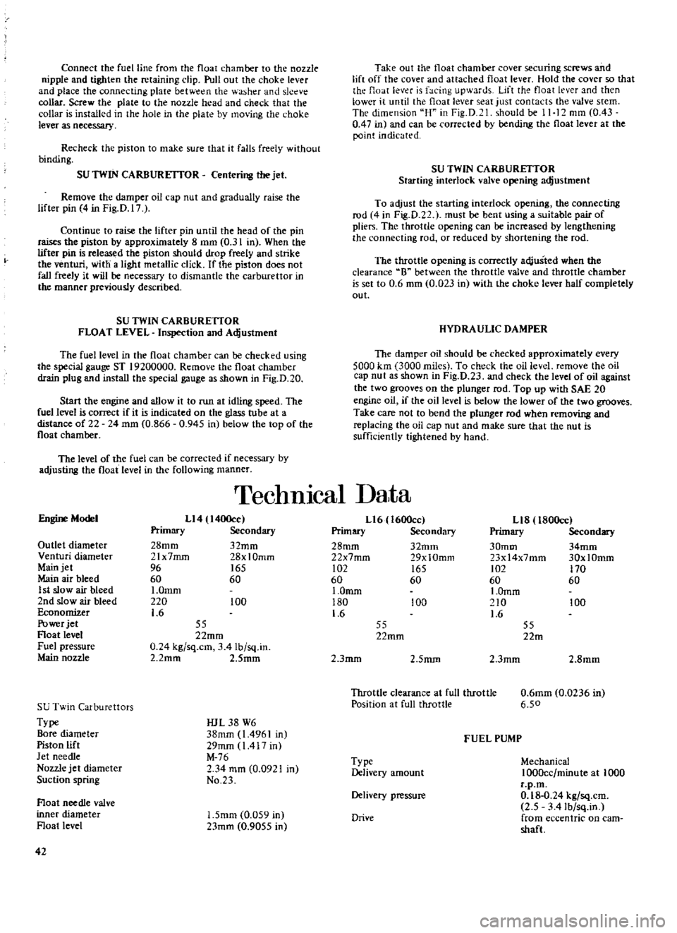
Connect
the
fuel
line
from
the
float
chamber
to
the
nozzle
nipple
and
tighten
the
retaining
clip
Pull
out
the
choke
lever
and
place
the
connecting
plaie
betw
n
the
washer
and
sleeve
collar
Screw
the
plate
to
the
nozzle
head
and
check
that
the
collar
is
installed
in
the
hole
in
the
plate
by
mo
ing
the
choke
lever
as
necessary
Recheck
the
piston
to
make
sure
that
it
falls
freely
without
binding
SU
TWIN
CARBURETTOR
Centering
the
jet
Remove
the
damper
oil
cap
nut
and
gradually
raise
the
lifter
pin
4
in
Fig
D
17
Continue
to
raise
the
lifter
pin
until
the
head
of
the
pin
raises
the
piston
by
approximately
8
mm
0
31
in
When
the
lifter
pin
is
released
the
piston
should
drop
freely
and
strike
the
venturi
with
a
light
metallic
click
If
the
pi
ston
does
not
fall
freely
it
will
be
necessary
to
dismantle
the
carburettor
in
the
manner
previously
described
SU
TWIN
CARBURETTOR
FLOAT
LEVEL
Inspection
and
Adjustment
The
fuel
level
in
the
float
chamber
can
be
checked
using
the
special
gauge
ST
19200000
Remove
the
float
chamber
drain
plug
and
install
the
special
gauge
as
shown
in
Fig
D
20
Start
the
engine
and
allow
it
to
run
at
idling
speed
The
fuel
level
is
conect
if
it
is
indicated
on
the
glass
tu
be
at
a
distance
of
22
24
mm
0
866
0
945
in
below
the
top
of
the
float
chamber
The
level
of
the
fuel
can
be
corrected
if
necessary
by
adjusting
the
float
level
in
the
following
manner
Take
out
the
float
chamber
coveT
securing
screws
and
lift
off
the
cover
and
attached
float
lever
Hold
the
cover
so
that
the
float
lev
r
is
facing
upwards
Lift
the
float
lever
and
then
lower
it
until
the
float
lever
seat
just
contacts
the
valve
stem
The
dimension
uH
in
Fig
D
1
should
be
11
12
mm
0
43
0
47
in
and
can
be
corrected
by
bending
the
float
lever
at
the
point
indicated
SU
TWIN
CARBURETTOR
Starting
interlock
valve
opening
adjustment
To
adjust
the
starting
interlock
opening
the
connecting
rod
4
in
Fig
D
22
1
must
be
bent
using
a
suitable
pair
of
pliers
The
throttle
opening
can
be
increased
by
lengthening
the
connecting
rod
or
reduced
by
shortening
the
rod
The
throttle
opening
is
correctly
adjusted
when
the
clearance
8
between
the
throttle
valve
and
throttle
chamber
is
set
to
0
6
mm
0
023
in
with
the
choke
lever
half
completely
out
HYDRAULIC
DAMPER
The
damper
oil
should
be
checked
approximately
every
5000
km
3000
miles
To
check
the
oil
level
remove
the
oil
cap
nut
as
shown
in
Fig
D
23
and
check
the
level
of
oil
against
the
two
grooves
on
the
plunger
rod
Top
up
with
SAE
20
engine
oil
if
the
oil
level
is
below
the
lower
of
the
two
grooves
Take
care
not
to
bend
the
plunger
rod
when
removing
and
replacing
the
oil
cap
nut
and
make
sure
that
the
nut
is
sufficiently
tightened
by
hand
TechnIcal
Data
Engine
Model
Ll4
I400cc
Primary
Secondary
28mm
32mm
21x7mrn
28xlOmm
96
165
60
60
I
Omm
220
100
1
6
Outlet
diameter
Venturi
diameter
Main
jet
Main
air
bleed
1
st
slow
air
bleed
2nd
slow
air
bleed
Economizer
Power
jet
Float
level
Fuel
pressure
Main
nozzle
55
22mm
0
24
kg
sq
cm
3
41b
sq
in
2
2mm
2
Smm
SU
Twin
Carburettors
Type
Bore
diameter
Piston
lift
Jet
needle
Nozzle
jet
diameter
Suction
spring
IUL
38
W6
38mm
1
4961
in
29mm
1417
in
M
76
2
34
mm
0
0921
in
No
23
Float
needle
valve
inner
diameter
Float
level
1
5mm
0
059
in
23mm
0
9055
in
42
Ll6
1600cc
Primary
Secondary
28mm
32mm
22x7mm
29xlOmm
102
165
60
60
1
0mm
180
100
1
6
Ll8
l80Occ
Primary
Secondary
30mm
34mm
23x14x7mm
30xlOmm
102
170
60
60
I
Omm
210
100
1
6
55
22mm
55
22m
2
3mm
2
5mm
2
3mm
2
8mm
Throttle
clearance
at
full
throttle
Position
at
full
throttle
0
6mm
0
0236
in
6
50
FUEL
PUMP
Type
Delivery
amount
Mechanical
1000cc
minute
at
1000
r
p
m
0
18
0
24
kg
sq
cm
2
5
3
41b
sq
in
from
eccentric
on
cam
shaft
Delivery
pressure
Drive
Page 66 of 171
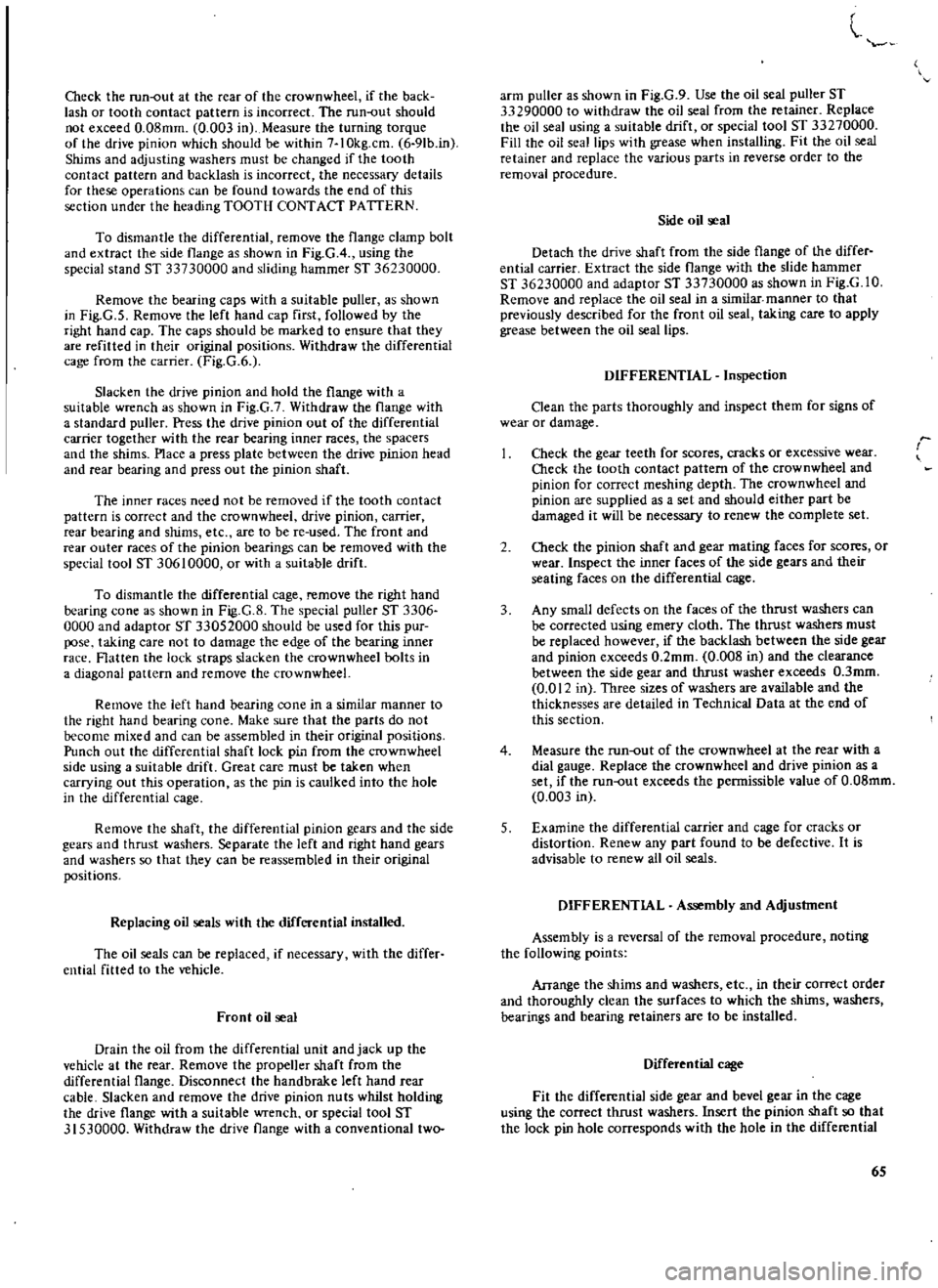
Check
the
run
out
at
the
ceac
of
the
crownwheel
if
the
back
lash
or
tooth
contact
pattern
is
incorrect
The
run
out
should
not
exceed
0
08mm
0
003
in
Measure
the
turning
torque
of
the
drive
pinion
which
should
be
within
7
IOkg
cm
6
9Ib
in
Shims
and
adjusting
washers
must
be
changed
if
the
tooth
contact
pattern
and
backlash
is
incorrect
the
necessary
details
for
these
operations
can
be
found
towacds
the
end
of
this
section
under
the
heading
TOOTH
CONTACT
PATTERN
To
dismantle
the
differential
remove
the
flange
clamp
bolt
and
extract
the
side
flange
as
shown
in
Fig
GA
using
the
special
stand
ST
33730000
and
sliding
hammec
ST
36230000
Remove
the
bearing
caps
with
a
suitable
puller
as
shown
in
Fig
G
5
Remove
the
left
hand
cap
first
followed
by
the
right
hand
cap
The
caps
should
be
marked
to
ensure
that
they
are
refitted
in
their
original
positions
Withdraw
the
differential
cage
from
the
carrier
Fig
G
6
Slacken
the
drive
pinion
and
hold
the
flange
with
a
suitable
wrench
as
shown
in
Fig
G
7
Withdraw
the
flange
with
a
standard
puller
Press
the
drive
pinion
out
of
the
differential
carrier
together
with
the
rear
bearing
inner
races
the
spacers
and
the
shims
Place
a
press
plate
between
the
drive
pinion
head
and
rear
bearing
and
press
out
the
pinion
shaft
The
inner
races
need
not
be
removed
if
the
tooth
contact
pattern
is
correct
and
the
crownwheel
drive
pinion
carrier
rear
bearing
and
shims
etc
are
to
be
re
used
The
front
and
rear
outer
races
of
the
pinion
bearings
can
be
removed
with
the
special
tool
ST
30610000
or
with
a
suitable
drift
To
dismantle
the
differential
cage
remove
the
right
hand
bearing
cone
as
shown
in
Fig
G
8
The
special
puller
ST
3306
0000
and
adaptor
ST
33052000
should
be
used
for
this
pur
pose
taking
care
not
to
damage
the
edge
of
the
bearing
innec
race
Flatten
the
lock
straps
slacken
the
crownwheel
bolts
in
a
diagonal
pattern
and
remove
the
crownwheeL
Remove
the
left
hand
bearing
cone
in
a
similar
manner
to
the
right
hand
bearing
cone
Make
sure
that
the
parts
do
not
become
mixed
and
can
be
assembled
in
their
original
positions
Punch
out
the
differential
shaft
lock
pin
from
the
crownwheel
side
using
a
suitable
drift
Great
care
must
be
taken
when
carrying
out
this
operation
as
the
pin
is
caulked
into
the
hole
in
the
differential
cage
Remove
the
shaft
the
differential
pinion
gears
and
the
side
gears
and
thrust
washers
Separate
the
left
and
right
hand
gears
and
washers
so
that
they
can
be
reassembled
in
their
original
positions
Replacing
oil
seals
with
the
differential
installed
The
oil
seals
can
be
replaced
if
necessary
with
the
differ
ential
fitted
to
the
vehicle
Front
oil
seal
Drain
the
oil
from
the
differential
unit
and
jack
up
the
vehicle
at
the
rear
Remove
the
propeller
shaft
from
the
differential
flange
Disconnect
the
handbrake
left
hand
rear
cable
Slacken
and
remove
the
drive
pinion
nuts
whilst
holding
the
drive
flange
with
a
suitable
wrench
or
special
tool
ST
31530000
Withdraw
the
drive
flange
with
a
conventional
two
l
arm
puller
as
shown
in
Fig
G
9
Use
the
oil
seal
puller
ST
33290000
to
withdraw
the
oil
seal
from
the
retainer
Replace
the
oil
seal
using
a
suitable
drift
or
special
tool
ST
33270000
Fill
the
oil
seal
lips
with
grease
when
installing
Fit
the
oil
seal
retainer
and
replace
the
various
parts
in
reverse
order
to
the
removal
procedure
Side
oil
seal
Detach
the
drive
shaft
from
the
side
flange
of
the
differ
ential
carrier
Extract
the
side
flange
with
the
slide
hammer
ST
36230000
and
adaptor
ST
33730000
as
shown
in
Fig
G
lO
Remove
and
replace
the
oil
seal
in
a
similar
manner
to
that
previously
described
for
the
front
oil
seal
taking
care
to
apply
grease
between
the
oil
seal
lips
DIFFERENTIAL
Inspection
Clean
the
parts
thoroughly
and
inspect
them
for
signs
of
wear
or
damage
Check
the
gear
teeth
for
scores
cracks
or
excessive
wear
Check
the
tooth
contact
pattern
of
the
crownwheel
and
pinion
for
correct
meshing
depth
The
crownwheel
and
pinion
are
supplied
as
a
set
and
should
either
part
be
damaged
it
will
be
necessary
to
renew
the
complete
set
2
Check
the
pinion
shaft
and
gear
mating
faces
for
scores
or
wear
Inspect
the
inner
faces
of
the
side
gears
and
their
seating
faces
on
the
differential
cage
3
Any
small
defects
on
the
faces
of
the
thrust
washers
can
be
corrected
using
emery
cloth
The
thrust
washers
must
be
replaced
however
if
the
backlash
between
the
side
gear
and
pinion
exceeds
0
2mm
0
008
in
and
the
clearance
between
the
side
gear
and
thrust
washer
exceeds
O
3mm
0
012
in
Three
sizes
of
washers
are
available
and
the
thicknesses
are
detailed
in
Technical
Data
at
the
end
of
this
section
4
Measure
the
run
out
of
the
crownwheel
at
the
rear
with
a
dial
gauge
Replace
the
crownwheel
and
drive
pinion
as
a
set
if
the
run
out
exceeds
the
permissible
value
of
O
08mm
0
003
in
5
Examine
the
differential
carrier
and
cage
for
cracks
or
distortion
Renew
any
part
found
to
be
defective
It
is
advisable
to
renew
all
oil
seals
DIFFERENTIAL
Assembly
and
Adjustment
Assembly
is
a
reversal
of
the
removal
procedure
noting
the
following
points
Arrange
the
shims
and
washers
etc
in
their
correct
order
and
thoroughly
clean
the
surfaces
to
which
the
shims
washers
bearings
and
bearing
retainecs
are
to
be
installed
Differential
cage
Fit
the
differential
side
gear
and
bevel
gear
in
the
cage
using
the
correct
thrust
washers
Insert
the
pinion
shaft
so
that
the
lock
pin
hole
corresponds
with
the
hole
in
the
differential
65
Page 80 of 171
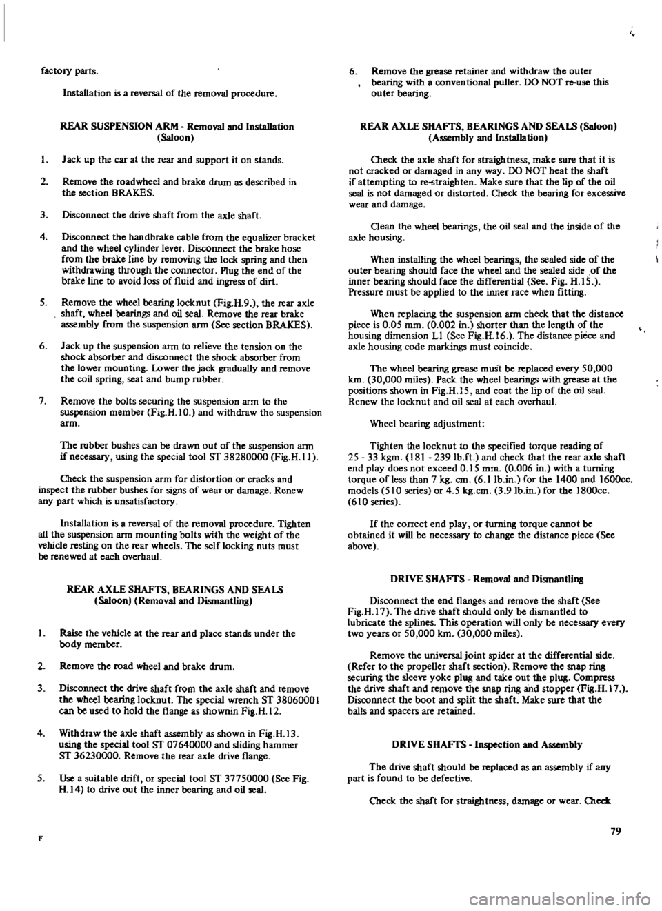
factory
parts
Installation
is
a
reversal
of
the
removal
procedure
REAR
SUSPENSION
ARM
Removal
and
Installation
Saloon
I
J
ad
up
the
car
at
the
rear
and
support
it
on
stands
2
Remove
the
road
wheel
and
brake
drum
as
described
in
the
section
BRAKES
3
Disconnect
the
drive
shaft
from
the
axle
shaft
4
Disconnect
the
handbrake
cable
from
the
equalizer
bracket
and
the
wheel
cylinder
lever
Disconnect
the
brake
hose
from
the
brake
line
by
removing
the
lock
spring
and
then
withdrawing
through
the
connector
Plug
the
end
of
the
brake
line
to
avoid
loss
of
fluid
and
ingress
of
dirt
5
Remove
the
wheel
bearing
locknut
Fig
H
9
the
rear
axle
shaft
wheel
bearings
and
oil
seal
Remove
the
rear
brake
assembly
from
the
suspension
ann
See
section
BRAKES
6
Jack
up
the
suspension
arm
to
relieve
the
tension
on
the
shock
absorber
and
disconnect
the
shock
absorber
from
the
lower
mounting
Lower
the
jack
gradually
and
remove
the
coil
spring
seat
and
bump
rubber
7
Remove
the
bolts
securing
the
suspension
arm
to
the
suspension
member
Fig
H
IO
and
withdraw
the
suspension
arm
The
rubber
bushes
can
be
drawn
out
of
the
suspension
arm
if
necessary
using
the
special
tool
ST
38280000
Fig
H
Il
O1eck
the
suspension
arm
for
distortion
or
cracks
and
inspect
the
rubber
bushes
for
signs
of
wear
or
damage
Renew
any
part
which
is
unsatisfactory
Installation
is
a
reversal
of
the
removal
procedure
Tighten
all
the
suspension
arm
mounting
bolts
with
the
weight
of
the
vehicle
resting
on
the
rear
wheels
The
self
locking
nuts
must
be
renewed
at
each
overhaul
REAR
AXLE
SHAFTS
BEARINGS
AND
SEALS
Saloon
Removal
and
Dismantling
I
Raise
the
vehicle
at
the
rear
and
place
stands
under
the
body
member
2
Remove
the
road
wheel
and
brake
drum
3
Disconnect
the
drive
shaft
from
the
axle
shaft
and
remove
the
wheel
bearing
locknut
The
special
wrench
ST
38060001
can
be
used
to
hold
the
flange
as
shownin
Fig
H
12
4
Withdraw
the
axle
shaft
assembly
as
shown
in
Fig
H
13
using
the
special
tool
ST
07640000
and
sliding
hammer
ST
36230000
Remove
the
rear
axle
drive
flange
5
Use
a
suitable
drift
or
special
tool
ST
37750000
See
Fig
H
14
to
drive
out
the
inner
bearing
and
oil
seal
F
6
Remove
the
grease
retainer
and
withdraw
the
outer
bearing
with
a
conventional
puller
DO
NOT
re
use
this
outer
bearing
REAR
AXLE
SHAFTS
BEARINGS
AND
SEALS
Saloon
Assembly
and
Installation
Oleck
the
axle
shaft
for
straightness
make
sure
that
it
is
not
cracked
or
damaged
in
any
way
00
NOT
heat
the
shaft
if
attempting
to
re
straighten
Make
sure
that
the
lip
of
the
oil
seal
is
not
damaged
or
distorted
Check
the
bearing
for
excessive
wear
and
damage
Oean
the
wheel
bearings
the
oil
seal
and
the
inside
of
the
axle
housing
When
installing
the
wheel
bearings
the
sealed
side
of
the
outer
bearing
should
face
the
wheel
and
the
sealed
side
of
the
inner
bearing
should
face
the
differential
See
Fig
H
IS
Pressure
must
be
applied
to
the
inner
race
when
fitting
When
replacing
the
suspension
arm
check
that
the
distance
piece
is
0
05
mm
0
002
in
shorter
than
the
length
of
the
housing
dimension
LI
See
Fig
H
16
The
distance
piece
and
axle
housing
code
markings
must
coincide
The
wheel
bearing
grease
must
be
replaced
every
50
000
km
30
000
miles
Pack
the
wheel
bearings
with
grease
at
the
positions
shown
in
Fig
H
IS
and
coat
the
lip
of
the
oil
seal
Renew
the
locknut
and
oil
seal
at
each
overhaul
Wheel
bearing
adjustment
Tighten
the
locknut
to
the
specified
torque
reading
of
25
33
kgm
181
239
lb
ft
and
check
that
the
rear
axle
shaft
end
play
does
not
exceed
0
15
mm
0
006
in
with
a
turning
torque
of
less
than
7
kg
em
6
11b
in
for
the
1400
and
1600cc
models
510
series
or
4
5
kg
em
3
91b
in
for
the
1800cc
610
series
If
the
correct
end
play
or
turning
torque
cannot
be
obtained
it
will
be
necessary
to
change
the
distance
piece
See
above
DRIVE
SHAFTS
Removal
and
Dismantlill8
Disconnect
the
end
flanges
and
remove
the
shaft
See
Fig
H
17
The
drive
shaft
should
only
be
dismantled
to
lubricate
the
splines
This
operation
will
only
be
necessary
every
two
years
or
50
000
km
30
000
miles
Remove
the
universal
joint
spider
at
the
differential
side
Refer
to
the
propeller
shaft
section
Remove
the
snap
ring
securiilg
the
sleeve
yoke
plug
and
take
out
the
plug
Compress
the
drive
shaft
and
remove
the
snap
ring
and
stopper
Fig
H
17
Disconnect
the
boot
and
split
the
shaft
Make
sure
that
the
balls
and
spacers
are
retained
DRIVE
SHAFTS
Inspection
and
Assembly
The
drive
shaft
should
be
replaced
as
an
assembly
if
any
part
is
found
to
be
defective
Check
the
shaft
for
straightness
damage
or
wear
Old
79
Page 150 of 171
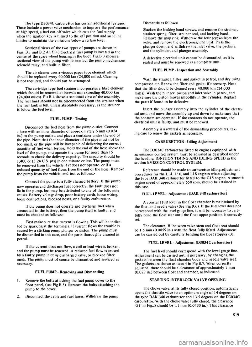
The
type
D3034C
carburettor
has
certain
additional
features
These
include
a
power
valve
mechanism
to
improve
the
performance
at
high
speed
a
fuel
cut
off
valve
which
cuts
the
fuel
supply
when
the
ignition
key
is
turned
to
the
off
position
and
an
idling
limiter
to
maintain
the
emissions
below
a
certain
level
Sectional
views
of
the
two
types
of
pumps
are
shown
in
Figs
8
1
and
B
2
An
EP
3
electrical
fuel
pump
is
located
in
the
centre
of
the
spare
wheel
housing
in
the
boot
Fig
B
3
shows
a
sectional
view
of
the
pump
with
its
contact
the
pump
mechanisms
solenoid
relay
and
built
in
filter
The
air
cleaner
uses
a
viscous
paper
type
element
which
should
be
replaced
every
40
000
km
24
000
miles
Cleaning
is
not
required
and
should
not
be
attempted
The
cartridge
type
fuel
strainer
incorporates
a
fibre
clement
which
should
be
renewed
at
inervals
not
exceeding
40
000
km
24
000
miles
Fit
B
4
shows
a
sectional
view
of
the
assembly
The
fuel
lines
should
not
be
disconnected
from
the
strainer
when
the
fuel
tank
is
full
unless
absolutely
necessary
as
the
strainer
is
below
the
fuel
level
FUEL
PUMP
Testing
Disconnect
the
fuel
hose
from
the
pump
outlet
Connect
a
hose
with
an
inner
diameter
of
approximately
6
mm
0
024
in
to
the
pump
outlet
and
place
a
container
under
the
end
of
the
pipe
Note
that
the
inner
diameter
of
the
pipe
must
not
be
too
small
or
the
pipe
will
be
incapable
of
delivering
the
correct
quantity
of
fuel
when
testing
Hold
the
end
of
the
hose
above
the
level
of
the
pump
and
operate
the
pump
for
more
than
IS
seconds
to
check
the
delivery
capacity
The
capacity
should
be
I
400
cc
3
24
U
S
pts
in
one
minute
or
less
The
pump
must
be
removed
from
the
vehicle
if
it
does
not
operate
or
if
a
reduced
quantity
of
fuel
flows
from
the
end
of
the
hose
Remove
the
pump
from
the
vehicle
and
test
as
follows
Connect
the
pump
to
a
fully
charged
battery
If
the
pump
now
operates
and
discharges
fuel
correctly
the
fault
does
not
lie
in
the
pump
but
may
be
attributed
to
any
of
the
following
causes
Battery
voltage
drop
poor
battery
earth
loose
wiring
loose
connections
blocked
hoses
or
a
faulty
carburettor
If
the
pump
does
not
operate
and
discharge
fuel
when
connected
to
the
battery
then
the
pump
itself
is
faulty
and
must
be
checked
as
follows
First
make
sure
that
current
is
flowing
This
will
be
indica
ted
by
sparking
at
the
tenninals
If
current
flows
the
trouble
is
caused
by
a
sticking
pump
plunger
or
piston
The
pump
must
be
dismantled
in
this
case
and
the
parts
thoroughly
cleaned
in
petrol
If
the
current
does
not
flow
a
coil
or
lead
wire
is
broken
and
the
pump
must
be
renewed
A
reduced
fuel
flow
is
caused
by
a
faulty
pump
inlet
or
discharged
valve
or
blocked
filter
mesh
The
pump
must
of
course
be
dismantled
and
serviced
as
necessary
FUEL
PUMP
Removing
and
Dismantling
Remove
the
bolts
attaching
the
fuel
pump
cover
to
the
floor
panel
see
Fig
B
S
Remove
the
bolts
attaching
the
pump
to
the
cover
2
Disconnect
the
cable
and
fuel
hoses
Withdraw
the
pump
Dismantle
as
follows
Slacken
the
locking
band
screws
and
remove
the
strainer
strainer
spring
filter
strainer
seal
and
locking
band
Remove
the
snap
ring
Withdraw
the
four
screws
from
the
yoke
and
remove
the
electromagnetic
ulJ
it
Press
the
plunger
down
and
withdraw
the
inlet
vaive
the
packing
and
the
cylinder
and
plunger
assembly
A
defective
eledrical
unit
cannot
be
dismantled
as
it
is
sealed
and
must
be
renewed
as
a
complete
unit
FUEL
PUMP
Inspection
and
Assembly
Wash
the
strainer
filter
and
gasket
in
petrol
and
dry
using
compressed
air
Renew
the
filter
and
gasket
if
necessary
Note
that
the
filter
should
be
cleaned
every
40
000
km
24
000
miles
Wash
the
plunger
piston
and
inlet
valve
in
petrol
and
make
sure
the
piston
moves
smoothly
in
the
cylinder
Replace
the
parts
if
found
to
be
defective
Insert
the
plunger
assembly
into
the
cylinder
of
the
electri
cal
unit
and
move
the
assembly
up
and
down
to
make
sure
tha
t
the
contacts
are
operated
If
the
contacts
do
not
operate
the
electrical
unit
is
faulty
and
must
be
renewed
Assembly
is
a
reversal
of
the
dismantling
procedures
tak
ing
care
to
renew
the
gaskets
as
necessary
CARBURETIOR
Idling
Adjustment
The
D3034C
carburettor
fitted
to
engines
equipped
with
an
emission
control
system
must
be
adjusted
as
described
under
the
heading
IGNITION
TIMING
AND
IDLING
SPEED
in
the
section
EMISSION
CONTROL
SYSTEM
Reference
should
be
made
to
carburettor
idling
adjustment
procedures
for
the
L14
L16
and
LI8
engines
when
adjusting
the
type
DAK
340
carburettor
fitted
to
the
G
18
engine
A
smooth
engine
speed
of
approximately
550
rpm
should
be
attained
in
this
case
FUEL
lEVEL
Adjustment
DAK
340earburettor
A
constant
fuellevcl
in
the
float
chamber
is
maintained
by
the
float
and
needle
valve
See
Fig
8
6
If
the
fuel
level
does
not
correspond
with
the
level
gauge
line
it
will
be
necessary
to
care
fully
bend
the
float
seat
until
the
float
upper
position
is
correctly
set
The
clearance
H
between
valve
stem
and
float
seat
should
be
I
5
mm
0
0059
in
with
the
float
fully
lifted
Adjustment
can
be
carried
out
by
carefully
bending
the
float
stopper
3
FUEL
lEVEL
Adjustment
D3034Ccarburettnr
The
fuel
level
should
correspond
with
the
level
gauge
line
Adjustment
can
be
carried
out
if
necessary
by
changing
the
gaskets
between
the
float
chamber
body
and
needle
valve
seat
The
gaskets
are
shown
as
item
4
in
Fig
B
7
When
correctly
adjusted
there
should
be
a
clearance
of
approximately
7
mm
0
027
in
between
float
and
chamber
as
indicated
STARTING
INTERLOCK
VALVE
OPENING
The
choke
valve
at
its
fully
closed
position
automatically
opens
the
throttle
valve
to
an
optimum
angle
of
14
degrees
on
the
type
DAK
340
carburettor
and
13
5
degrees
on
the
D3034C
carburettor
With
the
choke
valve
fully
closed
the
clearance
G
I
in
Fig
8
should
be
1
I
mm
0
0433
in
This
clearance
S19
Page 152 of 171
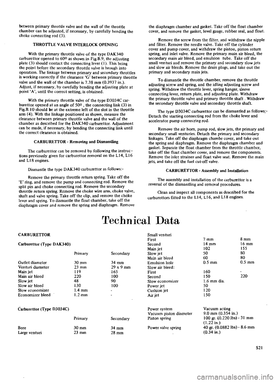
between
primary
throttle
valve
and
the
wall
of
the
throttle
chamber
can
be
adjusted
if
necessary
by
carefully
bending
the
choke
connecting
rod
3
THROTILE
VALVE
INTERLOCK
OPENING
With
the
primary
throttle
valve
of
the
type
DAK340
carburettor
opened
to
600
as
shown
in
Fig
B
9
the
adjusting
plate
3
should
contact
the
connecting
lever
J
This
being
the
point
before
the
secondary
throttle
valve
is
brough
into
operation
The
linkage
between
primary
and
secondary
throttles
is
working
correctly
if
the
clearance
G
between
primary
throttle
valve
and
the
wall
of
the
chamber
is
738
mm
0
3937
in
Adjust
if
necessary
by
carefully
bending
the
adjusting
plate
at
point
A
until
the
correct
setting
is
obtained
With
the
primary
throttle
valve
of
the
type
D3034C
car
burettor
opened
at
an
angle
of
500
the
connecting
link
3
in
Fig
B
IO
should
ge
at
the
extreme
left
of
the
slot
in
the
throttle
ann
4
With
the
linkage
positioned
as
shown
measure
the
clearance
between
primary
throttle
valve
and
the
wall
of
the
chamber
as
described
for
the
DAK340
carburettor
Adjustment
can
be
made
if
necessary
by
bending
the
connecting
link
until
the
correct
clearance
is
obtained
CARBURElTOR
Removing
and
Dismantling
The
carburettor
can
be
removed
by
following
the
instruc
tions
previously
given
for
carburettor
removal
on
the
Ll4
L16
and
LIB
engines
Dismantle
the
type
DAK340
carburettor
as
follows
Remove
the
primary
throttle
return
spring
Take
off
the
E
ring
and
remove
the
pump
and
connecting
rod
Remove
the
split
pin
and
choke
connecting
rod
Remove
the
secondary
throttle
return
spring
Remove
the
choke
wire
arm
choke
valve
shaft
and
valve
spring
Take
off
the
clip
and
remove
the
choke
lever
and
spring
To
dismantle
the
float
chamber
take
off
the
diaphragm
cover
and
remove
the
spring
and
diaphragm
Remove
the
diaphragm
chamber
and
gasket
Take
off
the
float
chamber
cover
and
remove
the
gasket
level
gauge
rubber
seal
and
float
Remove
the
screw
from
the
filter
and
withdraw
the
nipple
and
filter
Remove
the
needle
valve
Take
off
the
cylinder
cover
and
pump
cover
and
withdraw
the
piston
piston
return
spring
and
inlet
valve
Remove
the
primary
main
air
bleed
the
secondary
main
air
bleed
and
emulsion
tube
Take
off
the
small
venturi
and
remove
the
primary
and
secondary
slow
jets
and
slow
air
bleeds
Remove
the
drain
plugs
and
take
out
the
primary
and
secondary
main
jets
To
dismantle
the
throttle
chamber
remove
the
throttle
adjusting
screw
and
spring
and
the
idling
adjusting
screw
and
spring
Withdraw
the
throttle
lever
spring
hanger
sleeve
connecting
lever
return
plate
and
adjusting
plate
Withdraw
the
primary
throttle
valve
and
primary
throttle
shaft
Withdraw
the
secondary
throttle
valve
and
secondary
throttle
shaft
The
type
D3034C
carburettor
can
be
dismantled
as
follows
Detach
the
starting
connecting
rod
from
the
choke
lever
and
accelerator
pump
connecting
rod
Remove
the
air
horn
pump
rod
slow
jets
the
primary
and
secondary
small
venturies
Detach
the
primary
and
secondary
linkages
Take
off
the
diaphragm
chambe
cover
and
take
out
the
spring
and
diaphragm
Remove
the
diaphragm
chamber
and
gasket
Separate
the
float
chamber
from
the
throttle
chamber
take
off
the
float
chamber
cover
and
remove
the
components
Remove
the
inlet
strainer
and
float
valve
seat
Remove
the
main
jets
and
take
off
the
fuel
cut
off
valve
CARBURETTOR
Assembly
and
Installation
The
assembly
and
installation
of
the
carburettor
is
a
reversal
of
the
dismantling
and
removal
procedures
Clean
and
inspect
all
components
as
described
for
the
carburettors
fitted
to
the
Ll4
Ll6
and
LI8
engines
TechnIcal
Data
CARBURETIOR
Small
ven
turi
First
7mm
8mm
Carburettor
Type
DAK340
Second
14mm
16mm
Main
jet
02
155
Primary
Secondary
Slow
jet
50
80
Main
air
bleed
60
80
Outlet
diameter
30mm
34mm
Emulsion
hole
0
5
mm
O
5mm
Venturi
diameter
23
mm
29
x
9
mm
Slow
air
bleed
Main
jet
119
165
First
160
Main
air
bleed
220
100
Second
150
220
Slow
jet
48
90
Slow
economizer
1
6
mm
dia
Slow
air
bleed
130
100
Power
jet
50
Slow
economizer
L4mm
Cushion
jet
120
Economizer
bleed
1
2mm
Air
jet
150
Carburettor
Type
D3034C
Power
system
Vacllum
acting
Vacuum
piston
diameter
9
0
mm
0
354
in
Primary
Secondary
Piston
spring
100
gr
0
220
Ibs
31
mm
1
22
in
Bore
30mm
34mm
Power
valve
spring
40
gr
0
0882
lbs
8
6mm
Large
venturi
23mm
28mm
0
34
in
52