weight DATSUN 610 1969 Workshop Manual
[x] Cancel search | Manufacturer: DATSUN, Model Year: 1969, Model line: 610, Model: DATSUN 610 1969Pages: 171, PDF Size: 10.63 MB
Page 5 of 171
t
r
Engine
type
Ovendi
cngth
1300
L
13
Overall
width
Oyerall
height
Turning
circle
din
metres
tfeet
Supen
eded
by
Track
font
rear
1400
c
c
car
Ground
dearance
Olin
Weight
dry
I
820
808
I
Fuel
tClflk
capacity
35
29
6
150
93
Fuel
consumption
aximum
peed
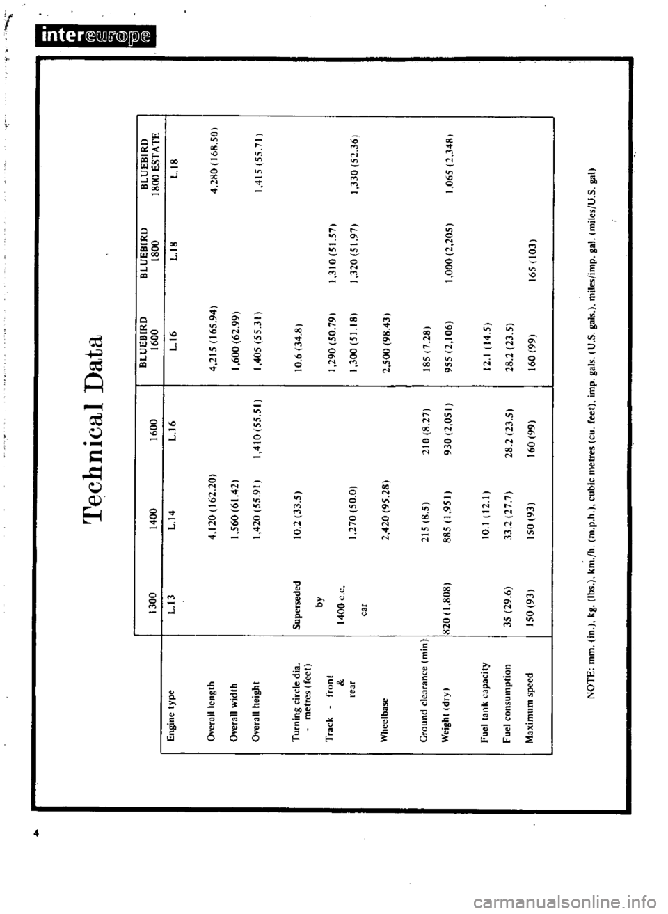
Technical
Data
BLUEBIRD
400
1600
1600
U4
U6
0
4
120
162
20
1
560
6142
410
55
51
420
55
91
10
2
33
5
270
50
0
2
420
95
281
215
8
5
885
1
950
210
8
27
930
2
050
10
1
12
33
2
27
7
50
931
28
2123
5
60
99
L
16
4
215
165
941
1
600
62
99
405
55
3
Ii
0
6
34
8
290
50
79
1
300
51
18
2
500
98
43
185
7
281
955
2
1061
12
14
5
28
2
23
5
60
991
BLUEBIRD
1800
L
18
3
0
5
57
320
5
971
000
2
2051
165
103
BLUEBIRD
1800
ESTATE
U8
4
280
168
501
4
5
557
330
52
361
1
065
2
348
Page 14 of 171
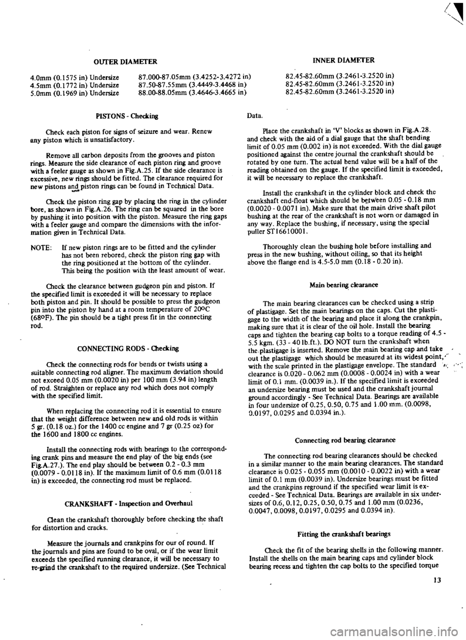
OUTER
DIAMETER
4
0mm
0
1575
in
Undersize
4
5mm
0
1772
in
Undersize
5
Omm
0
1969
in
Undersize
87
000
87
05mm
3
4252
3
4272
in
87
50
87
55mm
3
4449
3
4468
in
88
00
88
05mm
3
4646
3
4665
in
PISTONS
Checking
Check
each
piston
for
signs
of
seizure
and
wear
Renew
BIlY
piston
which
is
unsatisfactory
Remove
all
carbon
deposits
from
the
grooves
and
piston
rings
Measure
the
side
clearance
of
each
piston
ring
and
groove
with
a
feeler
gauge
as
shown
in
Fig
A
25
If
the
side
clearance
is
excessive
new
rings
should
be
fitted
The
clearance
required
for
new
pistons
a
piston
rings
can
be
found
in
Technical
Data
Check
the
piston
ring
gap
by
placing
the
ring
in
the
cylinder
bore
as
shown
in
Fig
A
26
The
ring
can
be
squared
in
the
bore
by
pushing
it
into
position
with
the
piston
Measure
the
ring
gaps
with
a
feeler
gauge
and
compare
the
dimensions
with
the
infor
mation
given
in
Technical
Data
NOTE
If
new
piston
rings
are
to
be
fitted
and
the
cylinder
has
not
been
rebafed
check
the
piston
ring
gap
with
the
ring
positioned
at
the
bottom
of
the
cylinder
This
being
the
position
with
the
least
amount
of
wear
O1eck
the
clearance
between
gudgeon
pin
and
piston
If
the
specified
limit
is
exceeded
it
will
be
necessary
to
replace
both
piston
and
pin
It
should
be
possible
to
press
the
gudgeon
pin
into
the
piston
by
hand
at
a
room
temperature
of
200C
680F
The
pin
should
be
a
tight
press
fit
in
the
connecting
rod
CONNECTING
RODS
O1ecking
Cleck
the
connecting
rods
for
bends
or
twists
using
a
guitable
connecting
rod
aligner
The
maximum
deviation
should
not
exceed
0
05
mm
0
0020
in
per
100
mm
3
94
in
length
of
rod
Straighten
or
replace
any
rod
which
does
not
comply
with
the
specified
limit
When
replacing
the
connecting
rod
it
is
essential
to
ensure
that
the
weight
difference
between
new
and
old
rods
is
within
5
gr
0
18
oz
for
the
1400
cc
engine
and
7
gr
0
25
oz
for
the
1600
and
1800
cc
engines
Install
the
connecting
rods
with
bearings
to
the
correspond
ing
crank
pins
and
measure
the
end
play
of
the
big
ends
s
e
Fig
A
27
The
end
play
should
be
between
0
2
0
3
mm
0
0079
0
0118
in
fthe
maximum
limit
of
0
6
mm
0
Ql18
in
is
exceeded
the
connecting
rod
must
be
replaced
CRANKSHAFT
Inspection
and
Overhaul
aean
the
crankshaft
thoroughly
before
checking
the
shaft
for
distortion
and
cracks
Measure
the
journals
and
crankpins
for
our
of
round
If
the
journals
and
pins
are
found
to
be
oval
or
if
the
wear
limit
exceeds
the
specified
fUnning
clearance
it
will
be
necessary
to
re
llrind
the
crankshaft
to
the
required
undersize
See
Technical
I
INNER
DIAMETER
82
45
82
60mm
3
24613
2520
in
82
4S
82
60mm
3
24613
2520
in
82
4S
82
60mm
3
24613
2520
in
Data
Place
the
crankshaft
in
V
blocks
as
shown
in
Fig
A
28
and
check
with
the
aid
of
a
dial
gauge
that
the
shaft
bending
limit
of
0
05
mm
0
002
in
is
not
exceeded
With
the
dial
gauge
positioned
against
the
centre
journal
the
crankshaft
should
be
rotated
by
one
turn
The
actual
bend
value
will
be
a
half
of
the
reading
obtained
on
the
gauge
If
the
specified
limit
is
exceeded
it
will
be
necessary
to
replace
the
crankshaft
Install
the
crankshaft
in
the
cylinder
block
and
check
the
crankshaft
end
float
which
should
be
be
J
Yieen
0
05
0
18
mm
0
0020
0
0071
in
Make
sure
that
the
main
drive
shaft
pilot
bushing
at
the
rear
of
the
crankshaft
is
not
worn
or
damaged
in
any
way
Replace
the
bushing
if
necessary
using
the
special
puller
STl
66
1000
I
Thoroughly
clean
the
bushing
hole
before
installing
and
press
in
the
new
bushing
without
oiling
so
that
its
height
above
the
flange
end
is
4
5
5
0
mm
0
18
0
20
in
Main
bearing
clearance
The
main
bearing
clearances
can
be
checked
using
a
strip
of
plastigage
Set
the
main
bearings
on
the
caps
Cut
the
plasti
gage
to
the
width
of
the
bearing
and
place
it
along
the
crankpin
making
sure
that
it
is
clear
of
the
oil
hole
Install
the
bearing
caps
and
tighten
the
bearing
cap
bolts
to
a
torque
reading
of
4
5
5
5
kgm
33
40
Ib
ft
DO
NOT
turn
the
crankshaft
when
the
plastigage
is
inserted
Remove
the
main
bearing
cap
and
take
out
the
plastigage
which
should
be
measured
at
its
widest
po
t
with
the
scale
printed
in
the
plastigage
envelope
The
standard
clearance
is
0
020
0
062
mm
0
0008
0
0024
in
with
a
wear
limit
of
0
1
mm
0
0039
in
If
the
specified
limit
is
exceeded
an
undersize
bearing
must
be
used
and
the
crankshaft
journal
ground
accordingly
See
Technical
Data
Bearings
are
available
in
four
undersize
of
0
25
0
50
0
75
and
1
00
mm
0
0098
0
0197
0
0295
and
0
0394
in
Connecting
rod
bearing
clearance
The
connecting
rod
bearing
clearances
should
be
checked
in
a
similar
manner
to
the
main
bearing
clearances
The
standard
clearance
is
0
025
0
055
mm
0
0010
0
0022
in
with
a
wear
limit
of
0
1
mm
0
0039
in
Undersize
bearings
must
be
fitted
and
the
crankpins
reground
if
the
specified
wear
limit
is
ex
ceeded
See
Technical
Data
Bearings
are
available
in
six
under
sizes
of
0
6
0
12
0
25
0
50
0
75
and
1
00
mm
0
0236
0
0047
0
0098
0
0197
0
0295
and
0
0394
in
Fitting
the
crankshaft
bearings
Cb
eck
the
fit
of
the
bearing
shells
in
the
following
manner
Install
the
shells
on
the
main
bearing
caps
and
cylinder
block
bearing
recess
and
tighten
the
cap
bolts
to
the
specified
torque
13
Page 15 of 171

inter
Q1I
f
Q
I
ll
oJ
Fig
A
27
Olecking
the
big
end
play
Fig
A
28
Checking
the
crankshaft
for
run
out
Weight
Fig
A
29
Checking
the
bearing
crush
Fig
A
30
Checking
the
camshaft
sprocket
for
run
out
Fig
A
31
OIecking
the
camshaft
end
float
Fig
A
32
Installing
he
valves
14
Page 22 of 171
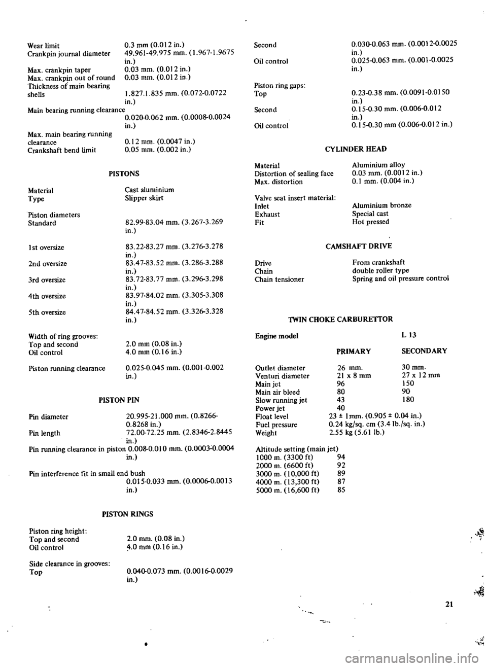
Wear
limit
Crank
pin
journal
diameter
Max
crankpin
taper
Max
crankpin
out
of
round
Thickness
of
main
bearing
shells
0
3
mm
0
012
in
49
961
49
975
mm
1
967
1
9675
in
0
03
mm
0
012
in
0
03
mm
0
012
in
1
827
1
835
mm
0
072
0
0722
in
Main
bearing
running
clearance
0
020
0
062
mm
0
0008
0
0024
in
Max
main
bearing
running
clearance
Crankshaft
bend
limit
Material
Type
Piston
diameters
Standard
I
st
oversize
2nd
oversize
3rd
oversize
4th
oversize
5th
oversize
Width
of
ring
grooves
Top
and
second
Oil
control
Piston
running
clearance
0
12
mm
0
0047
in
0
05
mm
0
002
in
PISTONS
Cast
aluminium
Slipper
skirt
82
99
83
04
mm
3
267
3
269
in
83
22
83
27
mm
3
276
3
278
in
83
47
83
52
mm
3
286
3
288
in
83
72
83
77
mm
3
296
3
298
in
83
97
84
02
mm
3
305
3
308
in
84
47
84
52
mm
3
326
3
328
in
2
0
mm
0
08
in
4
0
mm
0
16
in
0
025
0
045
mm
0
001
0
002
in
PISTON
PIN
Pin
diameter
20
995
21
000
mm
0
8266
0
8268
in
Pin
length
72
00
72
25
mm
2
8346
2
8445
in
Pin
running
clearance
in
piston
0
008
0
010
mm
0
0003
0
0004
in
Pin
interference
fit
in
small
end
bush
0
015
0
033
mm
0
0006
0
0013
in
Piston
ring
height
Top
and
second
Oil
control
Side
clearance
in
grooves
Top
PISTON
RINGS
2
0
mm
0
08
in
4
0
mm
0
16
in
0
040
0
073
mm
0
0016
0
0029
in
Second
Oil
control
Piston
ring
gaps
Top
Second
Oil
control
Material
Distortion
of
sealing
face
Max
distortion
Valve
seat
insert
material
Inlet
Exhaust
Fit
Drive
Chain
Chain
tensioner
0
030
0
063
mm
0
0012
0
0025
in
0
025
0
063
mm
0
001
0
0025
in
0
23
0
38
mm
0
0091
0
0150
in
0
15
0
30
mm
0
006
0
012
in
0
15
0
30
mm
0
006
0
012
in
CYLINDER
HEAD
Aluminium
alloy
0
03
mm
0
0012
in
0
1
mm
0
004
in
Aluminium
bronze
Special
cast
Hot
pressed
CAMSHAFT
DRIVE
From
crankshaft
double
roller
type
Spring
and
oil
pressure
control
Engine
model
lWIN
CHOKE
CARBURE
ITOR
Outlet
diameter
Venturi
diameter
Main
jet
Main
air
bleed
Slow
running
jet
Power
jet
Float
level
Fuel
pressure
Weight
Altitude
setting
main
jet
1000
m
3300
ft
94
2000
m
6600
ft
92
3000
m
10
000
ft
89
4000
m
13
300
ft
87
5000
m
16
600
ft
85
PRIMARY
L13
SECONDARY
30mm
27x
12mm
150
90
180
26
mm
21
x
8
mm
96
80
43
40
23
I
mm
0
905
0
04
in
0
24
kg
sq
em
3
41b
sq
in
2
55
kg
5
61
lb
1
21
Page 29 of 171

inter
lW
j
@lPX
TT
Y
Gw
PRIMARY
COIL
RESISTOR
I
I
l1@
l
I
IGNITION
U
SECONDARY
COIL
COIL
IS
AK
R
POIN
i
1
1
DISTRISUTOR
I
1
J
ISI
V
nl
N
I
TO
STARTER
l
1
ROTOR
HEAD
r
SPARK
PLUG
Fig
C
t
Ignition
sys
em
circuit
diagram
i
II
@
1
1
@
J
i
9
28
l
I
i
1
I
I
@
@
G
N
7
Fig
C
2lgnition
distributor
1
Shaft
assembly
2
Collar
assembly
3
Cam
assembly
4
Governor
weights
5
Governor
spring
6
Rowr
head
7
Breaker
plate
8
Contact
set
9
Tennirtal
assembly
10
Vacuum
control
J
1
Condenser
12
Distributor
cap
13
Carbon
point
14
Plate
15
CIilmp
Page 30 of 171
IgnItIon
System
DESCRII
TION
IGNITION
TIMING
IGNITION
DISTRIBUTOR
Maintenance
ADJUSTING
THE
CONTACT
BREAKER
GAP
CENTRIFUGAL
ADVANCE
MECHANISM
VACUUM
ADVANCE
MECHANISM
IGNITION
DISTRIBUTOR
Removal
and
Dismantling
IGNITION
DISTRIBUTOR
Assembling
and
Installation
SPARKING
PLUGS
DESCRII
TION
The
ignition
circuit
comprises
the
distributor
ignition
coil
ignition
switch
spark
plugs
high
tension
lead
and
the
battery
See
Fig
C
1
The
Hitachi
distributor
is
shown
in
exploded
form
in
Fig
C
2
19niton
timing
is
automatically
regulated
by
the
distributor
centrifugal
advance
mechanism
or
vacuum
advance
mechanism
depending
upon
the
demand
made
on
the
engine
The
vacuum
advance
mechanism
operates
under
part
throttle
only
and
uses
intake
manifold
depression
to
advance
the
ignition
timing
When
the
engine
speed
is
increased
the
vacuum
is
inoperative
and
ignition
timing
is
regulated
by
the
centrifugal
advance
mechanism
The
centrifugal
advance
mechanism
uses
a
system
of
governor
weights
and
springs
which
turn
the
carn
assembly
in
on
anti
clockwise
direction
to
advance
the
ignition
timing
As
the
engine
speed
is
decreased
the
weights
move
back
and
allow
the
cam
to
return
thereby
retarding
the
ignition
timing
The
ignition
coil
is
an
oil
filled
unit
comprising
a
coil
around
which
is
wound
the
secondary
and
primary
windings
The
number
of
turns
in
the
primary
winding
provide
a
high
secondary
voltage
throughout
the
speed
range
The
resistor
is
automatically
by
passed
at
the
moment
of
starting
and
allows
the
ignition
coil
to
be
directly
connected
to
the
battery
This
applies
the
full
battery
voltage
to
the
coil
to
give
the
necessary
staTting
boost
When
the
starter
switch
is
released
the
current
flows
through
the
resistor
and
the
voltage
through
the
coil
is
dropped
for
normal
running
purposes
IGNITION
TIMING
The
ignition
timing
can
be
accurately
checked
using
a
stroboscopic
timing
light
which
should
be
connected
in
accor
dance
with
the
manufacturers
instructions
Make
sure
that
the
timing
marks
on
the
crankshaft
pulley
are
visible
if
they
are
not
visible
mark
them
with
chalk
or
white
paint
Each
mark
represents
a
50
division
of
the
crank
angle
Disconnect
the
distributor
vacuum
line
start
the
engine
and
allow
it
to
run
at
normal
idling
speed
or
slightly
below
Point
the
timing
light
at
the
timing
pointer
on
the
front
cover
Fig
C
3
The
crankshaft
pulley
groove
should
appear
to
be
stationery
and
aligned
with
the
pointer
on
the
front
cover
The
top
dead
centre
mark
is
located
at
the
extreme
right
as
shown
in
the
illustration
If
the
setting
requires
adjustment
the
distributor
flange
bolts
must
be
slackened
and
the
distributor
body
turned
clockwise
to
advance
or
anti
clockwise
to
retard
the
timing
See
Technical
Data
for
timing
settings
After
adjusting
the
timing
tighten
the
distributor
flange
bolts
and
recheck
the
timing
IGNITION
DISTRIBUTOR
Maintenance
Remove
the
distributor
cap
by
easing
away
the
two
clamps
and
examine
the
points
for
signs
of
burning
or
pitting
The
points
can
be
cleaned
if
necessary
using
a
fine
grade
of
oilstone
or
file
The
faces
of
the
points
must
be
completely
flat
and
parallel
and
all
abrasive
dust
removed
with
compressed
air
If
the
points
are
excessively
pitted
they
must
be
renewed
and
grease
applied
to
the
moving
contact
pivot
and
the
surface
of
the
cam
Ensure
that
the
distributor
cap
is
thoroughly
clean
both
inside
and
outside
A
contaminated
cap
will
promote
tracking
indicated
by
black
lines
and
caused
by
electrical
leakage
between
the
segments
on
the
inside
of
the
cap
Make
sure
that
the
carbon
button
is
not
worn
Both
the
distributor
cap
and
rotor
must
be
renewed
if
they
are
cracked
or
damaged
IGNITION
DISTRIBUTOR
Adjusting
the
contact
breaker
gap
To
adjust
the
contact
breaker
points
remove
the
distributor
cap
and
pull
the
rotor
off
the
cam
spindle
Turn
the
engine
until
the
heel
of
the
contact
breaker
arm
is
positioned
on
the
cam
lobe
the
contact
breaker
gap
is
set
to
the
maximum
in
this
position
Slacken
the
adjusting
screw
Fig
CA
insert
a
feeler
gauge
between
the
points
and
adjust
the
breaker
plate
until
the
re
quired
gap
of
0
45
0
55
mm
0
0177
0
0217
in
is
obtained
Tighten
the
adjusting
screw
and
recheck
the
setting
After
the
contact
breaker
gap
has
been
adjusted
check
the
ignition
timing
as
previously
described
The
tension
of
the
contact
breaker
should
be
0
5
0
65
kg
I
I
I
4
lb
Measure
the
tension
with
a
gauge
and
at
900
to
the
contact
breaker
arm
29
Page 31 of 171

inter
i
D
j
@
2l
Fig
C
3
Checking
the
ignition
timing
J
EARTH
LEAD
WIRE
SET
SCREW
OAmER
Fig
C
5
View
of
the
distributor
without
cap
Fig
C
7
Removing
the
retaining
pin
30
J
Fig
C
4
Adjusting
the
contact
points
gap
L
Fig
C
6
Removing
the
earn
2
1
1
I
7
V
J
J
1
Governor
weight
2
Oearance
for
start
and
nd
of
advanc
angle
1
Hook
4
GOllernor
spring
B
5
Com
plate
6
F7YWt
ight
pin
7
Hook
8
Goverrwrspring
A
9
Rotor
positioning
tip
@
Fig
C
8
Centrifugal
advance
mechanism
Page 32 of 171
CENTRIFUGAL
ADVANCE
MECHANISM
Special
equipment
is
required
to
check
the
advance
characteristics
It
is
possible
however
to
carry
out
an
exam
ination
of
the
caffi
assembly
and
the
weights
and
springs
to
ensure
that
the
earn
is
not
seizing
Lift
off
the
distributor
cap
and
turn
the
rotor
anti
clock
wise
When
the
rotor
is
released
is
should
return
to
the
fully
retarded
position
without
sticking
If
it
does
not
return
to
the
fully
retarded
position
it
will
be
necessary
to
check
for
dirt
and
weak
springs
It
should
be
noted
that
any
wear
in
the
mechanism
or
lose
of
spring
tension
will
upset
the
advance
characteristics
and
cause
unsatisfactory
engine
running
performance
over
the
speed
range
VACUUM
ADVANCE
MECHANISM
The
diaphragm
of
the
vacuum
advance
mechanism
is
mechanically
connected
to
the
contact
breaker
plate
The
rise
and
fall
of
inlet
manifold
depression
causes
the
diaphragm
to
move
the
contact
breaker
plate
to
advance
or
retard
the
ignition
If
the
vacuum
control
unit
fails
to
function
correctly
a
check
can
be
carried
out
to
ensure
that
the
contact
breaker
plate
is
moving
freely
and
that
the
three
steel
balls
at
the
top
and
oottom
of
the
plate
are
adequately
lubricated
Also
make
sure
that
the
vacuum
inlet
pipe
is
not
blocked
or
leaking
and
is
securely
tightened
Leakage
may
be
due
to
a
defective
diaphragm
which
should
be
renewed
along
with
any
other
faulty
part
of
the
mechanism
IGNITION
DlSTRffiUTOR
Removal
and
Dismantling
Disconnect
the
battery
leads
2
Disconnect
the
high
tension
lead
at
the
coil
3
Withdraw
the
high
tension
leads
from
the
distributor
cap
4
Detach
the
suction
pipe
from
the
vacuum
control
unit
5
Mark
the
position
of
the
distributor
and
rotor
remove
the
flange
mounting
bolts
and
withdraw
the
distributor
To
dismantle
the
distributor
proceed
as
follows
Take
off
the
distributor
cap
and
remove
the
rotor
Slacken
the
two
set
screws
holding
the
contact
breaker
upper
plate
Remove
the
primary
cable
terminals
and
withdraw
the
contact
set
from
the
distributor
Fig
C
S
Remove
the
vacuum
control
unit
c
Remove
the
two
screws
and
lift
out
the
contact
breaker
plate
detach
the
clamp
the
terminal
and
the
lead
To
remove
the
cam
take
out
the
centre
screw
as
shown
in
Fig
e
6
Drive
out
the
drive
pinion
retaining
pin
with
a
drift
and
hammer
Fig
e
and
remove
the
pinion
and
washer
Take
care
not
to
stretch
or
deform
the
governor
springs
when
detaching
them
from
the
weights
IGNITION
DISTRIBUTOR
Assembling
and
Installing
Assembly
is
a
reversal
of
the
dismantling
procedure
Lubricate
the
moving
contact
pivot
and
smear
the
lobes
of
the
cam
with
multi
purpose
grease
If
the
centrifugal
advance
mechanism
has
been
dismantled
the
governor
springs
and
cams
must
be
refitted
as
shown
in
Fig
e
8
The
governor
weight
pin
6
should
be
fitted
into
the
longer
of
the
two
slots
leaving
a
certain
amount
of
clearance
for
the
start
and
end
of
the
centrifugal
advance
movement
When
installing
the
distributor
take
care
to
align
the
body
and
rotor
with
the
marks
made
during
removal
The
rotor
must
be
positioned
in
its
original
location
it
will
turn
slightly
when
the
distributor
is
inserted
and
the
gear
teeth
mesh
Remove
and
replace
the
distributor
if
the
rotor
does
not
point
to
the
align
ment
mark
until
both
distributor
body
and
rotor
are
correctly
aligned
SPARKING
PLUGS
The
sparking
plugs
should
be
inspected
and
cleaned
at
regular
intervals
not
exceeding
every
10
000
km
6000
miles
New
sparking
plugs
should
be
fitted
at
approximately
20
000
km
12
000
miles
Remove
the
plugs
and
check
the
amount
of
electrode
wear
and
type
of
deposits
Brown
to
greyish
tan
deposits
with
slight
electrode
wear
indicate
that
the
plugs
are
satisfactory
and
working
in
the
correct
heat
range
Dry
fluffy
carbon
deposits
are
caused
by
too
rich
a
mixture
dirty
air
cleaner
excessive
idling
or
faulty
ignition
In
this
case
it
is
advisable
to
replace
the
plugs
with
plugs
having
a
higher
heat
range
Oily
wet
black
deposits
are
an
indication
of
oil
in
the
combustion
chambers
through
worn
pistons
and
rings
or
excessive
clearance
between
valve
guides
and
stems
The
engine
should
be
overhauled
and
hotter
plugs
installed
A
white
or
light
grey
centre
electrode
and
bluish
burned
side
electrode
indicates
engine
overheating
incorrect
ignition
timing
loose
plugs
low
fuel
pump
pressure
or
incorrect
grade
of
fuel
Colder
sparking
plugs
should
be
fitted
The
plugs
should
be
cleaned
on
a
blasting
machine
and
tested
Dress
the
electrodes
with
a
small
file
so
that
the
surfaces
of
both
electrodes
are
flat
and
parallel
Adjust
the
spark
plug
gap
to
0
8
0
9
mm
0
031
0
035
in
by
bending
the
earth
electrode
Refit
the
plugs
and
tighten
them
to
a
torque
reading
of
1
5
2
5
kgm
II
15Ib
ft
31
Page 37 of 171
inter
ill
j
@
pl
T
i
5
12
Fig
D
3
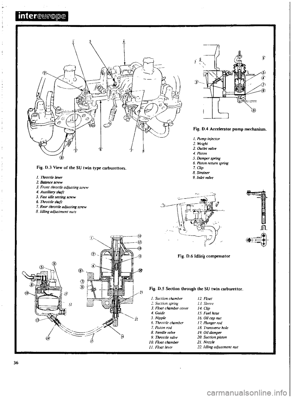
View
of
the
SU
twin
type
carburettors
1
Throttle
r
2
JaJana
crew
Front
throttle
adjusting
screw
4
AuxiliDry
shoft
5
Ftnt
idle
selling
lCn
W
6
Throttle
shaft
7
Rear
throttle
adjusrint
screw
8
Idling
adjustment
nuts
m
11
j
G
36
B
l
D
i
I
lli
9
3
J6
6
Fig
D
4
Accelerator
pump
mechanism
J
Pump
injuror
2
Weight
2
Outklvolve
4
Piston
5
Damper
spring
6
Piston
return
spring
7
Clip
8
Strainu
9
Inlet
lmlJe
I
Fig
D
6
Idling
compensator
1
lit
21
Fig
D
5
Section
through
the
SU
twin
carbureUor
J
Suction
chamber
Suctiull
spring
3
Hoat
chamber
corer
4
Guide
5
Nipple
6
Throttle
chamber
7
Piston
rod
8
Needle
valve
9
T7trollle
l
ob
e
J
O
Float
chtzmber
J
1
Float
Iel
cr
J
2
Float
13
Sleel
e
4
aip
5
Fuel
hose
6
Oil
cap
nut
1
7
Plunger
rod
18
Transvtne
hole
J
9
Oil
domJX
20
Suction
piston
21
Nozzle
Idling
adjustment
nut
Page 68 of 171
cage
Mcasure
the
clearance
between
the
rear
face
of
thc
side
gear
and
the
differential
cage
as
shown
in
Fig
G
ll
and
if
necessary
use
a
tluust
washer
which
will
given
a
clearance
of
0
1
0
2mm
0
004
0
008
in
Fit
the
pinion
shaft
lock
pin
and
secure
it
by
caulking
with
a
punch
Lubricate
the
gear
teeth
and
check
the
gear
for
freedom
of
rotation
Install
the
crown
wheel
in
the
differential
cage
and
insert
the
bolts
with
new
lock
straps
Tap
the
head
of
each
bolt
lightly
and
tighten
the
bolts
in
a
diagonal
pattern
to
a
torque
reading
of
7
0
8
0
kgm
51
58Ib
ft
Measure
the
width
of
the
side
bearings
before
installing
them
Place
a
weight
of
2
5
kg
5
5
1b
on
the
bearings
and
check
the
nominal
width
which
should
be
20mm
0
787
in
Press
the
side
bearings
into
the
differential
cage
Adjustment
of
drive
pinion
preload
This
adjustment
is
carried
out
without
fitting
the
oil
seal
Press
the
front
and
rear
bearing
outer
races
into
the
gear
carrier
and
fit
the
pinion
height
adjusting
washer
Fig
G
12
the
shims
and
the
rear
bearing
inner
race
onto
a
dummy
shaft
special
tool
ST
31
120000
The
old
washers
and
shims
can
be
re
used
if
the
tooth
contact
pattern
was
found
to
be
correct
on
the
pre
dismantling
check
Fit
the
drive
pinion
bearing
spacer
the
washer
ans
special
collar
5T
312140000
or
5T
31500000
and
the
drive
flange
on
to
the
dummy
shaft
Tighten
the
drive
pinion
nut
to
a
torque
reading
of
17
20
kgm
123
145
Ib
ft
Measure
the
drive
pinion
bearing
pre
load
and
select
washers
and
spacers
to
give
a
pre
load
of
7
1
0
kg
cm
6
9Ib
in
with
new
bearings
or
3
6
kg
cm
2
6
5
Ib
in
with
used
bearings
Adjusting
spacers
are
available
in
lengths
of
56
2
57
2
mm
2
2126
2
2520
in
and
adjusting
washers
in
thicknesses
of
59
2
31
mm
0
1020
0
0909
in
Adjustment
of
pinion
height
The
pinion
height
or
distance
of
the
face
of
the
pinion
to
the
axis
of
the
crownwheel
is
adjusted
by
the
thickness
of
the
adjusting
washer
behind
the
drive
pinion
gcar
The
drive
pinion
has
a
tolerance
mark
etched
on
its
face
this
tokrance
is
accompanied
by
a
or
sign
to
show
the
deviation
from
the
nominal
dimension
Thc
plus
sign
indicates
that
the
nominal
distance
must
be
increased
and
the
minus
sign
that
it
mllst
be
decreased
The
tolerances
are
shown
in
Fig
G
I3
The
pinion
height
can
be
adjusted
using
the
original
adjusting
washer
and
shims
between
the
rear
bearing
cone
and
the
drive
pinion
Install
the
setting
gauge
5T
31210000
on
the
carrier
with
the
dummy
pinion
installed
Sce
Fig
G
14
Measure
the
clearance
between
the
head
of
the
dummy
shaft
and
the
tip
of
the
setting
g
wge
using
a
feeler
gauge
as
shown
in
Fig
G
15
The
clearance
is
also
shown
at
the
point
T
in
Fig
G
14
The
required
thickness
of
the
adj
lsting
washer
can
be
obtained
using
the
following
formula
S
W
T
H
x
0
01
0
20
Where
W
thickness
of
inserted
shims
and
washers
T
Measured
thickness
H
Figure
engraved
on
pinion
head
o
S
Required
thickn
ss
of
washers
and
shims
A
typical
example
is
given
below
w
20
1
20
T
H
S
340
0
24
2
x
0
01
0
20
3
40
mm
0
24
mm
3
46
mm
An
adjusting
washer
rrlust
be
selected
which
is
nearest
in
thickness
to
the
value
of
3
46mm
Adjusting
washers
are
available
in
thicknesses
of
3
09mm
0
01217
in
to
3
66m
0
1441
in
for
the
l800cc
models
and
in
thicknesses
of
O
2
and
2
4mm
0
787
0
866
and
0
945
in
for
the
1400
and
1600
cc
models
Fit
the
selected
adjusting
washer
and
shims
to
the
drive
pinion
and
press
on
the
rear
bearing
inner
race
Install
the
drive
pinion
into
the
differential
carrier
together
with
the
bearing
spacer
and
washer
the
front
bearing
inner
race
and
the
front
bearing
pilot
spacer
Fit
the
drive
flange
and
washer
on
the
drive
pinion
and
secure
them
with
the
pinion
nut
Tighten
the
nut
to
a
torque
reading
of
17
20
kgm
123
145Ib
ft
SIDE
BEARING
SHIMS
Selecting
The
side
bearing
pre
load
must
be
adjusted
with
selected
shims
if
the
differential
carrier
the
cage
the
side
bearings
or
the
bearing
covers
have
been
renewed
The
required
thickness
of
the
shims
can
be
obtained
using
the
following
formula
and
referring
to
Fig
G
l
5
T1
left
side
bearing
A
C
GI
D
E
H
x
0
01
0
76
T2
right
side
bearing
B
D
G2
F
H
x
0
01
0
76
Where
A
B
C
D
E
F
The
figure
on
the
differential
carrier
The
figure
on
the
differential
cage
The
differences
in
width
of
the
left
or
right
hand
bearings
against
the
nominal
width
of
20
0mm
0
7874
in
given
in
units
of
1
100
mm
Gl
G2
H
The
figure
on
the
side
cover
The
figure
on
the
crownwheel
The
A
B
C
D
G
and
H
figures
indicate
the
dimensional
variations
in
units
of
1
100
mm
fr
Jm
the
standard
measurement
An
example
of
the
calculations
to
decide
the
thickness
of
shim
required
is
given
below
Where
A
I
B
2
C
2
D
1
GI
3
G2
1
E
O
Olmm
F
O
02mm
H
Left
side
bearing
Tl
A
C
G
1
D
H
x
0
01
0
76
E
I
3
1
2
x
0
01
0
76
0
01
0
8mm
Right
side
bearing
T2
B
D
G2
H
x
0
01
0
76
F
2
I
I
2
x
0
01
0
76
0
02
0
8mm
67