tow bar DATSUN B110 1969 Service Repair Manual
[x] Cancel search | Manufacturer: DATSUN, Model Year: 1969, Model line: B110, Model: DATSUN B110 1969Pages: 136, PDF Size: 5.64 MB
Page 78 of 136

pront
Suspension
Qj
@
@
I
Strut
mounting
Insulator
2
Strut
mounllng
bearing
3
Upper
pnng
o
r
at
4
Oumpu
rubblf
5
DU
tlOVU
6
P
ton
rod
7
F
ool
pring
8
Irut
embly
q
Hub
b
t
mbly
10
5pmdh
II
Ball
JOint
12
Trd
nwu
link
1
J
Tln
lon
rod
14
StJblluLr
15
SU
p
mIOn
mlmbt
r
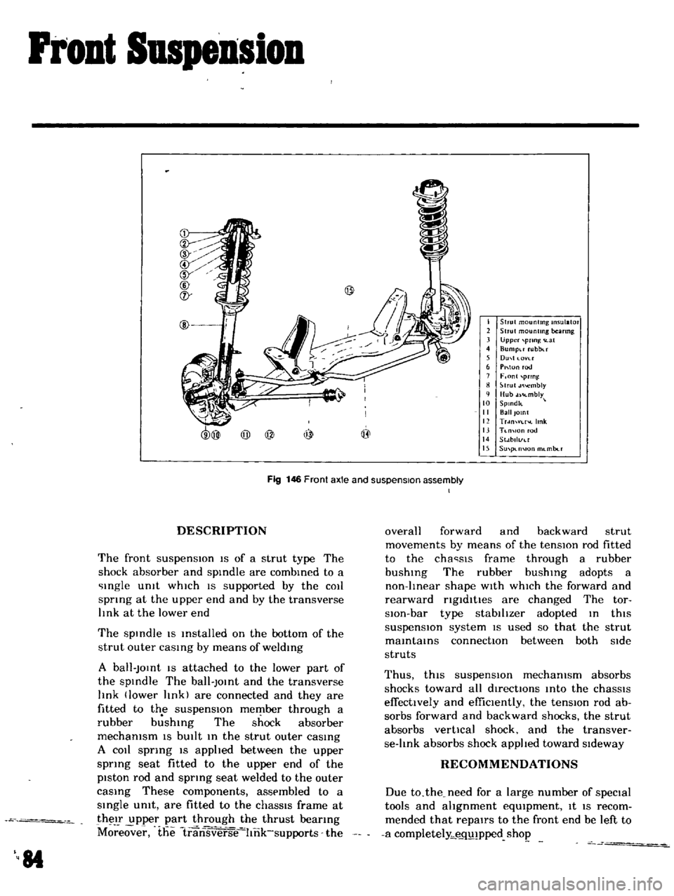
Fig
146
Front
axle
and
suspension
assembly
I
DESCRIPTION
The
front
suspensIOn
IS
of
a
strut
type
The
shock
absorber
and
spIndle
are
combIned
to
a
Ingle
Unit
whIch
IS
supported
by
the
COIl
spnng
at
the
upper
end
and
by
the
transverse
lInk
at
the
lower
end
The
spIndle
IS
Installed
on
the
bottom
of
the
strut
outer
caSIng
by
means
of
weldIng
A
ball
JOInt
IS
attached
to
the
lower
part
of
the
spIndle
The
ball
JOInt
and
the
transverse
lInk
lower
lInk
are
connected
and
they
are
fitted
to
the
suspensIOn
member
through
a
rubber
b
shIng
The
shock
absorber
mechanism
IS
bUIlt
In
the
strut
outer
caSIng
A
COIl
sprIng
IS
apphed
between
the
upper
sprIng
seat
fitted
to
the
upper
end
of
the
piston
rod
and
spring
seat
welded
to
the
outer
caSIng
These
components
assembled
to
a
SIngle
umt
are
fitted
to
the
chaSSIS
frame
at
their
upper
part
through
the
thrust
beanng
M
eover
the
1ransverse
hnk
supports
the
84
overall
forward
and
backward
strut
movements
by
means
of
the
tensIOn
rod
fitted
to
the
cha
sls
frame
through
a
rubber
bushIng
The
rubber
bushIng
adopts
a
non
lInear
shape
WIth
whICh
the
forward
and
rearward
ngldltles
are
changed
The
tor
slOn
bar
type
stabilIzer
adopted
In
thiS
suspensIOn
system
IS
used
so
that
the
strut
maIntaInS
connectIOn
between
both
Side
struts
Thus
thiS
suspensIOn
mechanism
absorbs
shocks
toward
all
directIOns
Into
the
chaSSIS
effectively
and
effiCIently
the
tensIOn
rod
ab
sorbs
forward
and
backward
shocks
the
strut
absorbs
vertical
shock
and
the
transver
se
lInk
absorbs
shock
applIed
toward
SIdeway
RECOMMENDATIONS
Due
to
the
need
for
a
large
number
of
speCial
tools
and
ahgnment
eqUIpment
It
IS
recom
mended
that
repairs
to
the
front
end
be
left
to
a
completely
e
q
pped
shop
Page 106 of 136

Bod
Work
TRUNK
LID
LOCK
Removal
Loosen
m
tallatlOn
bolts
and
remove
the
tl
Iker
and
lock
from
the
body
Remove
the
leaf
chp
lu
ed
to
secure
the
trunk
hd
lock
cylmder
on
the
body
and
remove
the
trunk
lId
lock
cylIndCl
Adjustment
Sedan
When
adjustmg
engagement
between
the
lock
and
tnker
set
the
lock
statlOnanly
and
properly
adjust
stnker
poSitIOn
Adjustmg
stroke
toward
left
and
nght
SIdes
dIrectIOn
IS
0
890
m
and
03150
m
toward
vertical
dIrectIOn
VAN
j
1
II
U8
Coupe
When
adju
tmg
engagement
between
the
lock
and
stnker
adjust
stnker
poSitIOn
toward
left
and
right
Sides
adju
tmg
stroke
02362
m
and
lock
pOSitIOn
for
vertical
directIOn
ad
justmg
stroke
03
50
m
Tlghtemng
torque
Lock
and
stnker
fixmg
bolt
o
87
to
45
ft
lb
TRUNK
LID
TORSION
BAR
The
procedures
of
m
tallIng
torsIOn
bar
are
mdlcated
as
follows
Note
When
installing
the
torsion
bar
u
te
a
torsIOn
bar
wrench
J
tl
l
11
4
i
0
t
b
f
I
Back
door
hUlle
tomon
bOT
2
BlCk
door
hmge
3
Back
door
4
Back
door
lock
rod
l
Lock
6
Stnker
7
Stnker
shun
8
Back
door
side
dovetad
9
Side
dovetl1l
tllm
10
Back
door
bumper
II
Back
door
bumper
plate
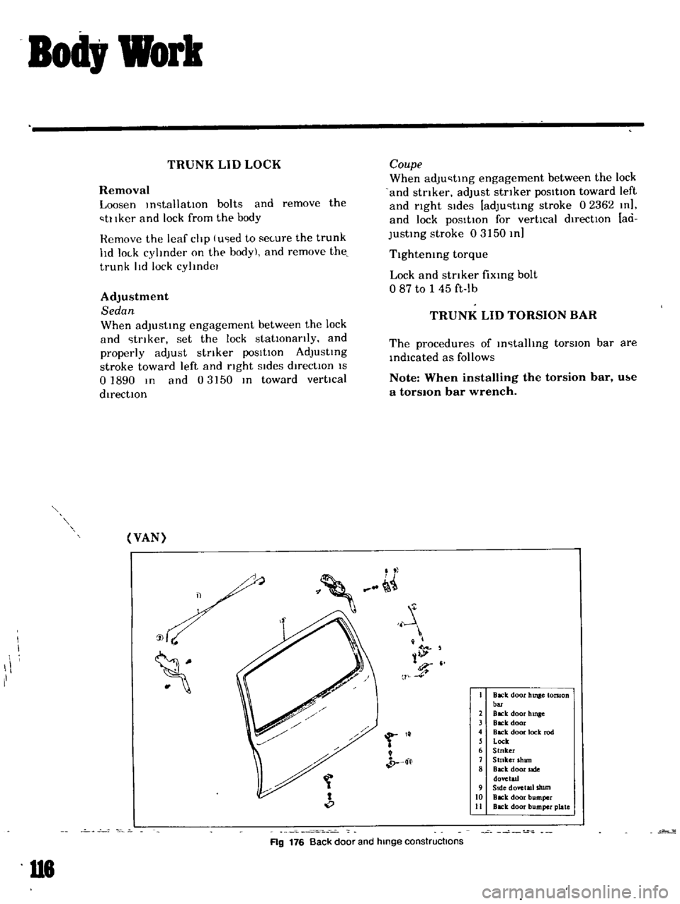
Ag
176
Back
door
and
hinge
constructions