oil DATSUN B110 1973 Service Repair Manual
[x] Cancel search | Manufacturer: DATSUN, Model Year: 1973, Model line: B110, Model: DATSUN B110 1973Pages: 513, PDF Size: 28.74 MB
Page 5 of 513
AUTOMATIC
TRANSMISSION
1
1
1
I
L
@
CD
@
@
ID
@
@
h
r
H
@
@
@
@
@
@
@
4
@
@
t
I
fA
TIl70
4
t
ill
pJrP
I
Transmission
ase
II
Governor
Tightening
torque
T
of
@T
0
5
to
0
7
2
Oil
pump
12
Output
shaft
bolts
and
nuts
kg
rn
ft
Ib
3
6
to
5
1
3
Front
clutch
13
Rear
xtcnsion
@T
0
8
to
1
0
@T
2
0
to
2
5
4
Band
brake
14
Oil
pan
@T
5
8
to
7
2
14
to
18
5
Rear
clutch
15
Control
valve
4
to
5
@T
1
3
to
1
8
6
Front
planetary
gt
ar
16
Input
shaft
@T
29
to
36
9
4
to
13
7
Rear
planetary
gear
17
Torque
converter
6
5
to
7
5
@T
0
55
to
0
75
8
One
way
clutch
18
Converter
housing
@T
47
to
54
4
0
to
5
4
9
Low
Reverse
brake
19
Drive
plate
0
6
h
Q
8
Q
T
0
25
to
0
35
10
Oil
distributor
4
3
to
5
8
1
9
to
2
5
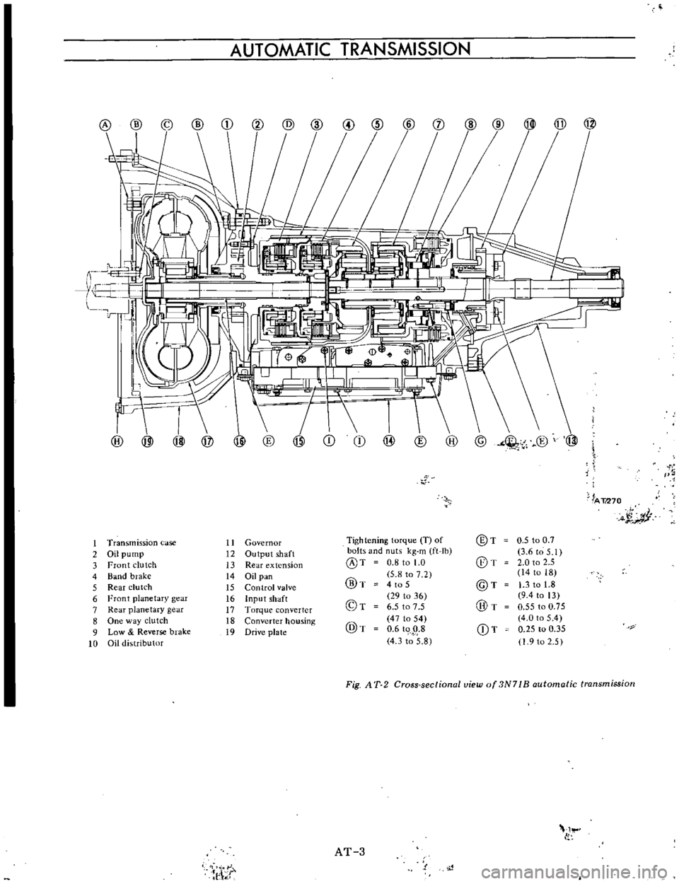
Fig
AT
2
Cross
sectional
uiew
of
3N71
B
automatic
transmission
I
AT
3
l
t
Page 6 of 513
CHASSIS
HYDRAULIC
CONTROL
SYSTEM
l
FUNCTIONS
OF
HYDRAULIC
CONTROL
UNIT
AND
VALVES
Oil
pump
Manual
linkage
Vacuum
diaphragm
Downshift
solenoid
Governor
valve
Control
valve
assembly
HYDRAULIC
SYSTEM
AND
MECHANICAL
OPERATION
CONTENTS
P
range
Park
R
range
Reverse
N
range
Neutral
D
range
Low
gear
D2
range
2nd
gear
D3
range
Top
gear
D
range
kick
down
2
range
2nd
gear
1
range
Low
gear
12
range
2nd
gear
AT
4
AT
4
AT
5
AT
5
AT
5
AT
5
AT
7
AT13
AT
14
AT
16
AT
18
AT
20
AT
22
AT
24
AT
26
AT
28
AT
30
AT
32
FUNCTIONS
OF
HYDRAULIC
CONTROL
UNIT
AND
VALVES
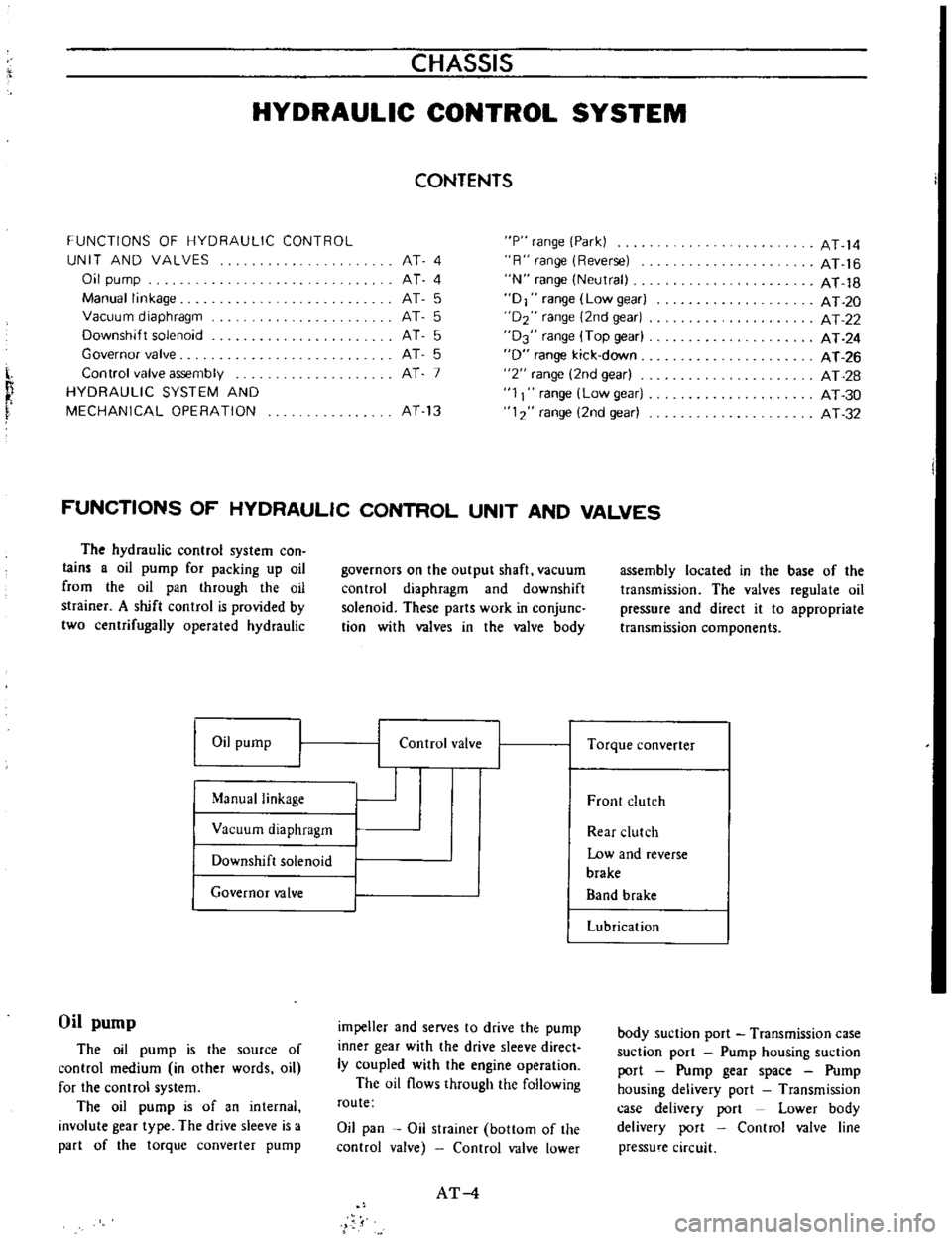
The
hydraulic
control
system
con
lain
a
oil
pump
for
packing
up
oil
from
the
oil
pan
through
the
oil
strainer
A
shift
control
is
provided
by
two
centrifugally
operated
hydraulic
Oil
pump
Manual
linkage
Vacuum
diaphragm
Downshift
solenoid
Governor
valve
Oil
pump
The
oil
pump
is
the
source
of
control
medium
in
other
words
oil
for
the
control
system
The
oil
pump
is
of
an
internal
involute
gear
type
The
drive
sleeve
is
a
part
of
the
torque
converter
pump
governors
on
the
output
shaft
vacuum
control
diaphragm
and
downshift
solenoid
These
parts
work
in
conjunc
tion
with
valves
in
the
valve
body
I
I
Control
valve
impeller
and
serves
to
drive
the
pump
inner
gear
with
the
drive
sleeve
direct
ly
coupled
with
the
engine
operation
The
oil
flows
through
the
following
route
Oil
pan
Oil
strainer
bottom
of
the
control
valve
Control
valve
lower
AT
4
assembly
located
in
the
base
of
the
transmission
The
valves
regulate
oil
pressure
and
direct
it
to
appropriate
transmission
components
I
Torque
converter
Front
clutch
Rear
clutch
Low
and
reverse
brake
Band
brake
Lubrication
body
suction
port
Transmission
case
suction
port
Pump
housing
suction
port
Pump
gear
space
Pump
housing
delivery
port
Transmission
case
delivery
port
Lower
body
delivery
port
Control
valve
line
pressure
circuit
Page 7 of 513
AUTOMATIC
TRANSMISSION
Manual
linkage
The
hand
lever
motion
The
hand
lever
is
located
in
the
driver
s
com
part
men
mechanically
transmitted
from
the
remote
control
linkage
is
further
transmitted
to
the
inner
manual
lever
in
the
transmission
case
from
the
range
selector
lever
in
the
right
center
poc
tion
of
the
transmission
case
through
the
manual
shaft
The
inner
manual
lever
is
thereby
turned
A
pin
installed
on
the
bottom
of
the
inner
manual
lever
slides
the
manu
al
valve
spool
of
the
control
valve
and
thus
the
spool
is
appropriately
posi
lioned
opposing
to
each
select
position
The
parking
rod
pin
is
held
in
the
groove
on
the
top
of
the
inner
manual
plate
The
parking
rod
pin
operates
the
rod
at
p
range
and
operates
the
mechanical
lock
system
Moreover
the
above
described
manual
shaft
is
equipped
with
an
inhibitor
switch
A
rotor
inside
the
inhibitor
switch
rotates
in
response
to
each
range
When
the
range
is
selected
at
p
or
N
the
rotor
closes
the
starter
magnet
circuit
so
that
the
engine
can
be
started
When
the
range
is
selected
at
R
the
rotor
closes
the
back
up
lamp
circuit
and
the
back
up
lamp
lights
Vacuum
diaphragm
The
vacuum
diaphragm
is
installed
un
the
left
center
portion
of
the
transmission
case
The
internal
con
struction
of
the
vacuum
diaphragm
is
as
follows
A
rubber
diaphragm
forms
a
partition
in
the
center
The
engine
intake
manifold
negative
pressure
led
through
vacuum
tube
and
spring
force
are
applied
to
the
front
surface
of
the
rubber
diaphragm
and
atmospheric
pressure
is
applied
to
the
back
surface
A
difference
between
pressure
applied
to
the
front
and
back
surfaces
be
comes
a
vacuum
reaction
and
thus
the
throttle
valve
of
the
control
valve
inside
the
transmission
case
is
op
erated
When
accelerator
pedal
is
fully
de
pressed
and
the
carburetor
is
fully
upened
but
the
engine
speed
is
not
1
Housing
2
Cover
3
Outer
gear
AT071
4
Inner
gear
5
Crescent
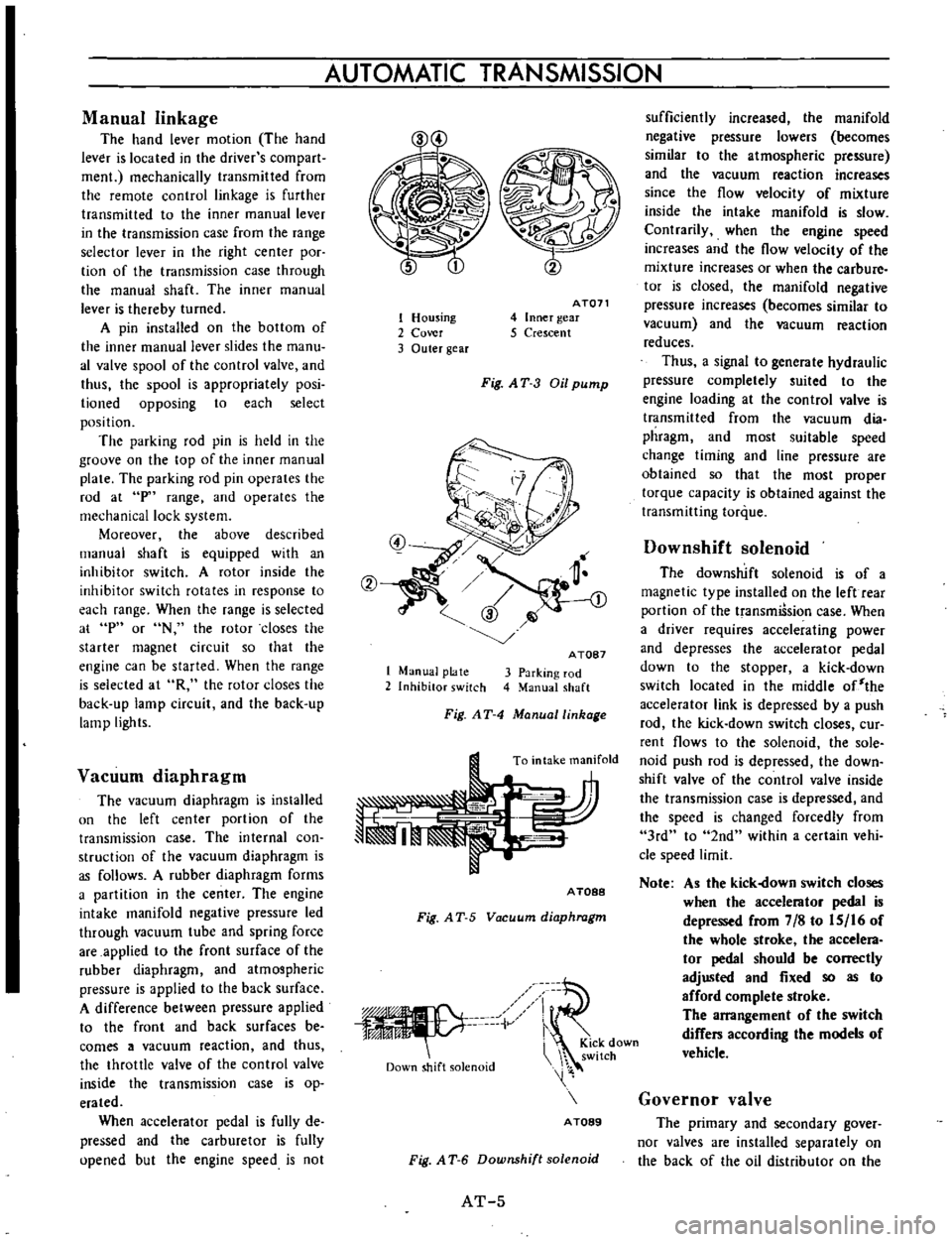
Fig
AT
3
Oil
pump
1
Manual
plate
2
Inhibitor
switch
A
TOB7
3
Parking
rod
4
Manual
shaft
Fig
AT
4
Manuallinhage
To
intake
manifold
A
TOBB
Fig
A
T
5
Vacuum
diaphragm
iV
Down
shift
solenoid
i
KiCk
down
switch
A
TOB9
Fig
A
T
6
Downshift
solenoid
AT
5
sufficiently
increased
the
manifold
negative
pressure
lowers
becomes
similar
to
the
atmospheric
pressure
and
the
vacuum
reaction
increases
since
the
flow
velocity
of
mixture
inside
the
intake
manifold
is
slow
Contrarily
when
the
engine
speed
increases
and
the
flow
velocity
of
the
mixture
increases
or
when
the
carbure
tor
is
closed
the
manifold
negative
pressure
increases
becomes
similar
to
vacuum
and
the
vacuum
reaction
reduces
Thus
a
signal
to
generate
hydraulic
pressure
completely
suited
to
the
engine
loading
at
the
control
valve
is
transmitted
from
the
vacuum
dia
phragm
and
most
suitable
speed
change
timing
and
line
pressure
are
obtained
so
that
the
most
proper
torque
capacity
is
obtained
against
the
transmitting
torque
Downshift
solenoid
The
downshift
solenoid
is
of
a
magnetic
type
installed
on
the
left
rear
portion
of
the
transmiSsion
case
When
a
driver
requires
accelerating
power
and
depresses
the
accelerator
pedal
down
to
the
stopper
a
kick
down
switch
located
in
the
middle
of
the
accelerator
link
is
depressed
by
a
push
rod
the
kick
down
switch
closes
cur
rent
flows
to
the
solenoid
the
sole
noid
push
rod
is
depressed
the
down
shift
valve
of
the
control
valve
inside
the
transmission
case
is
depressed
and
the
speed
is
changed
forcedly
from
3rd
to
2nd
within
a
certain
vehi
cle
speed
limit
Note
As
the
kick
own
switch
closes
when
the
accelerator
pedal
is
depressed
from
7
8
to
IS
16
of
the
whole
stroke
the
accelera
tor
pedal
should
be
correctly
adjusted
and
fixed
so
as
to
afford
complete
stroke
The
arrangement
of
the
switch
differs
according
the
models
of
vehicle
Governor
valve
The
primary
and
secondary
gover
nor
valves
are
installed
separately
on
the
back
of
the
oil
distributor
on
the
Page 8 of 513
I
transmission
output
shaft
They
op
erate
in
the
same
speed
as
that
of
the
output
shaft
In
other
wotds
they
operate
at
a
speed
in
proportion
to
the
vehicle
speed
To
those
valves
the
line
pressure
is
applied
as
the
input
ftom
the
control
valve
through
the
transmission
case
rear
flange
and
oil
distributor
The
governor
pressure
in
proportion
to
the
output
shaft
speed
vehicle
speed
is
led
to
the
shift
valve
of
the
control
valve
through
inverse
rou
te
as
the
output
and
thus
the
speed
change
and
the
line
pressure
are
controlled
Operation
of
secondary
governor
valve
The
secondary
valve
is
a
control
valve
which
receives
line
pressure
I
and
controls
the
governor
pressure
When
the
manual
valve
is
selected
D
2
or
1
range
line
pres
sure
is
applied
to
the
ring
shape
area
of
f
this
valve
from
circuit
I
and
this
valve
is
depressed
toward
the
center
side
Movement
of
this
valve
to
a
certain
position
closes
the
circuit
from
I
to
15
simultaneously
while
mak
ing
a
space
from
the
15
to
the
center
drain
port
and
pressure
in
the
circuit
IS
is
lowered
When
the
vehicle
is
stopped
and
the
centrifugal
force
of
this
valve
is
zero
the
valve
is
balanced
In
this
a
gover
nor
pressure
which
is
balanced
with
the
spring
force
occurs
on
the
15
When
the
vehicle
is
started
and
the
centrifugal
force
increases
this
valve
slightly
moves
to
the
outside
and
when
the
space
from
I
to
15
increases
space
from
the
15
to
the
drain
port
reduces
simultaneously
As
the
result
governor
pressure
of
the
15
increases
and
the
governor
pres
sure
is
balanced
with
the
sum
of
centrifugal
force
and
the
spring
force
The
governor
pressure
thus
changt
s
in
response
to
the
vehicle
speed
change
centrifugal
force
Operation
of
primary
governor
valve
The
valve
is
an
ON
OFF
valve
which
closes
the
governor
pressure
15
regulated
by
the
secondary
gover
CHASSIS
nor
valve
when
the
vehicle
speed
reaches
the
minimum
speed
and
when
the
vehicle
speed
exceeds
a
certain
level
open
the
governor
and
forwards
the
governor
pressure
15
to
the
control
valve
When
the
vehicle
is
stopped
the
governor
pressure
is
zero
However
when
the
vehicle
is
running
slowly
this
valve
is
depressed
to
the
center
side
and
the
groove
to
the
IS
is
closed
since
the
governor
pressure
applied
to
the
ring
shape
area
is
higher
than
the
centrifugal
force
of
this
valve
When
the
governor
speed
exceeds
cer
tain
revolution
the
governor
pressure
in
the
circuit
15
also
increases
How
ever
as
the
centrifugal
force
increases
and
exceeds
the
governor
pressure
this
valve
moves
toward
the
outside
and
the
governor
pressure
is
transmitted
to
the
circuit
15
Two
different
valves
are
employed
in
the
governor
so
that
it
will
inde
pendently
control
the
speed
at
high
speed
and
at
low
speed
That
is
within
the
low
speed
range
the
governor
pressure
is
not
generated
owing
to
the
primary
valve
whereas
at
the
high
speed
range
above
the
break
point
a
governor
pressure
regula
ted
by
the
sec0Hdary
valve
is
introduced
The
break
point
is
the
point
at
which
the
function
of
one
of
the
govp
rnors
is
transferred
to
the
other
whee
the
speed
changes
from
the
w
speed
range
to
the
high
speed
range
To
con
trol
valve
Governor
pressure
tiS
y
ID
t
4
From
control
valve
Line
pressure
I
J
I
Primary
governor
2
Secondar
governor
3
Governor
valve
body
AT090
4
Oil
distributor
5
Output
shaft
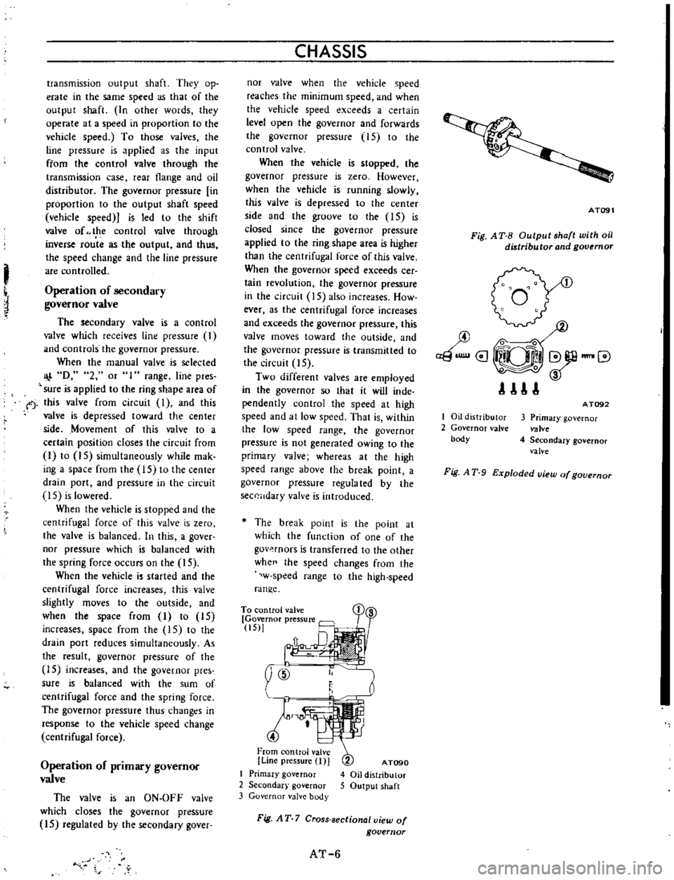
Fig
AT
7
Cross
sectional
view
of
governor
AT
6
AT091
Fig
A
T
B
Output
shaft
with
oil
distributor
and
governor
I
Oil
distributor
2
Governor
valve
body
AT092
3
Primary
governor
valve
4
Secondary
governor
valve
Fig
A
T
9
Exploded
uiew
of
gouernor
Page 10 of 513
LIMITED
WARRANTY
Your
Hurst
product
warranted
per
table
below
Irom
dale
01
purchase
against
defects
materinl
and
workmanship
Dur
ing
this
period
luch
defects
will
be
repoired
the
product
will
be
chllnQl
d
at
Huut
option
without
charge
This
war
onty
does
damiilge
used
bv
milu
lI
alteration
negligence
ALL
IMPLIED
WARRANTIES
INCLUDING
BUT
NOT
LIMITED
TO
WARRANTIES
OF
FITNESS
AND
MER
CHANTABllITV
ARE
LIMITED
IN
DURATION
TO
A
PE
RIOO
ENDING
WITH
THE
PERIOD
OF
THE
CORRESPOND
ING
EXPRESS
LIMITED
WARRANTY
AS
SET
FORTH
BE
LOW
UNDER
NO
CIRCUMSTANCES
WILL
HURST
BE
RE
SPONSI8LE
FOR
INCIDENTAL
OR
CONseQUENTIAL
DAMAGES
ARISING
FADM
OR
IN
CONNECTION
WITH
THE
INSTALLATION
OR
USE
OF
ANY
HURST
PRODUCT
Some
tates
do
not
allow
limitations
on
how
long
implied
warranty
lasts
do
not
allow
for
tha
Axclusion
limitation
of
incidental
nnlequantial
damages
the
above
limitations
may
not
apply
to
you
This
Warranty
givlIs
you
specific
legal
righta
and
you
may
also
have
other
rights
which
Vpry
from
state
to
state
Return
of
the
Product
Registration
Card
nOt
nndition
precedent
Warranty
nvAraga
and
performance
HURST
WARRANTY
PERIODS
from
cJ
ffI
of
purch
lt
I
Shift
rs
Air
Shocks
12monttlt
12
OOOmil
or
12month1
whch
ver
lim
gOd
vl
12montl1s
12montl1s
12montl1s
Aoeellories
Tr
Rlmission
Oil
Coolers
Autom
tic
Tr
umitsion
P
rh
Scl1i
f
rPloductt
J
c
udinll
producrr
u
d
fOT
rw
ingl
Bring
the
product
or
nd
it
pOttage
preplidf
Hurst
Performance
Inc
or
IIuthorized
doaler
If
you
end
the
product
pleas
write
letter
IIxplaining
the
01
your
difficulty
HURST
PERFORMANCE
INC
50
West
Street
Road
Warminnl
r
PennsylvlInlll18974
In
tha
ellenl
you
have
any
questions
rning
IInd
of
the
product
rning
pleese
write
Customer
Satisfaction
Depertment
lit
above
addreu
How
To
Get
Quick
Service
1
Peck
your
Hunt
product
r
nrefully
good
IriOn
with
plenty
of
newspape
s
u
celsior
padding
all
mund
it
and
till
lIly
Oamllge
transit
not
nv
red
by
the
warranty
2
Carefully
prinl
the
lrton
thlll
name
Ind
Iddrllu
01
Hurl
above
Don
t
forget
your
return
addreu
3
Put
I
tter
showing
desired
n
lIlope
addressed
HUrl
above
In
your
lettllr
plellSe
be
to
give
full
formation
such
date
and
place
of
purchase
your
full
name
IInd
address
and
the
reptllrS
d
sired
4
PASTE
ENVELOPE
TO
PACKAGE
S
Put
First
CIBst
stamp
nvelope
IInd
Parcel
Pall
stamps
package
then
mail
The
Post
Office
will
tell
yOU
the
proper
amount
of
postage
and
against
Iou
the
mDils
z
it
l
l
III
0
1168
a
o
o
i
g
I
o
0
DO
o
0
I
t
i
lL
5
I
0
q
II
1
I
if
18
0
l
q
t
tJ
w
j
b
00000
i
I
a
1
I
S
z
I
i
o
i
i
I
c
q
3
10
w
ol
8
q
1
5
lj
I
u
i
i
i
@
z
i
i
tii
I
f
8
ts
I
5
i
a
s
fl
00000000000000
C
a
0
u
Z
o
a
ti
a
w
a
u
J
C
o
a
lIt
c
l
l
c
l
J
Ci
I
J
I
I
a
1111
i
Z
iRI
1
Ii
iD
i
8
1
I
1I
o
0
1
o
011
Dl
DI
oj
o
Page 11 of 513
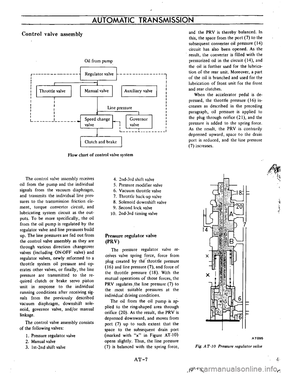
Control
valve
assembly
AUTOMATIC
TRANSMISSION
Oil
from
pump
ru
nn
i
I
I
I
Throttle
valve
I
I
1
m
nn
I
Auxiliary
valve
I
Regulator
valve
j
Manual
valve
I
Uoe
pressure
Speed
change
L
I
Governor
valve
I
I
valve
J
1
1
Clutch
and
brake
Flow
chart
of
control
valve
system
The
control
valve
assembly
receives
oil
from
the
pump
and
the
individual
signals
from
the
vacuum
diaphragm
and
transmits
the
individual
line
pres
sures
to
the
transmission
friction
ele
ment
torque
converter
circuit
and
lubricating
system
circuit
as
the
out
puts
To
be
more
specifically
the
oil
from
the
oil
pump
is
regulated
by
the
regulator
valve
and
line
pressures
build
up
The
line
pressures
are
fed
out
from
the
control
valve
assembly
as
they
are
through
various
direction
changeover
valves
including
ON
OFF
valve
and
regulator
valves
newly
reformed
to
a
throttle
system
oil
pressure
and
op
crates
other
valves
or
finally
the
line
pressure
are
transmitted
to
the
re
quired
clutch
or
brake
servo
piston
unit
in
response
to
the
individual
running
conditions
after
receiving
sig
nals
from
the
previously
described
vacuum
diaphragm
downshift
sole
noid
governor
valve
and
or
manual
linkage
The
control
valve
assembly
consists
of
the
following
valves
Pressure
regulator
valve
2
Manual
valve
3
1st
2nd
shift
valve
4
2nd
3rd
shift
valve
S
Pressure
modifier
valve
6
Yacuum
throttle
valve
7
Throttle
back
up
valve
8
Solenoid
downshift
valve
9
Second
lock
valve
0
2nd
3rd
timing
valve
Pressure
regulator
valve
PRV
The
pressure
regulator
valve
re
ceives
valve
spring
force
force
from
plug
created
by
the
throttle
pressure
16
and
line
pressure
7
and
force
of
the
throttle
pressure
18
With
the
mutual
operations
of
those
forces
the
PRY
regulates
the
line
pressure
7
to
the
most
suitable
pressures
at
the
individual
driving
conditions
The
oil
from
the
oil
pump
is
ap
plied
to
the
ring
shaped
area
through
orifice
20
As
the
result
the
PRY
is
depressed
downward
and
moves
from
port
7
up
to
such
extent
that
the
space
to
the
subsequent
drain
port
marked
with
x
in
Figure
AT
10
opens
slightly
Thus
the
line
pressure
7
is
balanced
with
the
spring
force
AT
7
and
the
PRY
is
thereby
balanced
In
this
the
space
from
the
port
7
to
the
subsequent
converter
oil
pressure
14
circuit
has
also
been
opened
As
the
result
the
converter
is
filled
with
the
pressurized
oil
in
the
circuit
14
and
the
oil
is
further
u
d
for
the
Iubrica
tion
of
the
rear
unit
Moreover
a
part
of
the
oil
is
branched
and
used
for
the
lubrication
of
front
unit
for
the
front
and
rear
clutches
When
the
accelerator
pedal
is
de
pressed
the
throttle
pressure
16
in
creases
as
described
in
the
preceding
paragraph
oil
pressure
is
applied
to
the
plug
through
orifice
21
and
the
pressure
is
added
to
the
spring
force
As
the
result
the
PRY
is
contrarily
depressed
upward
space
to
the
drain
port
is
reduced
and
the
line
pressure
7
increases
Afl
II
Jwi
06
A
J
L
I
7
I
tf
Iij
BL
i
il
J
jti
r
x
r
1
J
I
l
I
X
6
C
l
o
ii
J
f
A
T09S
Fig
AT
10
Pressure
regulator
value
tr
r
Page 13 of 513
Low
in
the
range
I
is
led
to
the
low
and
reverse
clutch
from
the
line
pressure
5
through
the
line
pressure
12
and
at
the
same
time
the
same
is
led
to
the
left
end
spring
unit
Consequently
although
the
go
vernor
pressure
increases
the
valve
is
still
depressed
toward
the
right
and
the
SFV
is
fixed
in
the
Low
posi
tion
When
kicked
down
at
the
2nd
speed
the
SDV
operates
and
the
line
pressure
13
depresse
the
FSV
to
ward
the
right
Although
the
governor
pressure
15
is
considerably
high
the
valve
is
depressed
completely
toward
the
right
and
the
FSV
is
returned
to
the
Low
position
This
operation
is
called
Kick
down
shift
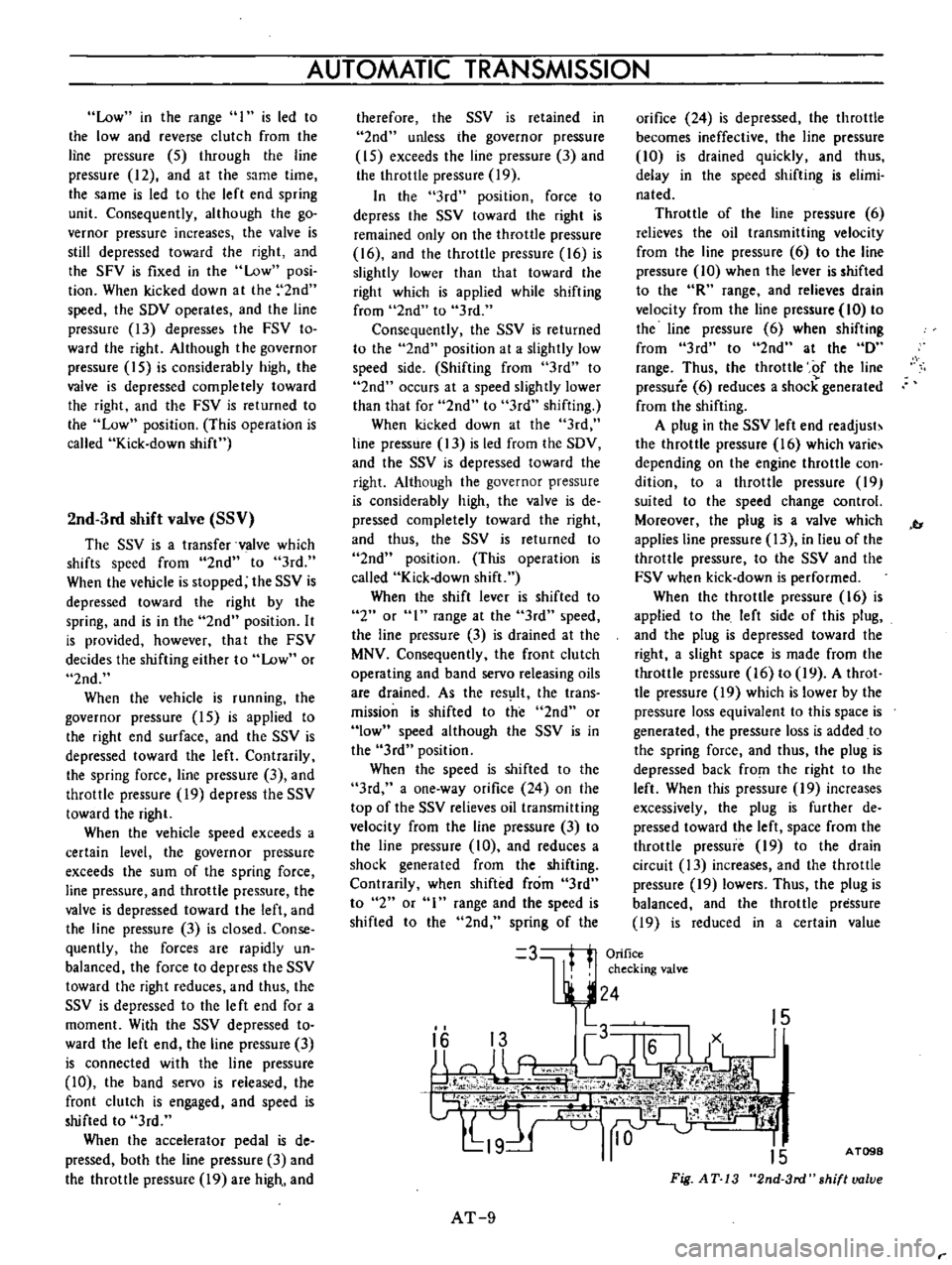
2nd
3rd
shift
valve
SSV
The
SSV
is
a
transfer
vaIve
which
shifts
speed
from
2nd
to
3rd
When
the
vehicle
is
stopped
the
SSV
is
depressed
toward
the
right
by
the
spring
and
is
in
the
2nd
position
It
is
provided
however
that
the
FSV
decides
the
shifting
either
to
Low
or
2nd
When
the
vehicle
is
running
the
governor
pressure
15
is
applied
to
the
right
end
surface
and
the
SSV
is
depressed
toward
the
left
Contrarily
the
spring
force
line
pressure
3
and
throttle
pressure
19
depress
the
SSV
toward
the
right
When
the
vehicle
speed
exceeds
a
certain
level
the
governor
pressure
exceeds
the
sum
of
the
spring
force
line
pressure
and
throttle
pressure
the
valve
is
depressed
toward
the
left
and
the
line
pressure
3
is
closed
Conse
quently
the
forces
are
rapidly
un
balanced
the
force
to
depress
the
SSV
toward
the
right
reduces
and
thus
the
SSV
is
depressed
to
the
Ie
ft
end
for
a
moment
With
the
SSV
depressed
to
ward
the
left
end
the
line
pressure
3
is
connected
with
the
line
pressure
10
the
band
servo
is
released
the
front
clutch
is
engaged
and
speed
is
shifted
to
3rd
When
the
accelerator
pedal
is
de
pressed
both
the
line
pressure
3
and
the
throttle
pressure
19
are
high
and
AUTOMATIC
TRANSMISSION
therefore
the
SSV
is
retained
in
2nd
unless
ihe
governor
pressure
IS
exceeds
the
line
pressure
3
and
the
throttle
pressure
19
In
the
3rd
position
force
to
depress
the
SSV
toward
the
right
is
remained
only
on
the
throttle
pressure
16
and
the
throttle
pressure
16
is
slightly
lower
than
that
toward
the
right
which
is
applied
while
shifting
from
2nd
to
3rd
Consequently
the
SSV
is
returned
to
the
2nd
position
at
a
slightly
low
speed
side
Shifting
from
3rd
to
2nd
occurs
at
a
speed
slightly
lower
than
that
for
2nd
to
3rd
shifting
When
kicked
down
at
the
3rd
line
pressure
13
is
led
from
the
SDV
and
the
SSV
is
depressed
toward
the
right
Although
the
governor
pressure
is
considerably
high
the
valve
is
de
pressed
completely
toward
the
right
and
thus
the
SSV
is
returned
to
2nd
position
This
operation
is
called
Kick
down
shift
When
the
shift
lever
is
shifted
to
2
or
I
range
at
the
3rd
speed
the
line
pressure
3
is
drained
at
the
MNV
Consequently
the
front
clutch
operating
and
band
servo
releasing
oils
are
drained
As
the
res
lIt
the
trans
mission
is
shifted
to
the
2nd
or
low
speed
although
the
SSV
is
in
the
3rd
position
When
the
speed
is
shifted
to
the
3rd
a
one
way
orifice
24
on
the
top
of
the
SSV
relieves
oil
transmitting
velocity
from
the
line
pressure
3
to
the
line
pressure
10
and
reduces
a
shock
generated
from
the
shifting
Contrarily
when
shifted
from
3rd
to
2
or
range
and
the
speed
is
shifted
to
the
2nd
spring
of
the
orifice
24
is
depressed
the
throttle
becomes
ineffective
the
line
pressure
10
is
drained
quickly
and
thus
delay
in
the
speed
shifting
is
elimi
nated
Throttle
of
the
line
pressure
6
relieves
the
oil
transmitting
velocity
from
the
line
pressure
6
to
the
line
pressure
10
when
the
lever
is
shifted
to
the
R
range
and
relieves
drain
velocity
from
the
line
pressure
10
to
the
line
pressure
6
when
shifting
from
3rd
to
2nd
at
the
D
range
Thus
the
throttle
of
the
line
pressure
6
reduces
a
shock
generated
from
the
shifting
A
plug
in
the
SSV
left
end
readjust
the
throttle
pressure
16
which
varie
depending
on
the
engine
throttle
con
dition
to
a
throttle
pressure
19
suited
to
the
speed
change
control
Moreover
the
plug
is
a
valve
which
applies
line
pressure
13
in
lieu
of
the
throttle
pressure
to
the
SSV
and
the
FSV
when
kick
down
is
performed
When
the
throttle
pressure
16
is
applied
to
the
left
side
of
this
plug
and
the
plug
is
depressed
toward
the
right
a
slight
space
is
made
from
the
throttle
pressure
16
to
19
A
throt
tIe
pressure
19
which
is
lower
by
the
pressure
loss
equivalent
to
this
space
is
generated
the
pressure
loss
is
added
to
the
spring
force
and
thus
the
plug
is
depressed
back
from
the
right
to
the
left
When
this
pressure
19
increases
excessively
the
plug
is
further
de
pressed
toward
the
left
space
from
the
throttle
pressure
19
to
the
drain
circuit
13
increases
and
the
throttle
pressure
19
lowers
Thus
the
plug
is
balanced
and
the
throttle
pressure
19
is
reduced
in
a
certain
value
b
3
Orifice
t
checking
valve
24
15
2
2
i
I
1
c
V
Y
ii
pr
W
jt1
iff
I
W
q
I
nHH
J
L19
H
10
15
AT
9
A
T098
Fig
AT
13
2nd
3rd
shiflvalue
Page 14 of 513
against
the
throttle
pressure
16
When
performing
the
kick
down
the
SOV
moves
a
high
line
pressure
is
led
to
the
circuit
19
from
the
line
pressute
circuit
13
which
had
been
drained
the
plug
is
depressed
toward
the
left
and
the
circuit
19
becomes
equal
to
the
line
pressure
13
Thus
the
kick
down
is
performed
Preasure
modifier
valve
PMV
In
comparison
with
the
operating
pressure
required
in
starting
the
vehi
ele
power
transmitting
capacity
of
the
clutch
in
other
words
required
op
erating
pressure
may
be
lower
when
the
vehicle
is
once
started
When
the
line
pressure
is
retained
in
a
high
level
up
to
a
high
vehicle
speed
a
shock
generated
from
the
shifting
increases
and
the
oil
pump
loss
also
increases
In
order
to
prevent
the
above
described
defective
occurrences
with
the
opera
lion
of
the
governor
pressure
15
the
throttle
pressure
must
be
changed
over
to
reduce
the
line
pressure
The
PMV
is
used
for
this
purpose
When
the
governor
pressure
15
which
is
applied
to
the
right
side
of
the
PMV
is
low
the
valve
is
depressed
toward
the
right
by
the
throttle
pres
sure
16
applied
to
the
area
differ
ence
of
the
value
and
the
spring
force
and
the
circuit
from
the
circuit
16
to
the
circuit
18
is
closed
However
when
the
vehicle
speed
increases
and
the
governor
pressure
15
exceeds
a
certain
level
the
governor
pressure
toward
the
left
which
is
applied
to
the
right
side
exceeds
the
spring
force
and
the
throttle
pressure
16
toward
the
right
the
valve
is
depressed
toward
the
left
and
the
throttle
pressure
is
led
from
the
circuit
16
to
the
circuit
18
This
throttle
pressure
18
is
applied
to
the
top
of
the
PRY
and
pressure
of
the
line
pressure
source
7
is
reduced
Contrarily
when
the
vehi
cle
speed
lowers
and
the
governor
pressure
15
lowers
the
force
toward
the
right
exceeds
the
governor
pres
CHASSIS
sure
the
valve
is
depressed
back
to
ward
the
right
the
throttle
pressure
18
is
drained
to
the
spring
unit
This
valve
is
switched
when
the
throttle
pressure
and
the
governor
pressure
are
high
or
when
the
throttle
pressure
is
low
and
the
governor
pres
sure
is
low
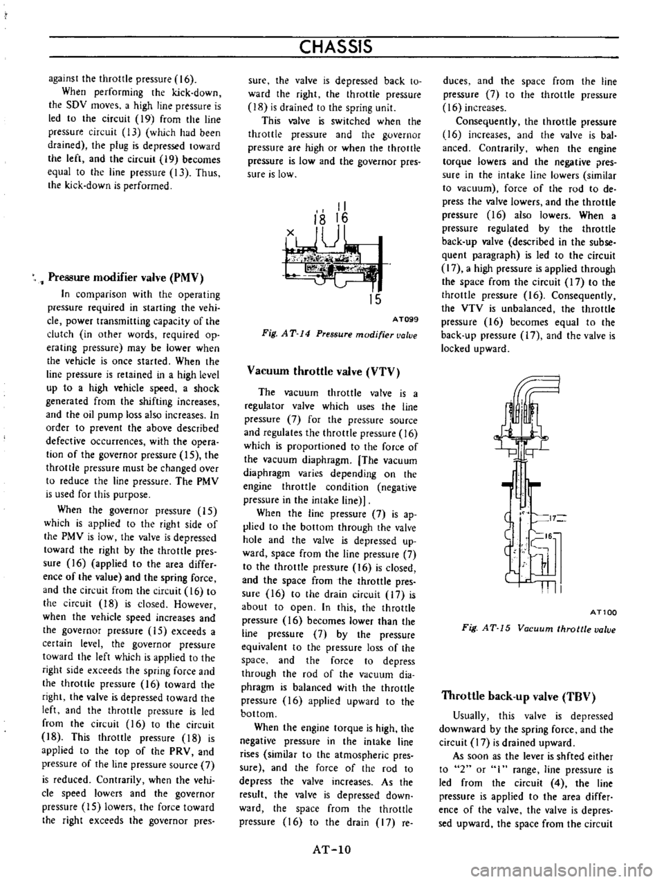
II
18
16
1JU
k
I
15
AT099
Fig
AT
14
Pressure
modifier
valve
Vacuum
throttle
valve
VTV
The
vacuum
throttle
valve
is
a
regulator
valve
which
uses
the
line
pressure
7
for
the
pressure
source
and
regulates
the
throttle
pressure
16
which
is
proportioned
to
the
force
of
the
vacuum
diaphragm
The
vacuum
diaphragm
varies
depending
on
the
engine
throttle
condition
negative
pressure
in
the
intake
line
When
the
line
pressure
7
is
ap
plied
to
the
bottom
through
the
valve
hole
and
the
valve
is
depressed
up
ward
space
from
the
line
pressure
7
to
the
throttle
pressure
16
is
closed
and
the
space
from
the
throttle
pres
sure
16
to
the
drain
circuit
17
is
about
to
open
In
this
the
throttle
pressure
16
becomes
lower
than
the
line
pressure
7
by
the
pressure
equivalent
to
the
pressure
loss
of
the
space
and
the
force
to
depress
through
the
rod
of
the
vacuum
dia
phragm
is
balanced
with
the
throttle
pressure
16
applied
upward
to
the
bottom
When
the
engine
torque
is
high
the
negative
pressure
in
the
intake
line
rises
similar
to
the
atmospheric
pres
sure
and
the
force
of
the
rod
to
depress
the
valve
increases
As
the
result
the
valve
is
depressed
down
ward
the
space
from
the
throttle
pressure
16
to
the
drain
17
re
AT
lO
duces
and
the
space
from
the
line
pressure
7
to
the
throttle
pressure
16
increases
Consequently
the
throttle
pressure
16
increases
and
the
valve
is
baI
anced
Contrarily
when
the
engine
torque
lowers
and
the
negative
pres
sure
in
the
intake
line
lowers
similar
to
vacuum
force
of
the
rod
to
de
press
the
valve
lowers
and
the
throttle
pressure
16
also
lowers
When
a
pressure
regulated
by
the
throttle
back
up
valve
described
in
the
subse
quent
paragraph
is
led
to
the
circuit
17
a
high
pressure
is
applied
through
the
space
from
the
circuit
17
to
the
throttle
pressure
16
Consequently
the
VTV
is
unbalanced
the
throttle
pressure
16
becomes
equal
to
the
back
up
ptessure
17
and
the
valve
is
locked
upward
bi
II
I
ATlOa
Fig
AT
15
Vacuum
throttle
valve
Throttle
back
up
valve
TBV
Usually
this
valve
is
depressed
downward
by
the
spring
force
and
the
circuit
17
is
drained
upward
As
soon
as
the
lever
is
shfted
either
to
2
or
range
line
pressure
is
led
from
the
circuit
4
the
line
pressure
is
applied
to
the
area
differ
ence
of
the
valve
the
valve
is
depres
sed
upward
the
space
from
the
circuit
Page 15 of 513
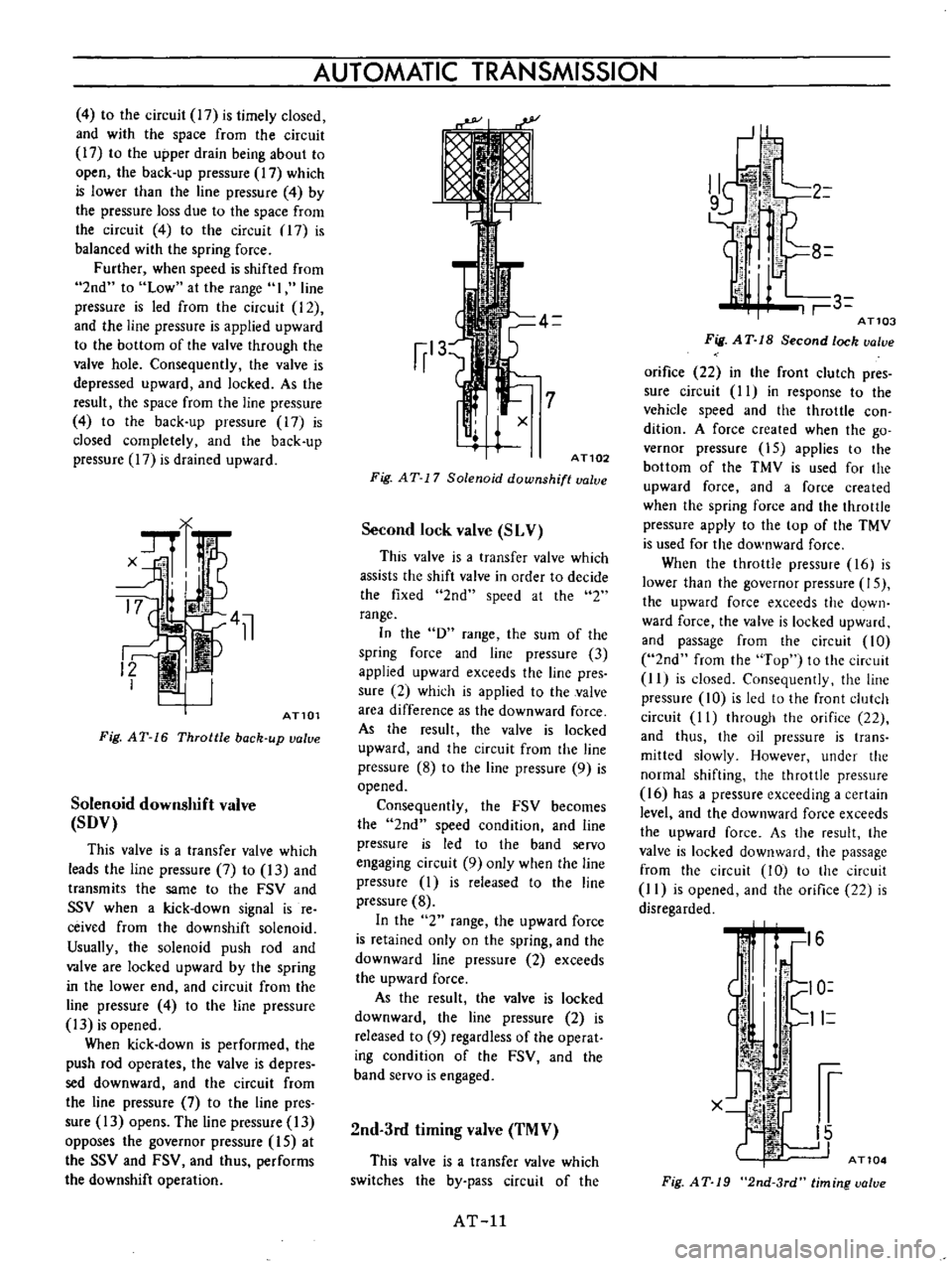
4
to
the
circuit
17
is
timely
closed
and
with
the
space
from
the
circuit
17
to
the
upper
drain
being
about
to
open
the
back
up
pressure
17
which
is
lower
than
the
line
pressure
4
by
the
pressure
loss
due
to
the
space
from
the
circuit
4
to
the
circuit
17
is
balanced
with
the
spring
force
Further
when
speed
is
shifted
from
2nd
to
Low
at
the
range
I
line
pressure
is
led
from
the
circuit
12
and
the
line
pressure
is
applied
upward
to
the
bottom
of
the
valve
through
the
valve
hole
Consequently
the
valve
is
depressed
upward
and
locked
As
the
result
the
space
from
the
line
pressure
4
to
the
back
up
pressure
17
is
closed
completely
and
the
back
up
pressure
17
is
drained
upward
AT101
Fig
AT
16
Throttle
back
up
valve
Solenoid
downshift
valve
SDV
This
valve
is
a
transfer
valve
which
leads
the
line
pressure
7
to
13
and
transmits
the
same
to
the
FSV
and
SSV
when
a
kick
down
signal
is
re
ceived
from
the
downshift
solenoid
Usually
the
solenoid
push
rod
and
valve
are
locked
upward
by
the
spring
in
the
lower
end
and
circuit
from
the
line
pressure
4
to
the
line
pressure
13
is
opened
When
kick
down
is
performed
the
push
rod
operates
the
valve
is
depres
sed
downward
and
the
circuit
from
the
line
pressure
7
to
the
line
pres
sure
13
opens
The
line
pressure
13
opposes
the
governor
pressure
15
at
the
SSV
and
FSV
and
thus
performs
the
downshift
operation
AUTOMATIC
TRANSMISSION
AT102
Fig
AT
17
Solenoid
downshift
value
Second
lock
valve
SLV
This
valve
is
a
transfer
valve
which
assists
the
shift
valve
in
order
to
decide
the
fixed
2nd
speed
at
the
2
range
In
the
D
range
the
sum
of
the
spring
force
and
line
pressure
3
applied
upward
exceeds
the
line
pres
sure
2
which
is
applied
to
the
valve
area
difference
as
the
downward
force
As
the
result
the
valve
is
locked
upward
and
the
circuit
from
the
line
pressure
8
to
the
line
pressure
9
is
opened
Consequently
the
FSV
becomes
the
2nd
speed
condition
and
line
pressure
is
led
to
the
band
servo
engaging
circuit
9
only
when
the
line
pressure
1
is
released
to
the
line
pressure
8
In
the
2
range
the
upward
force
is
retained
only
on
the
spring
and
the
downward
line
pressure
2
exceeds
the
upward
force
As
the
result
the
valve
is
locked
downward
the
line
pressure
2
is
released
to
9
regardless
of
the
operat
ing
condition
of
the
FSV
and
the
band
servo
is
engaged
2nd
3rd
timing
valve
TMV
This
valve
is
a
transfer
valve
which
switches
the
by
pass
circuit
of
the
AT
ll
J
2
3
ATl03
Fig
A
T
18
Second
lock
ualue
orifice
22
in
the
front
clutch
pres
sure
circuit
II
in
response
to
the
vehicle
speed
and
the
throttle
con
dition
A
force
created
when
the
go
vernor
pressure
15
applies
to
the
bottom
of
the
TMV
is
used
for
the
upward
force
and
a
force
created
when
the
spring
force
and
the
throttle
pressure
apply
to
the
top
of
the
TMV
is
used
for
the
downward
force
When
the
throttle
pressure
16
is
lower
than
the
governor
pressure
15
the
upward
force
exceeds
the
down
ward
force
the
valve
is
locked
upward
and
passage
from
the
circuit
10
2nd
from
the
Top
to
the
circuit
II
is
closed
Consequently
the
line
pressure
10
is
led
to
the
front
clutch
circuit
1
I
through
the
orifice
22
and
thus
the
oil
pressure
is
trans
mitted
slowly
However
under
the
normal
shifting
the
throttle
pressure
16
has
a
pressure
exceeding
a
certain
level
and
the
downward
force
exceeds
the
upward
force
As
the
result
the
valve
is
locked
downward
the
passage
from
the
circuit
10
to
the
circuit
1
I
is
opened
and
the
orifice
22
is
disregarded
1
i
16
I
O
11
l1
1
r
X
lp
I
15
J
AT104
Fig
AT
19
2nd
3rd
timing
ualue
Page 17 of 513
AUTOMATIC
TRANSMISSION
HYDRAULIC
SYSTEM
AND
MECHANICAL
OPERATION
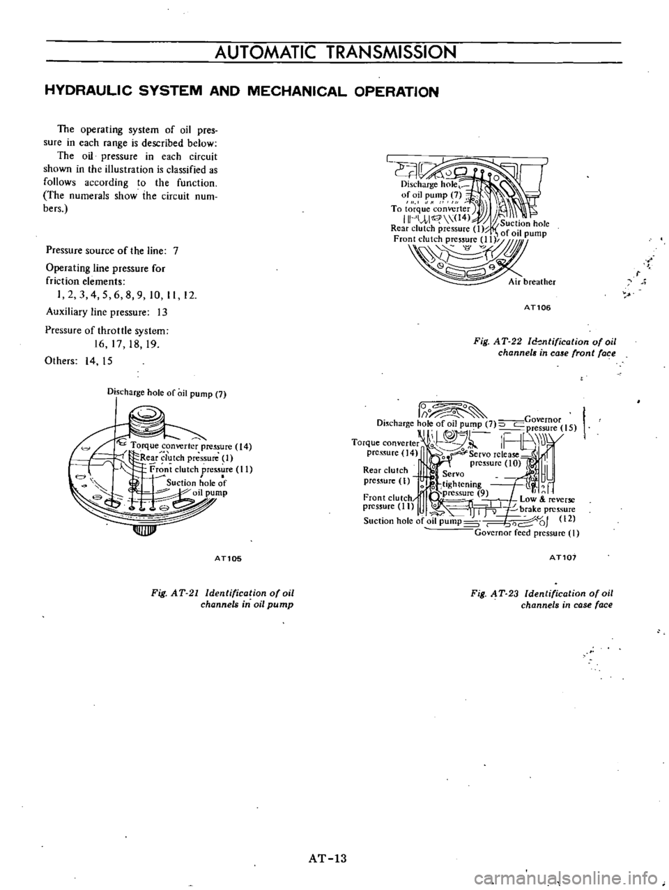
The
operating
system
of
oil
pres
sure
in
each
range
is
described
below
The
oil
pressure
in
each
circuit
shown
in
the
illustration
is
classified
as
follows
according
to
the
function
The
numerals
show
the
circuit
num
bers
Pressure
source
of
the
line
7
Operating
line
pressure
for
friction
elements
I
2
3
4
5
6
8
9
10
II
12
Auxiliary
line
pressure
13
Pressure
of
throttle
system
16
17
18
19
Others
14
15
t
AT106
Fig
AT
22
ld
Jltification
of
oil
channels
in
case
front
fac
e
Discharge
hole
of
oil
pump
7
Torque
c
nver
pre
ure
14
co
t
Re
r
lutch
pressure
l
Front
clutch
pres5ure
II
I
c
Suction
hole
of
t
o
ump
lUlJJl
0
o
f
Governor
Dl5charge
hol
of
011
pUf
lP
7
pressure
15
I
II
nl
1F
Jl
r
Torque
converter
o
L
U
pres
ure
14
It
0
Servo
release
i
I
prc
sUre
IO
Rear
clutch
Servo
L
i
pres
ure
I
0
6
tightening
19
iressu
9
01
Front
clutch
rJj
low
reverse
pressure
II
0
C
lrv
brake
pressure
Suction
hole
of
oil
pump
s
6od
OJ
12
Governor
feed
pressure
I
ATlOS
AT101
Fig
AT
21
Identification
of
oil
channels
in
oil
pu
mp
Fig
AT
23
Identification
of
oil
channels
in
case
face
AT
13