overheating DATSUN B110 1973 Service Repair Manual
[x] Cancel search | Manufacturer: DATSUN, Model Year: 1973, Model line: B110, Model: DATSUN B110 1973Pages: 513, PDF Size: 28.74 MB
Page 135 of 513

BRAKE
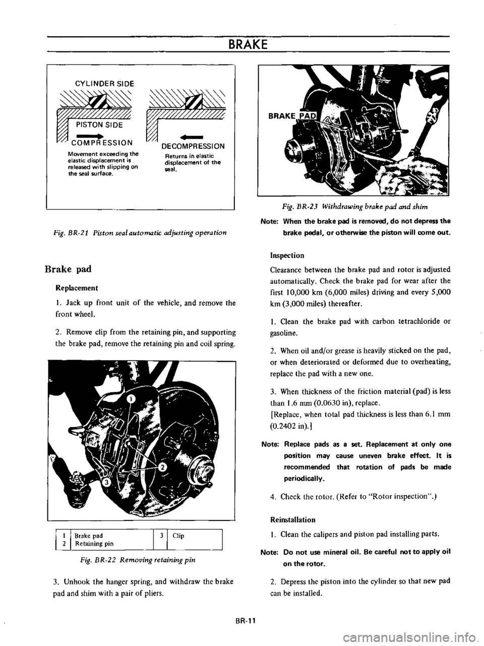
CYLINDER
SIDE
PISTON
SIDE
COMPR
ESSION
DECOMPRESSION
Movement
exceeding
the
elastic
displacement
is
released
with
slipping
on
the
seal
surface
Returns
in
elastic
displacement
of
the
seal
Fig
BR
21
Piston
seal
automatic
adjusting
operation
Brake
pad
Replacement
1
Jack
up
front
unit
of
the
vehicle
and
remove
lhe
front
wheeL
2
Remove
clip
from
the
retaining
pin
and
supporting
the
brake
pad
remove
the
retaining
pin
and
coil
spring
I
I
Brake
pad
2
Retaining
pin
I
31
Clip
Fig
BR
22
Removing
retaining
pin
3
Unhook
the
hanger
spring
and
withdraw
the
brake
pad
and
shim
with
a
pair
of
pliers
BR
ll
Fig
HR
2
Withdrawing
brake
pad
and
shim
Note
When
the
brake
pad
is
removed
do
not
depress
the
brake
pedal
or
otherwise
the
piston
will
come
out
Inspection
Clearance
between
the
brake
pad
and
rotor
is
adjusted
automatically
Check
the
brake
pad
for
wear
after
the
first
10
000
km
6
000
miles
driving
and
every
5
000
km
3
000
miles
thereafter
1
Clean
the
brake
pad
with
carbon
tetrachloride
or
gasoline
2
When
oil
and
or
grease
is
heavily
sticked
on
the
pad
or
when
deteriorated
or
deformed
due
to
overheating
replace
the
pad
with
a
new
one
3
When
thickness
of
the
friction
material
pad
is
less
than
1
6
mm
0
0630
in
replace
Replace
when
total
pad
thickness
is
less
than
6
1
mm
0
2402
in
Note
Replace
pads
as
a
set
Replacement
at
only
one
position
may
cause
uneven
brake
effect
It
is
recommended
that
rotation
of
pads
be
made
periodically
4
Check
the
rotor
Refer
to
Rotor
inspection
Reinstallation
1
Clean
the
calipers
and
piston
pad
installing
parts
Note
Do
not
use
mineral
oil
Be
careful
not
to
apply
oil
on
the
rotor
2
Depress
the
piston
into
the
cylinder
so
that
new
pad
can
be
installed
Page 335 of 513

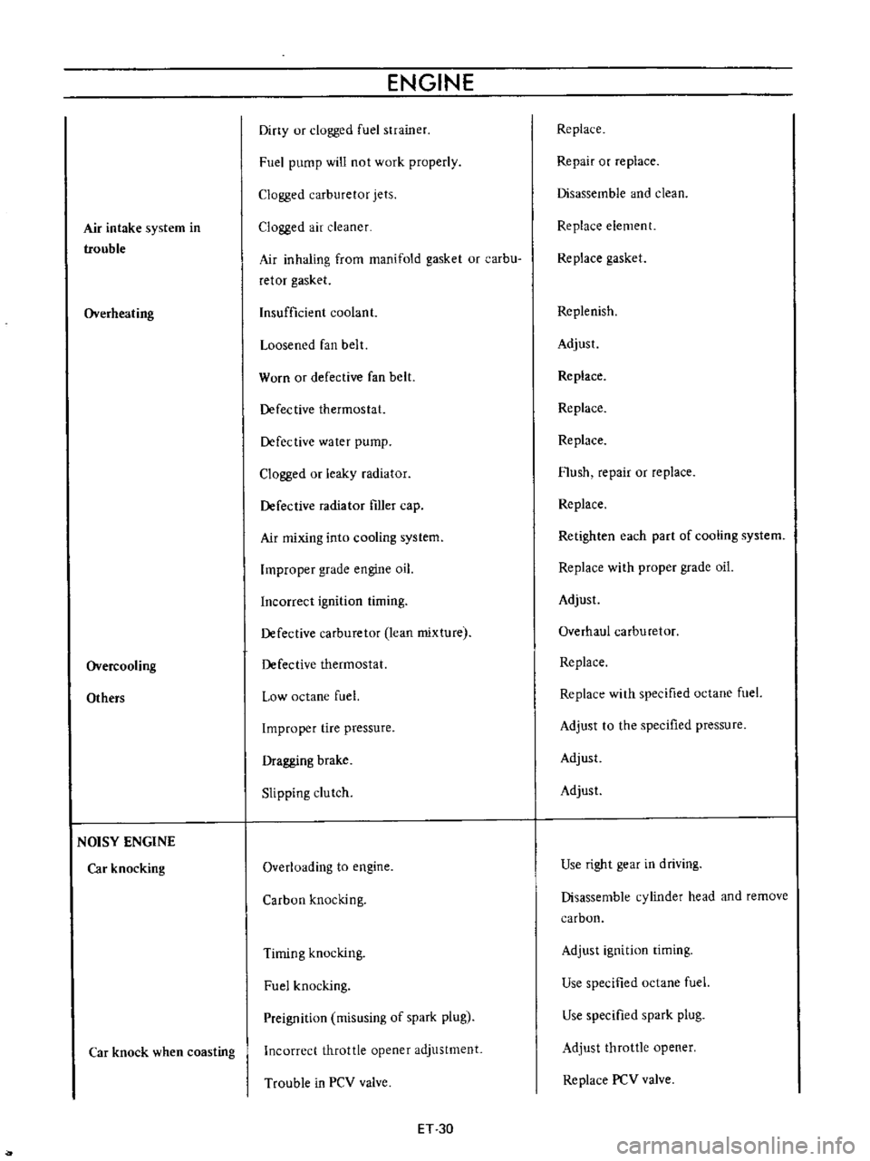
Air
intake
system
in
trouble
Overheating
Overcooling
Others
NOISY
ENGINE
Car
knocking
Car
knock
when
coasting
ENGINE
Diny
ur
clogged
fuel
strainer
Fuel
pump
will
not
work
properly
Clogged
carburetor
jets
Clogged
air
cleaner
Air
inhaling
from
manifold
gasket
or
carbu
retor
gasket
Insufficient
coolant
Loosened
fan
belt
Worn
or
defective
fan
belt
Defective
thermostat
Defective
water
pump
Clogged
or
leaky
radiator
Defective
radiator
filler
cap
Air
mixing
into
cooling
system
Improper
grade
engine
oil
Incorrect
ignition
timing
Defective
carburetor
lean
mixture
Defective
thermostat
Low
octane
fuel
Improper
tire
pressure
Dragging
brake
Slipping
clutch
Overloading
to
engine
Carbon
knocking
Timing
knocking
Fuel
knocking
Preignition
misusing
of
spark
plug
Incorrect
throttle
opener
adjustment
Trouble
in
PCV
valve
ET
30
Replace
Repair
or
replace
Disassemble
and
clean
Replace
element
Replace
gasket
Replenish
Adjust
Replace
Replace
Replace
Flush
repair
or
replace
Replace
Retighten
each
part
of
cooling
system
Replace
with
proper
grade
oil
Adjust
Overhaul
carburetor
Replace
Replace
with
specified
octane
fuel
Adjust
to
the
specified
pressure
Adjust
Adjust
Use
right
gear
in
driving
Disassemble
cylinder
head
and
remove
carbon
Adjust
ignition
timing
Use
specified
octane
fuel
Use
specified
spark
plug
Adjust
throttle
opener
Replace
PCV
valve
Page 457 of 513

ENGINE
ElECTRICAL
SYSTEM
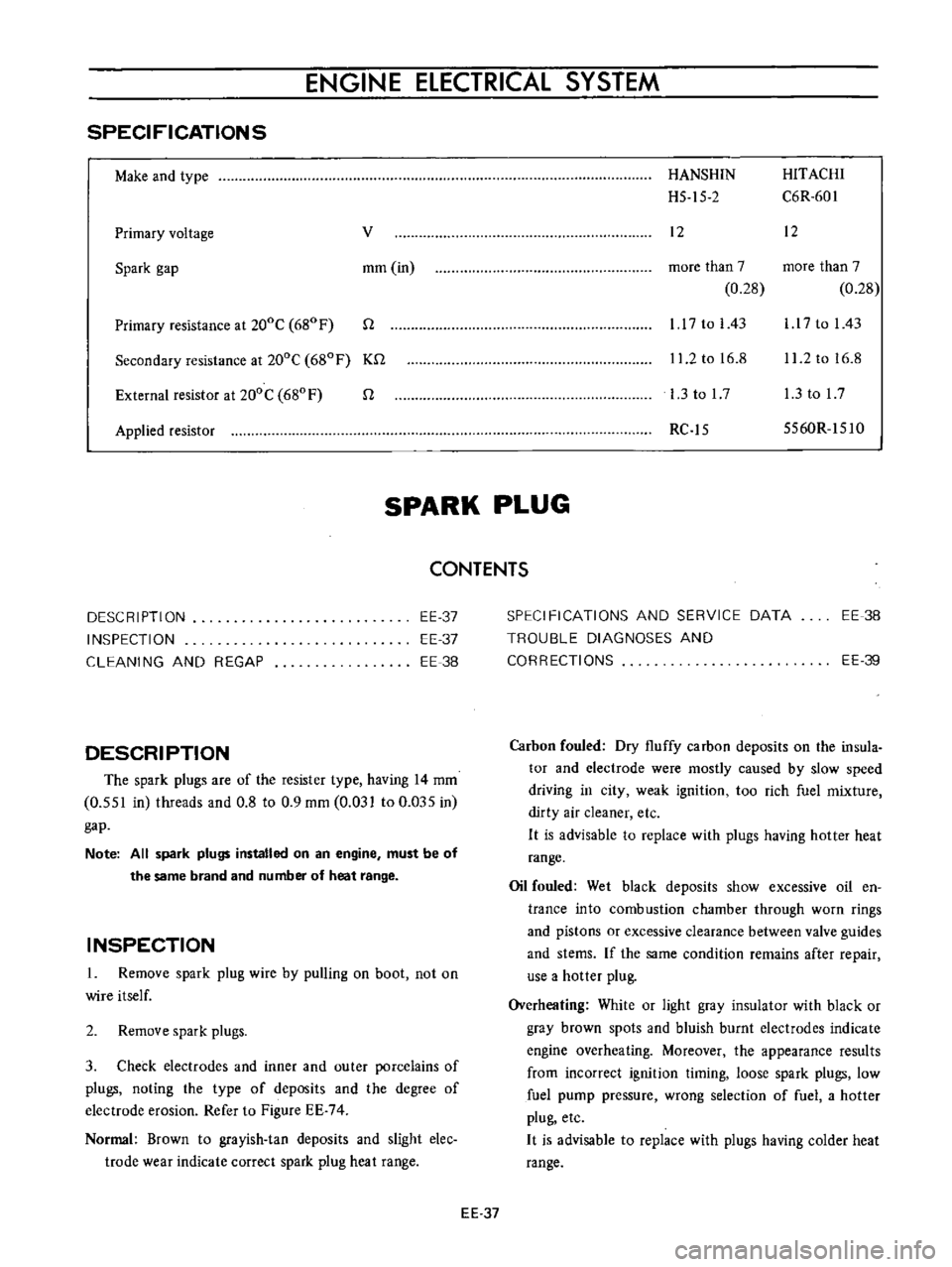
SPECIFICATIONS
Make
and
type
Primary
voltage
v
Spark
gap
mm
in
Primary
resistance
at
200C
680
F
n
Secondary
resistance
at
200C
680F
Kn
External
resistor
at
200C
680
F
n
Applied
resistor
HANSHIN
HITACHI
H5
15
2
C6R
601
12
12
more
than
7
more
than
7
0
28
0
28
1
17
to
I
43
l
l
7
to
I
43
11
2
to
16
8
11
2
to
16
8
l
3tol7
l
3tol7
RC
15
5560R
151O
SPARK
PLUG
CONTENTS
DESCRIPTION
INSPECTION
CLEANING
AND
REGAP
EE
37
EE
37
EE
38
DESCRIPTION
The
spark
plugs
are
of
the
resister
type
having
14
mm
0
551
in
threads
and
0
8
to
0
9
mm
0
031
to
0
Q35
in
gap
Note
All
spark
plugs
installed
on
an
engine
must
be
of
the
same
brand
and
number
of
heat
range
INSPECTION
1
Remove
spark
plug
wire
by
pulling
on
boot
not
on
wire
itself
2
Remove
spark
plugs
3
Check
electrodes
and
inner
and
outer
porcelains
of
plugs
noting
the
type
of
deposits
and
the
degree
of
electrode
erosion
Refer
to
Figure
EE
74
Normal
Brown
to
grayish
tan
deposits
and
slight
elec
trode
wear
indicate
correct
spark
plug
heat
range
SPECIFICATIONS
AND
SERVICE
DATA
TROUBLE
DIAGNOSES
AND
CORRECTIONS
EE
38
EE
39
Carbon
fouled
Dry
fluffy
carbon
deposits
on
the
insula
tor
and
electrode
were
mostly
caused
by
slow
speed
driving
in
city
weak
ignition
too
rich
fuel
mixture
dirty
air
cleaner
etc
H
is
advisable
to
replace
with
plugs
having
hotter
heat
range
Oil
fouled
Wet
black
deposits
show
excessive
oil
en
trance
into
combustion
chamber
through
worn
rings
and
pistons
or
excessive
clearance
between
valve
guides
and
stems
If
the
same
condition
remains
after
repair
use
a
hotter
plug
Overheating
White
or
light
gray
insulator
with
black
or
gray
brown
spots
and
bluish
burnt
electrodes
indicate
engine
overheating
Moreover
the
appearance
results
from
incorrect
ignition
timing
loose
spark
plugs
low
fuel
pump
pressure
wrong
selection
of
fuel
a
hotter
plug
etc
H
is
advisable
to
replace
with
plugs
having
colder
heat
range
EE
37
Page 458 of 513

ENGINE
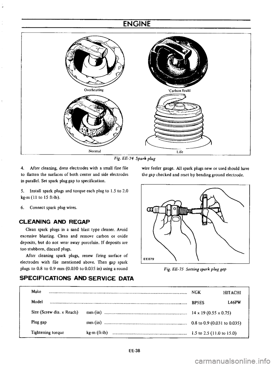
Overheating
Normal
Carbon
fould
Fig
EE
74
SpaTk
plug
Life
4
After
cleaning
dress
electrodes
with
a
small
fine
fIle
to
flatten
the
surfaces
of
both
center
and
side
electrodes
in
parallel
Set
spark
plug
gap
to
specification
5
Install
spark
plugs
and
torque
each
plug
to
1
5
to
2
0
kg
m
ll
to
15
ft
lb
6
Connect
spark
plug
wires
CLEANING
AND
REGAP
Clean
spark
plugs
in
a
sand
blast
type
cleaner
Avoid
excessive
blasting
Clean
and
remove
carbon
or
oxide
deposits
but
do
not
wear
away
porcelain
If
deposits
are
too
stubborn
discard
plugs
Mter
cleaning
spark
plugs
renew
firing
surface
of
electrodes
with
me
mentioned
above
Then
gap
spark
plugs
to
0
8
to
0
9
mm
0
030
to
0
035
in
using
a
round
SPECIFICATIONS
AND
SERVICE
DATA
Make
Model
Size
Screw
dia
x
Reach
mm
in
Plug
gap
mm
in
Tightening
torque
kg
m
ft
b
EE
38
wire
feeler
gauge
All
spark
plugs
new
or
used
should
have
the
gap
checked
and
reset
by
bending
ground
electrode
Fig
EE
75
Setting
spaTk
plug
gap
NGK
HITACHI
BP5ES
1A6PW
14
x
19
0
55
x
0
75
0
8
to
0
9
0
031
to
0
035
1
5
to
2
5
11
0
to
15
0