radio DATSUN B110 1973 Service Repair Manual
[x] Cancel search | Manufacturer: DATSUN, Model Year: 1973, Model line: B110, Model: DATSUN B110 1973Pages: 513, PDF Size: 28.74 MB
Page 232 of 513
BODY
INSTRUMENT
PANEL
CONTENTS
REMOVAL
BF
42
REMOVAL
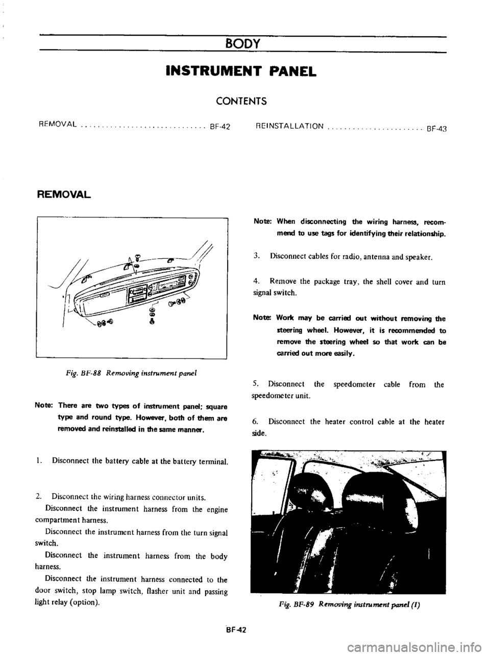
Fig
BF
88
Removing
instrument
panel
Note
There
are
two
types
of
instrument
panel
square
type
and
round
type
However
both
of
them
are
removed
and
reinstalled
in
the
same
manner
Disconnect
the
battery
cable
at
the
battery
terminal
2
Disconnect
the
wiring
harness
connector
units
Disconnect
the
instrument
harness
from
the
engine
compartment
harness
Disconnect
the
instrument
harness
from
the
turn
signal
switch
Disconnect
the
instrument
harness
frorn
the
body
harness
Disconnect
the
instrumen
t
harness
connected
to
the
door
switch
stop
lamp
switch
flasher
unit
and
passing
light
relay
option
REINSTALLATION
BF
43
Note
When
disconnecting
the
wiring
harness
recom
mend
to
use
tags
for
identifying
their
relationship
3
Disconnect
cables
for
radio
antenna
and
speaker
4
Remove
the
package
tray
the
shell
cover
and
turn
signal
switch
Note
Work
may
be
carried
out
without
removing
die
steering
wheel
However
it
is
recommended
to
remove
the
steering
wheel
50
that
work
can
be
carried
out
more
easily
5
Disconnect
the
speedometer
cable
from
the
speedometer
unit
6
Disconnect
the
heater
control
cable
at
the
heater
side
Fig
BF
89
Removing
imtrument
panel
Ii
BF
42
Page 235 of 513
DATSUN
1200
MODEL
B
11
0
SERIES
I
NISSAN
I
NISSAN
MOTOR
CO
LTD
TOKYO
JAPAN
SECTION
BE
BODY
ELECTRICAL
WIRING
FUSE
LIGHTING
SYSTEM
HORN
METERS
AND
GAUGES
WINDSHIELD
WIPER
AND
WASHER
IGNITION
SWITCH
AND
STEERING
LOCK
CLOCK
RADIO
HEATER
BE
1
BE
6
BE
7
BE
15
BE
18
BE
26
BE
29
BE
31
BE
32
BE
34
Page 253 of 513
BODY
METERS
AND
GAUGES
CONTENTS
CLUSTER
LID
Oescri
ption
Removal
SPEEDOMETER
Replacement
FUEL
GAUGE
AND
TEMPERATURE
GAUGE
Description
Replacement
BE
1B
BE
18
BE
18
BE
19
BE
19
BE
19
BE
19
BE
20
CLUSTER
LID
Description
The
cluster
lid
holds
various
rneters
indicators
and
clock
located
around
the
speedorneter
Printed
circuit
board
is
used
at
the
back
of
the
meter
as
shown
in
Figure
BE
38
and
the
printed
circuit
board
is
connected
with
multiple
connectors
Thus
the
meters
Can
be
inspected
and
serviced
extremely
easily
Except
for
the
speed
ometer
all
rneters
are
operated
electrically
The
fuel
gauge
and
therrnometer
are
very
reliable
and
they
are
equipped
with
bimetal
devices
F
a
o
ill
I
1
a
a
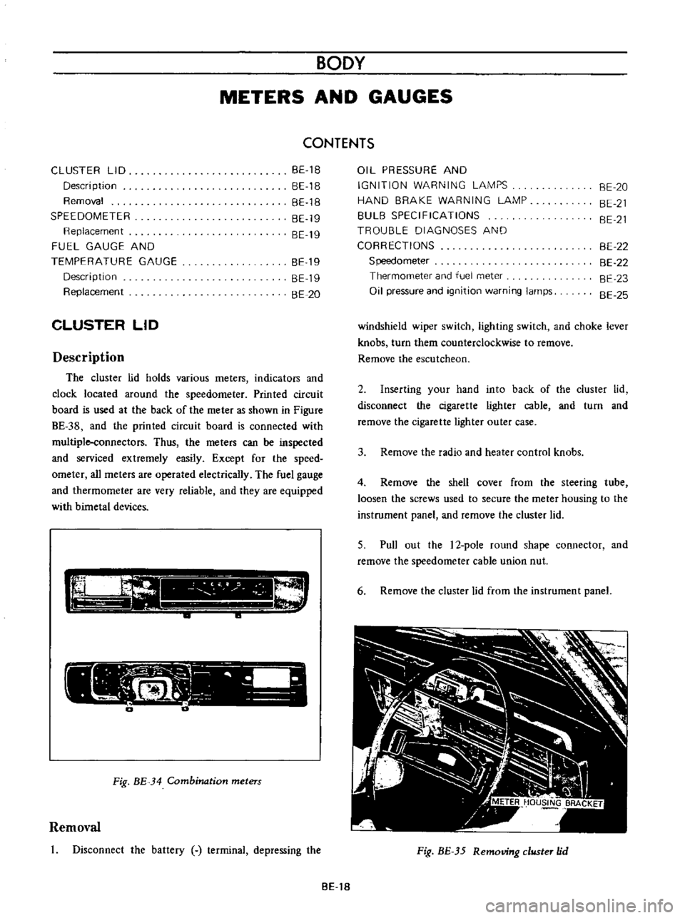
Fig
BE
34
Combination
meters
Removal
Disconnect
the
battery
terminal
depressing
the
OIL
PRESSURE
AND
IGNITION
WARNING
LAMPS
HAND
BRAKE
WARNING
LAMP
BULB
SPECIFICATIONS
TROUBLE
DIAGNOSES
AND
CORRECTIONS
Speedometer
Thermometer
and
fuel
meter
Oil
pressure
and
ignition
warning
lamps
BE
20
BE
21
BE
21
BE
22
BE
22
BE
23
BE
25
windshield
wiper
switch
lighting
switch
and
choke
lever
knobs
turn
them
counterclockwise
to
remove
Remove
the
escutcheon
2
Inserting
your
hand
into
back
of
the
cluster
lid
disconnect
the
cigarette
lighter
cable
and
turn
and
remove
the
cigarette
lighter
outer
case
3
Remove
the
radio
and
heater
control
knobs
4
Remove
the
shell
cover
from
the
steering
tube
loosen
the
screws
used
to
secure
the
meter
housing
to
the
instrument
panel
and
remove
the
cluster
lid
5
Pull
out
the
l2
pole
round
shape
connector
and
remove
the
speedometer
cable
union
nut
6
Remove
the
cluster
lid
from
the
instrument
panel
Fig
BE
35
Removing
clllSter
jd
BE
18
Page 267 of 513
BODY
RADIO
Removal
Remove
he
cluster
lid
2
Disconnect
the
lead
wires
from
the
radio
3
Remove
two
nuts
used
to
install
the
front
side
of
the
radio
on
the
instrument
panel
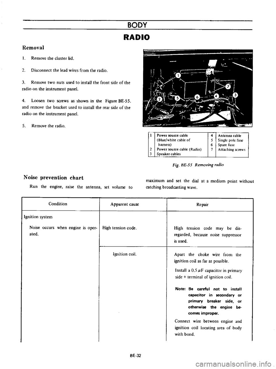
4
Loosen
two
screws
as
shown
in
the
Figure
BE
55
and
remove
the
bracket
used
to
install
the
rear
side
of
the
radio
on
the
instrument
panel
5
Remove
the
radio
Noise
prevention
chart
Run
the
engine
raise
the
antenna
set
volume
to
Condition
Apparent
cause
Ignition
system
Noise
occurs
when
engine
is
oper
High
tension
code
ated
Ignition
coil
i
O
i
M
1
iiJ
1
7
L
l
o
f
I
ft
V
r
1
1
v
I
I
t
i
J
iL
1
Power
soutee
cable
Blue
white
cable
of
harness
2
Power
source
cable
Radio
3
Speaker
cables
4
Antenna
cable
5
Single
pole
fuse
6
Spare
fuse
7
Attaching
screws
Fig
BE
55
Removing
radio
maximum
and
set
the
dial
at
a
medium
point
without
catching
broadcasting
wave
Repair
High
tension
code
may
be
dis
regarded
because
noise
suppressor
is
used
Apart
the
choke
wire
frorn
the
ignition
coil
as
far
as
possible
Install
a
0
5
uF
capacitor
in
primary
side
terminal
of
ignition
coil
Note
8e
careful
not
to
install
capacitor
in
secondary
or
primary
breaker
side
or
otherwise
the
engine
be
comes
improper
Connect
wire
between
engine
and
ignition
coil
locating
area
of
body
with
bond
BE
32
Page 444 of 513
ENGINE
MEASUREMENT
OF
REGULATING
VOLTAGE
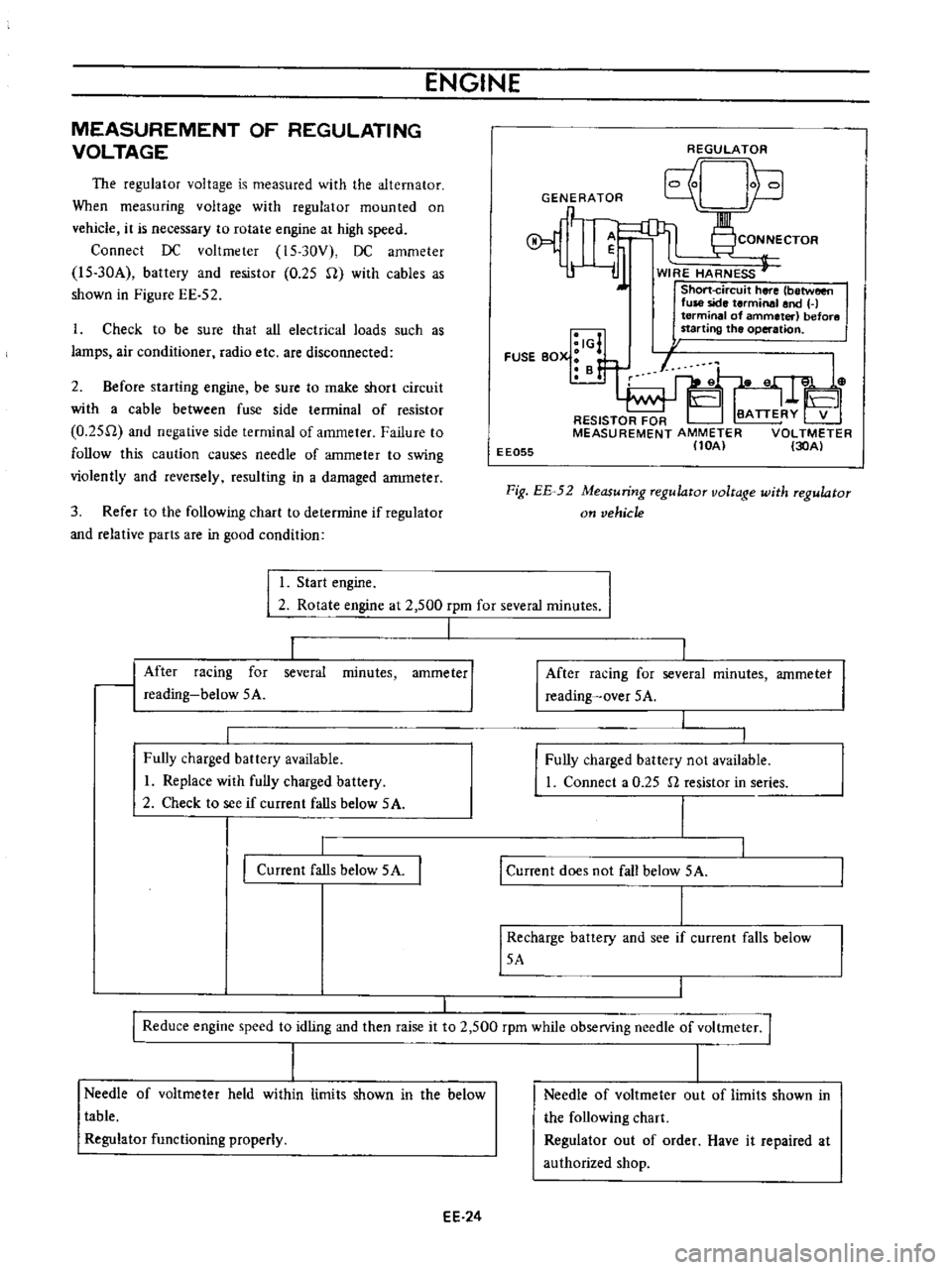
The
regulator
voltage
is
measured
with
the
alternator
When
measuring
voltage
with
regulator
mounted
on
vehicle
it
is
necessary
to
rotate
engine
at
high
speed
Connect
DC
voltmeter
15
30V
DC
ammeter
l5
30A
battery
and
resistor
0
25
U
with
cables
as
shown
in
Figure
EE
52
1
Check
to
be
sure
that
all
electrical
loads
such
as
lamps
air
conditioner
radio
etc
are
disconnected
2
Before
starting
engine
be
sure
to
make
short
circuit
with
a
cable
between
fuse
side
terminal
of
resistor
O
25U
and
negative
sIde
terminal
of
ammeter
Failure
to
follow
this
caution
causes
needle
of
ammeter
to
swing
violently
and
rever
ely
resulting
in
a
damaged
anuneter
3
Refer
to
the
following
chart
to
determine
if
regulator
and
relative
parts
are
in
good
condition
REGULATOR
Unh
GENERATOR
q
P
1
CONNECTOR
r
l
ij
WIRE
HARNESS
J
Short
circuit
here
between
fuse
side
terminal
and
H
terminal
of
ammeter
before
starting
the
operation
I
I
I
IG
FUSE
BOX
B
f
EE055
Fig
EE
52
Measuring
regulator
voltage
with
regulator
on
vehicle
I
Start
engine
I
2
Rotate
engine
at
2
500
rpm
for
several
minutes
I
1
minutes
ammeter
I
After
racing
for
reading
below
5A
several
Fully
charged
battery
available
I
Replace
with
fully
charged
battery
2
Check
to
see
if
current
falls
below
5A
Current
falls
below
5A
I
After
racing
for
several
reading
over
5A
minutes
ammetet
I
Fully
charged
battery
not
available
1
Connect
a
0
25
n
resistor
in
series
I
Current
does
not
fall
below
5A
I
Recharge
battery
and
see
if
current
falls
below
5A
I
I
Reduce
engine
speed
to
idling
and
then
raise
it
to
2
500
rpm
while
observing
needle
of
voltmeter
I
I
I
Needle
of
voltmeter
held
within
limits
shown
in
the
below
table
Regulator
functioning
properly
EE
24
Needle
of
voltmeter
out
of
limits
shown
in
the
following
chart
Regulator
out
of
order
Have
it
repaired
at
authorized
shop