steering wheel adjustment DATSUN B110 1973 Service Repair Manual
[x] Cancel search | Manufacturer: DATSUN, Model Year: 1973, Model line: B110, Model: DATSUN B110 1973Pages: 513, PDF Size: 28.74 MB
Page 107 of 513
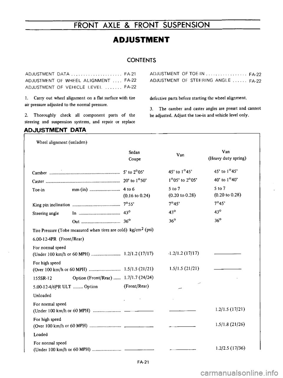
FRONT
AXLE
FRONT
SUSPENSION
ADJUSTMENT
CONTENTS
ADJUSTMENT
DATA
ADJUSTMENT
OF
WHEEL
ALIGNMENT
ADJUSTMENT
OF
VEHICLE
LEVEL
FA
21
FA
22
FA
22
1
Carry
out
wheel
alignment
on
a
flat
surface
with
tire
air
pressure
adjusted
to
the
normal
pressure
2
Thoroughly
check
all
component
parts
of
the
steering
and
suspension
systems
and
repair
or
replace
AD
JUSTMENT
DATA
I
Wheel
alignment
unladen
Sedan
Coupe
Camber
5
to
2005
Caster
20
to
1050
Toe
in
mm
in
4
to
6
0
16
to
0
24
King
pin
inclination
7055
Steering
angle
In
430
Out
360
Tire
Pressure
Tobe
measured
when
tires
are
cold
kgfcm2
psi
6
00
12
4PR
Front
Rear
For
normal
speed
Under
100
km
h
or
60
MPH
For
high
speed
Over
100
km
h
or
60
MPH
15SSR
12
Option
Front
Rear
1
2
1
2
17
17
1
5
1
5
21
21
I
7
I
7
24
24
Front
Rear
5
00
12
4
6
R
ULT
Unloaded
Option
For
normal
speed
Under
100
km
h
or
60
MPH
For
high
speed
Over
100
km
h
or
60
MPH
Loaded
For
normal
speed
Under
100
km
h
or
60
MPH
FA
21
ADJUSTMENT
OF
TOE
IN
ADJUSTMENT
OF
STEERING
ANGLE
FA
22
FA
22
defective
parts
before
starting
the
wheel
alignment
3
The
camber
and
caster
angles
are
preset
and
cannot
be
adjusted
Adjust
the
toe
in
and
vehicle
level
only
Van
Van
Heavy
duty
spring
45
to
1045
45
to
1045
1005
to
2005
40
to
1040
5
to
7
5
to
7
0
20
to
0
28
0
20
to
0
28
7045
7045
430
430
360
360
1
2
1
2
I
7
I
7
1
5
1
5
21
21
1
2
1
5
17
21
1
5
1
8
21
26
1
2
2
5
17
36
Page 108 of 513
CHASSIS
For
high
speed
Over
100
km
h
or
60
MPH
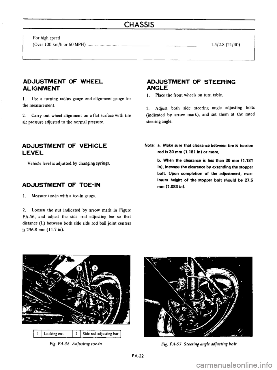
ADJUSTMENT
OF
WHEEL
ALIGNMENT
Use
a
turning
radius
gauge
and
alignment
gauge
for
the
measurement
2
Carry
out
wheel
alignment
on
a
flat
surface
with
tire
air
pressure
adjusted
to
the
normal
pressure
ADJUSTMENT
OF
VEHICLE
LEVEL
Vehicle
level
is
adjusted
by
changing
springs
ADJUSTMENT
OF
TOE
IN
Measure
toe
in
with
a
toe
in
gauge
2
Loosen
the
nut
indicated
by
arrow
mark
in
Figure
FA
56
and
adjust
the
side
rod
adjusting
bar
so
that
distance
L
between
both
side
side
rod
ball
joint
centers
is
296
8
mm
11
7
in
I
1
I
Locking
nu
t
I
2
I
Side
rod
adjusting
bar
I
Fig
FA
56
Adjusitng
toe
in
1
5
2
8
21
40
ADJUSTMENT
OF
STEERING
ANGLE
1
Place
the
front
wheels
on
turn
table
2
Adjust
both
side
steering
angle
adjusting
bolts
indicated
by
arrow
mark
and
set
them
al
the
rated
steering
angle
Note
8
Make
sure
that
clearance
between
tire
tension
rod
is
30
mm
11
181
in
or
more
b
When
the
clearance
is
less
than
30
mm
1
181
in
inaease
the
clearance
by
extending
the
stopper
bolt
Upon
completion
of
the
adjustment
max
imum
height
of
the
stopper
bolt
should
be
27
5
mm
1
083
in
Fig
FA
57
Steering
angle
adjusting
bolt
FA
22
Page 112 of 513
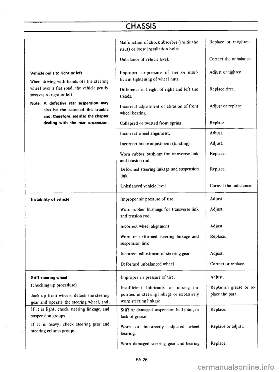
Vehicle
pulls
to
right
or
left
When
driving
with
hands
off
the
steering
wheel
over
a
flat
road
the
vehicle
gently
swerves
to
right
or
left
Note
A
defective
rear
suspension
may
also
be
the
cause
of
this
trouble
and
therefore
see
also
the
chapter
dealing
with
the
rear
suspension
Instability
of
vehicle
Stiff
steering
wheel
checking
up
procedure
Jack
up
front
wheels
detach
the
steering
gear
and
operate
the
steering
wheel
and
If
it
is
light
check
steering
linkage
and
suspension
groups
If
it
is
heavy
check
steering
gear
and
steering
colunm
groups
CHASSIS
Malfunction
of
shock
absorber
inside
the
strut
or
loose
installation
bolts
Unbalance
of
vehicle
level
Improper
air
pressure
of
tire
or
insuf
ficient
tightening
of
wheel
nuts
Difference
in
height
of
right
and
left
tire
treads
Incorrect
adjustment
or
abrasion
of
front
wheel
bearing
Collapsed
or
twisted
front
spring
Incorrect
wheel
alignment
Incorrect
brake
adjustment
binding
Worn
rubber
bushings
for
transverse
link
and
tension
rod
Deformed
steering
linkage
and
suspension
link
Unbalanced
vehicle
level
Improper
air
pressure
of
tire
Worn
rubber
bushings
for
transverse
link
and
tension
rod
Incorrect
wheel
alignment
Worn
or
deformed
steering
linkage
and
suspension
link
Incorrect
adjustment
of
steering
gear
Deformed
unbalanced
wheel
Improper
air
pressure
of
tire
Insufficient
lubricants
or
mixing
im
purities
in
steering
linkage
or
excessively
worn
steering
linkage
Stiff
or
damaged
suspension
ball
joint
or
lack
of
grease
Worn
or
incorrectly
adjusted
wheel
bearing
Worn
damaged
steering
gear
and
bearing
FA
26
Replace
or
retighten
Correct
the
unbalance
Adjust
or
tighten
Replace
tires
Adjust
or
replace
Replace
Adjust
Adjust
Replace
Replace
Correct
the
unbalance
Adjust
Adjust
Adjust
Replace
Adjust
Correct
or
replace
Adjust
Repl
nish
grease
or
re
place
the
part
Replace
Replace
or
adjust
Replace
Page 161 of 513
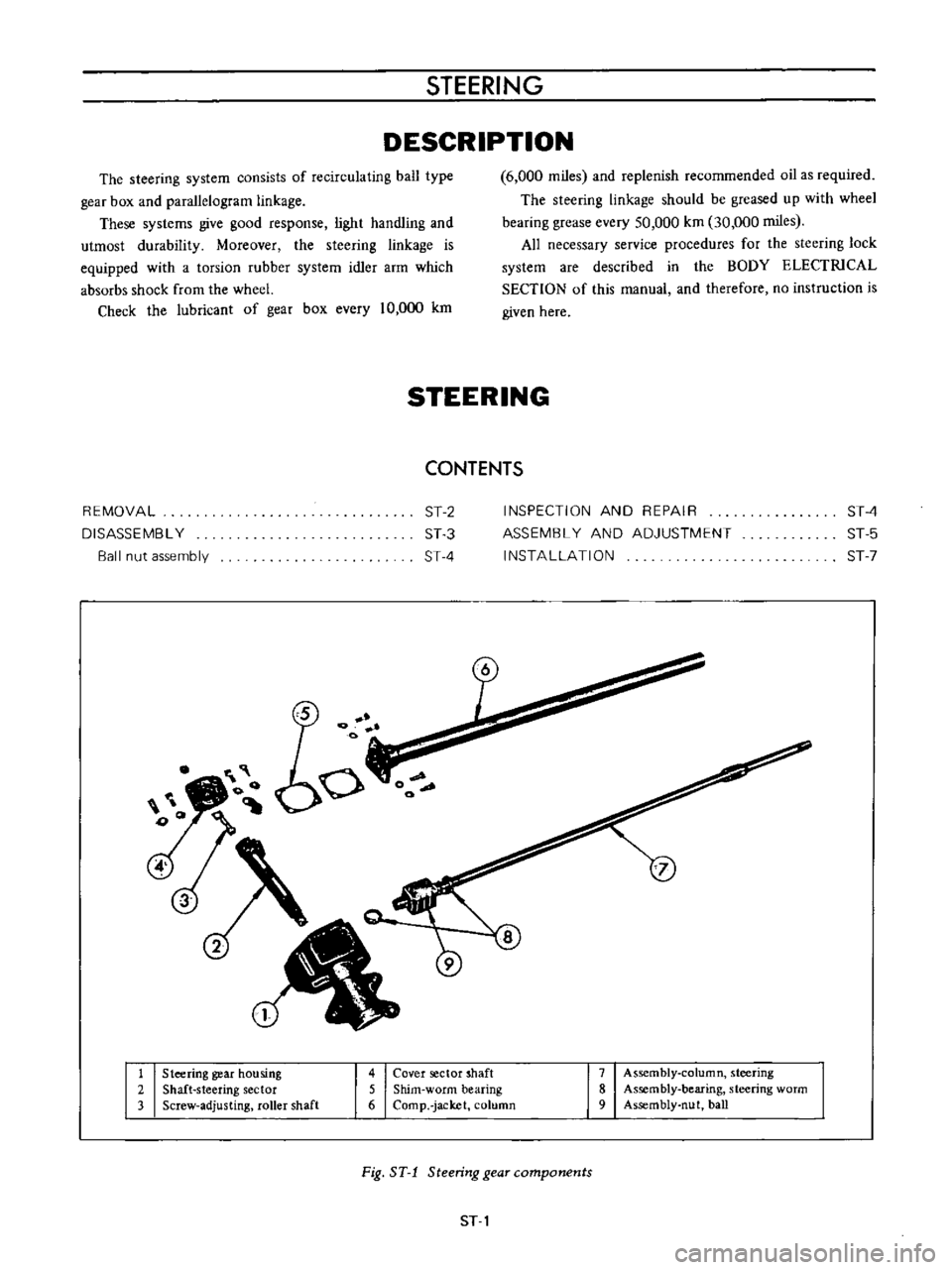
STEERING
DESCRIPTION
The
steering
system
consists
of
recirculating
ball
type
gear
box
and
parallelogram
linkage
These
systems
give
good
response
light
handling
and
utmost
durability
Moreover
the
steering
linkage
is
equipped
with
a
torsion
rubber
system
idler
arm
which
absorbs
shock
from
the
wheel
Check
the
lubricant
of
gear
box
every
10
000
km
6
000
miles
and
replenish
recommended
oil
as
required
The
steering
linkage
should
be
greased
up
with
wheel
bearing
grease
every
50
000
km
30
000
miles
All
necessary
service
procedures
for
the
steering
lock
system
are
described
in
the
BODY
ELECTRICAL
SECTION
of
this
manual
and
therefore
no
instruction
is
given
here
STEERING
CONTENTS
REMOVAL
DISASSEMBL
Y
Ball
nut
assembly
ST
2
ST
3
ST
4
INSPECTION
AND
REPAIR
ASSEMBL
Y
AND
ADJUSTMENT
INSTALLATION
ST
4
ST
5
ST
7
1
Steering
gear
housing
2
Shaft
steering
sector
3
Screw
adjusting
roller
shaft
4
Cover
sector
shaft
5
Shim
worm
bearing
6
Comp
jacket
column
7
Assembly
column
steering
8
Assembly
bearing
steering
worm
9
Assembly
nut
ball
Fig
ST
1
Steering
gear
components
ST
1
Page 176 of 513
CHASSIS
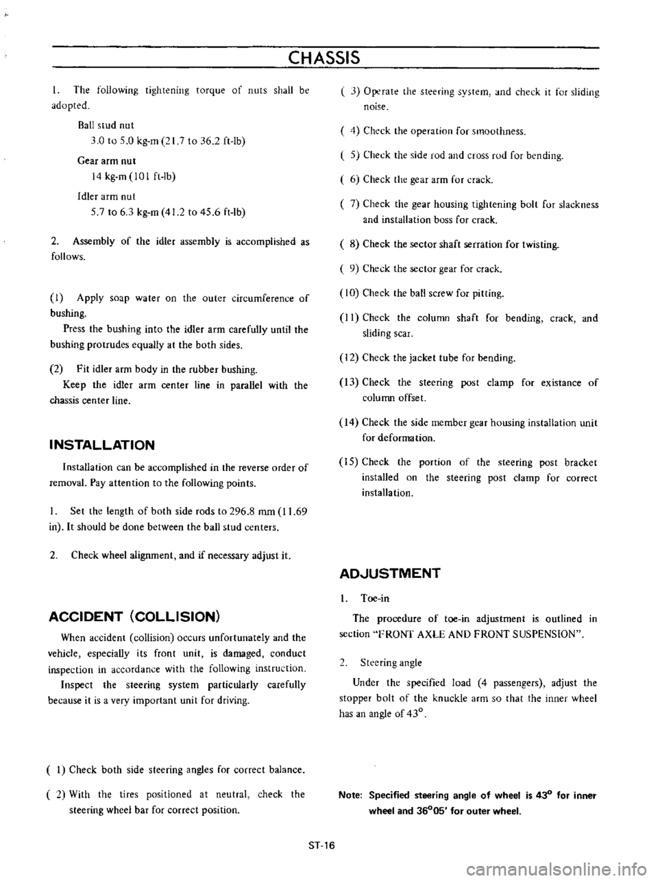
The
following
tightening
torque
of
nuts
shall
be
adopted
Ball
stud
nut
3
0
to
5
0
kg
m
21
7
to
36
2
ft
lb
Gear
arm
nut
14
kg
m
101
ft
lb
Idler
arm
nut
57
to
6
3
kg
m
41
2
to
45
6
ft
lb
2
Assembly
of
the
idler
assembly
is
accomplished
as
follows
I
Apply
soap
water
on
the
outer
circumference
of
bushing
Press
the
bushing
into
the
idler
arm
carefully
until
the
bushing
protrudes
equally
at
the
both
sides
2
Fit
idler
arm
body
in
the
rubber
bushing
Keep
the
idler
arm
center
line
in
parallel
with
the
chassis
center
line
INSTALLATION
Installation
can
be
accomplished
in
the
reverse
order
of
removal
Pay
attention
to
the
following
points
Set
the
length
of
both
side
rods
to
296
8
mm
11
69
in
It
should
be
done
between
the
ball
stud
centers
2
Check
wheel
alignment
and
if
necessary
adjust
it
ACCIDENT
COLLISION
When
accident
collision
occurs
unfortunately
and
the
vehicle
especially
its
front
unit
is
damaged
conduct
inspection
in
accordance
with
the
following
instruction
Inspect
the
steering
system
particularly
carefully
because
it
is
a
very
important
unit
for
driving
I
Check
both
side
steering
angles
for
correct
balance
2
With
the
tires
positioned
at
neutral
steering
wheel
bar
for
correct
position
check
the
l
3
Operate
the
steering
system
and
check
it
for
sliding
noise
4
Check
the
operation
for
smoothness
l
5
Check
the
side
rod
and
cross
rod
for
bending
6
Check
the
gear
arm
for
crack
7
Check
the
gear
housing
tiglltening
bolt
for
slackness
and
installation
boss
for
crack
8
Check
the
sector
shaft
serration
for
twisting
9
Check
the
sector
gear
for
crack
10
Check
the
ball
screw
for
pitting
II
Check
the
column
shaft
for
bending
crack
and
sliding
scar
12
Check
the
jacket
tube
for
bending
13
Check
the
steering
post
clamp
for
existance
of
column
offset
14
Check
the
side
member
gear
housing
installation
unit
for
deformation
IS
Check
the
portion
of
the
steering
post
bracket
installed
on
the
steering
post
clamp
for
correct
installation
AD
JUSTMENT
I
Toe
in
The
procedure
of
toe
in
adjustment
is
outlined
in
section
FRONT
AXLE
AND
FRONT
SUSPENSION
2
Steering
angle
Under
the
specified
load
4
passengers
adjust
the
stopper
bolt
of
the
knuckle
arm
so
that
the
inner
wheel
has
an
angle
of
430
Note
Specified
steering
angle
of
wheel
is
430
for
inner
wheel
and
36005
for
outer
wheel
ST
16
Page 178 of 513
CHASSIS
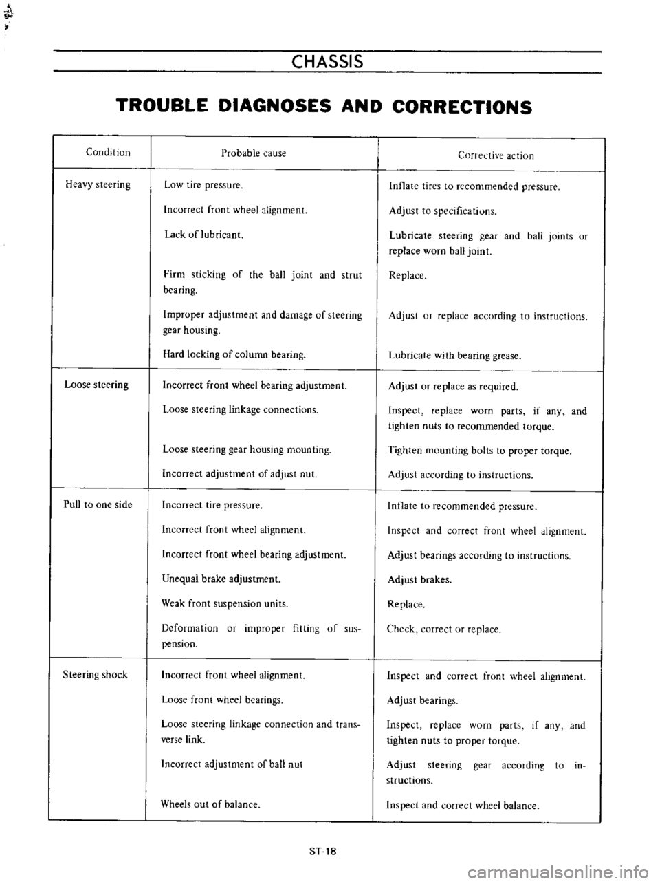
TROUBLE
DIAGNOSES
AND
CORRECTIONS
Condition
Heavy
steering
Loose
steering
PuU
to
one
side
Steering
shock
Probable
cause
Low
tire
pressure
Incorrect
front
wheel
alignment
Lack
of
lubricant
Firm
sticking
of
the
ball
joint
and
strut
bearing
Improper
adjustment
and
damage
of
steering
gear
housing
Hard
locking
of
column
bearing
Incorrect
front
wheel
bearing
adjustment
Loose
steering
linkage
connections
Loose
steering
gear
housing
mounting
Incorrect
adjustment
of
adjust
nut
Incorrect
tire
pressure
Incorrect
front
wheel
alignment
Incorrect
front
wheel
bearing
adjustment
Unequal
brake
adjustment
Weak
front
suspension
units
Deformation
or
improper
fitting
of
sus
pension
Incorrect
front
wheel
alignment
Loose
front
wheel
bearings
Loose
steering
linkage
connection
and
trans
verse
link
Incorrect
adjustment
of
ball
nut
Wheels
out
of
balance
ST
18
Corrective
action
Inflate
tires
to
recommended
pressure
Adjust
to
specifications
Lubricate
steering
gear
and
ball
joints
or
replace
worn
ball
joint
Replace
Adjust
or
replace
according
to
instructions
Lubricate
with
bearing
grease
Adjust
or
replace
as
required
Inspect
replace
worn
parts
if
any
and
tighten
nuts
to
recommended
torque
Tighten
mounting
bolts
to
proper
torque
Adjust
according
to
instructions
Inflate
to
recommended
pressure
Inspect
and
correct
front
wheel
alignment
Adjust
bearings
according
to
instructions
Adjust
brakes
Replace
Check
correct
or
replace
Inspect
and
correct
front
wheel
alignment
Adjust
bearings
Inspect
replace
worn
parts
if
any
and
tighten
nuts
to
proper
torque
Adjust
steering
gear
according
to
in
structions
Inspect
and
correct
wheel
balance
Page 475 of 513
CLUTCH
J
I
I
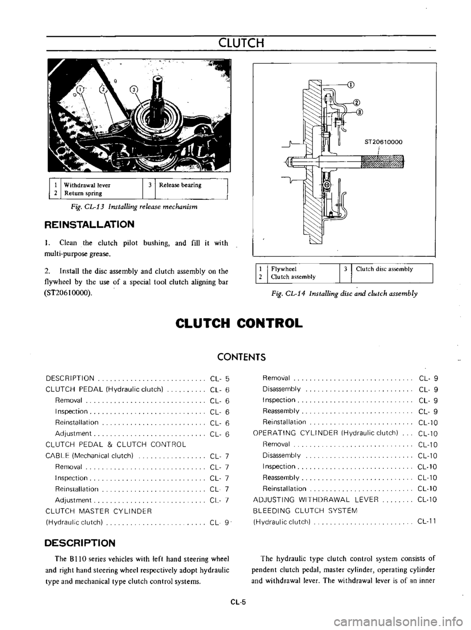
Withdrawal
lever
2
Return
spring
I
31
Release
bearing
ST20610000
iwn
rm
hj
sf
W
Fig
CL
13
Installing
release
mechanism
REINSTALLATION
L
Clean
the
clutch
pilot
bushing
and
fill
it
with
multi
purpose
grease
2
Install
the
disc
assembly
and
clutch
assembly
on
the
flywheel
by
the
use
of
a
special
tool
clutch
aligning
bar
ST206
I
0000
12
I
Flywheel
Clutch
assembly
131
Clutch
disc
assembly
Fig
CL
14
Installing
disc
and
clutch
assembly
CLUTCH
CONTROL
CONTENTS
DESCRIPTION
CL
5
Removal
CL
9
CLUTCH
PEDAL
Hydraulic
clutch
CL
6
Disassembly
CL
9
Removal
CL
6
Inspection
CL
9
Inspection
CL
6
Reassembly
CL
9
Reinstallation
CL
6
Reinstallation
CL
10
Adjustment
CL
6
OPERATING
CYLINDER
Hydraulic
clutch
CL
10
CLUTCH
PEDAL
CLUTCH
CONTROL
Removal
CL
10
CABLE
Mechanical
clutch
CL
7
Disassembly
CL
10
Removal
CL
7
Inspection
CL
10
Inspection
CL
7
Reassembly
CL
10
Reinstallation
CL
7
Reinstallation
CL
10
Adjustment
CL
7
ADJUSTING
WITHDRAWAL
LEVER
CL
10
CLUTCH
MASTER
CYLINDER
BLEEDING
CLUTCH
SYSTEM
Hydraulic
clutch
CL
9
Hydraulic
clutch
CL
11
DESCRIPTION
The
B
I
IO
series
vehicles
with
left
hand
steering
wheel
and
right
hand
steering
wheel
respectively
adopt
hydraulic
type
and
mechanical
type
clutch
control
systems
The
hydraulic
type
clutch
control
system
consists
of
pendent
clutch
pedal
master
cylinder
operating
cylinder
and
withdrawal
lever
The
withdrawal
lever
is
of
an
inner
CL
5