brake rotor DATSUN PICK-UP 1977 Service Manual
[x] Cancel search | Manufacturer: DATSUN, Model Year: 1977, Model line: PICK-UP, Model: DATSUN PICK-UP 1977Pages: 537, PDF Size: 35.48 MB
Page 23 of 537

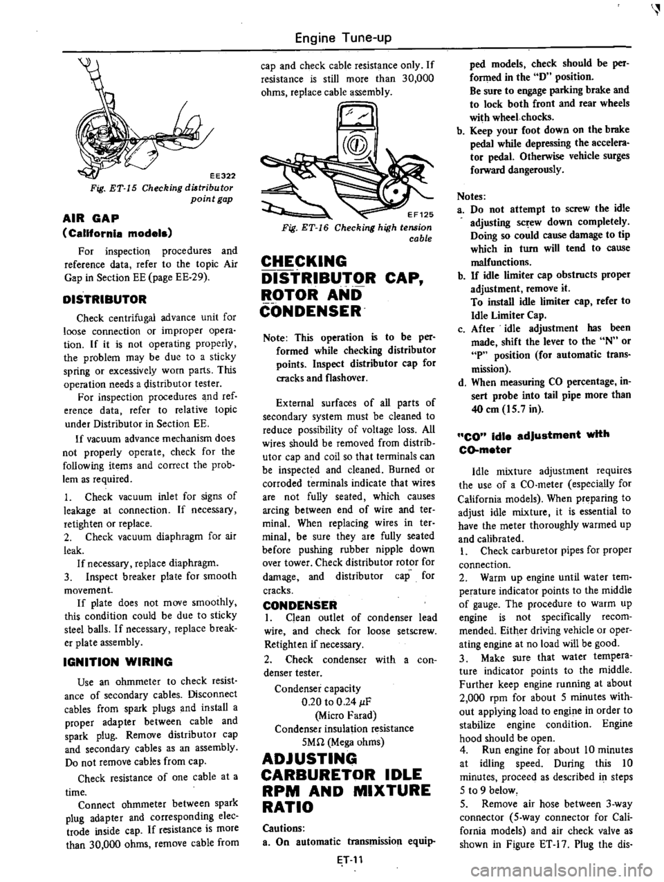
EE322
Fig
ET
15
Checking
diltribu
tor
point
gap
AIR
GAP
California
models
For
inspection
procedures
and
reference
data
refer
to
the
topic
Air
Gap
in
Section
EE
page
EE
29
DISTRIBUTOR
Check
centrifugal
advance
unit
for
loose
connection
or
improper
opera
tion
If
it
is
not
operating
properly
the
problem
may
be
due
to
a
sticky
spring
or
excessively
worn
parts
This
operation
needs
a
distributor
tester
For
inspection
procedures
and
ref
erence
data
refer
to
relative
topic
under
Distributor
in
Section
EE
If
vacuum
advance
mechanism
does
not
properly
operate
check
for
the
following
items
and
correct
the
prob
lem
as
required
1
Check
vacuum
inlet
for
signs
of
leakage
at
connection
If
necessary
retighten
or
replace
2
Check
vacuum
diaphragm
for
air
leak
If
necessary
replace
diaphragm
3
Inspect
breaker
plate
for
smooth
movement
If
plate
does
not
move
smoothly
this
condition
could
be
due
to
sticky
steel
balls
If
necessary
replace
break
er
plate
assembly
IGNITION
WIRING
Use
an
ohmmeter
to
check
resist
ance
of
secondary
cables
Disconnect
cables
from
spark
plugs
and
install
a
proper
adapter
between
cable
and
spark
plug
Remove
distributor
cap
and
secondary
cables
as
an
assembly
Do
not
remove
cables
from
cap
Check
resistance
of
one
cable
at
a
time
Connect
ohmmeter
between
spark
plug
adapter
and
corresponding
elec
trade
inside
cap
If
resistance
is
more
than
30
000
ohms
remove
cable
from
Engine
Tune
up
cap
and
check
cable
resistance
only
If
resistance
is
still
more
than
30
000
ohms
replace
cable
assembly
EF125
Checking
high
tension
cable
CHECKING
DISTRIBUTOR
CAP
ROTOR
AND
CONDENSER
Note
This
operation
is
to
be
per
formed
while
checking
distributor
points
Inspect
distributor
cap
for
cracks
and
flashover
External
surfaces
of
all
parts
of
secondary
system
must
be
cleaned
to
reduce
possibility
of
voltage
loss
All
wires
should
be
removed
from
distrib
utor
cap
and
coil
so
that
terminals
can
be
inspected
and
cleaned
Burned
or
corroded
terminals
indicate
that
wires
are
not
fully
seated
which
causes
arcing
between
end
of
wire
and
ter
minal
When
replacing
wires
in
ter
minai
be
sure
they
are
fully
seated
before
pushing
rubber
nipple
down
over
tower
Check
distributor
rotor
for
damage
and
distributor
cap
for
cracks
CONDENSER
I
Clean
outlet
of
condenser
lead
wire
and
check
for
loose
setscrew
Retighten
if
necessary
2
Check
condenser
with
a
con
denser
tester
Condenser
capacity
0
20
to
0
24
IF
Micro
Farad
Condenser
insulation
resistance
5Mn
Mega
ohms
ADJUSTING
CARBURETOR
IDLE
RPM
AND
MIXTURE
RATIO
Cautions
a
On
automatic
transmission
equip
T
11
ped
models
check
should
be
per
fonned
in
the
D
position
Be
sure
to
engage
parking
brake
and
to
lock
both
front
and
rear
wheels
with
wheel
chocks
b
Keep
your
foot
down
on
the
brake
pedal
while
depressing
the
accelera
tor
pedal
Otherwise
vehicle
surges
forward
dangerously
Notes
a
Do
not
attempt
to
screw
the
idle
adjusting
sc
ew
down
completely
Doing
so
could
cause
damage
to
tip
which
in
turn
will
tend
to
cause
malfunctions
b
If
idle
limiter
cap
obstructs
proper
adjustment
remove
it
To
install
idle
limiter
cap
refer
to
Idle
Limiter
Cap
c
After
idle
adjustment
has
been
made
shift
the
lever
to
the
N
or
P
position
for
automatic
trans
mission
d
When
measuring
CO
percentage
in
sert
probe
into
tail
pipe
more
than
40
em
15
7
in
CO
idle
adjustment
with
CD
meter
Idle
mixture
adjustment
requires
the
use
of
a
CO
meter
especially
for
California
models
When
preparing
to
adjust
idle
mixture
it
is
essential
to
have
the
meter
thoroughly
warmed
up
and
calibrated
I
Check
carburetor
pipes
for
proper
connection
2
Warm
up
engine
until
water
tem
perature
indicator
points
to
the
middle
of
gauge
The
procedure
to
warm
up
engine
is
not
specifically
recom
mended
Either
driving
vehicle
or
oper
ating
engine
at
no
load
will
be
good
3
Make
sure
that
water
tempera
ture
indicator
points
to
the
middle
Further
keep
engine
running
at
about
2
000
rpm
for
about
5
minutes
with
out
applying
load
to
engine
in
order
to
stabilize
engine
condition
Engine
hood
should
be
open
4
Run
engine
for
about
10
minutes
at
idling
speed
During
this
10
minutes
proceeq
as
described
i
steps
5
to
9
below
5
Remove
air
hose
between
3
way
connector
5
way
connector
for
Cali
fornia
models
and
air
check
valve
as
shown
in
Figure
ET
17
Plug
the
dis
Page 314 of 537

Using
the
tester
check
the
two
black
yellow
BY
wires
from
the
in
hibitor
switch
in
the
ranges
N
and
I
and
the
tw
re
d
black
RBj
wir
s
in
the
range
R
for
continuity
Turn
range
select
lever
in
both
directions
from
each
lever
set
position
and
check
each
continuity
range
It
is
normal
if
the
electricity
is
on
while
the
lever
is
within
an
angle
of
about
30
on
both
sides
from
each
lever
set
line
How
ever
if
its
continl
ity
range
is
obvious
ly
unequal
on
both
sides
adjustment
is
required
If
any
malfunction
is
found
un
screw
the
fastening
nut
of
the
range
selector
lever
and
two
fastening
bolts
of
the
switch
body
and
then
remove
the
machine
screw
under
the
switch
body
Adjust
the
manual
shaft
correct
ly
to
the
position
N
by
means
of
the
selector
lever
When
the
slot
of
the
shaft
becomes
vertical
the
detent
works
to
position
the
shaft
correctly
with
a
clicking
sound
MSlVe
the
switch
slightly
asj
Je
so
that
the
screw
hole
will
be
aligned
with
the
pin
hole
of
the
internal
rotor
combined
with
the
manual
shaft
and
check
their
alignment
by
inserting
a
1
5
mm
0
059
in
diameter
pin
into
the
holes
If
the
alignment
is
correct
fasten
the
switch
body
with
the
bolts
pull
out
the
pin
tighten
up
the
screw
in
the
hole
and
fasten
the
selector
lever
as
before
Check
the
continuity
again
with
the
tester
If
the
malfunc
tion
still
remains
replace
the
inhibitor
switch
Chcck
whether
the
reverse
lamp
and
the
starter
motor
operate
normal
ly
in
these
ranges
If
Ihere
is
any
lrouble
first
check
the
linkage
If
no
fault
is
found
in
the
linkage
check
the
inhibitor
switch
Separate
the
manual
lever
from
Ihe
remote
control
selector
rod
and
turn
the
range
selcct
lever
to
N
Note
In
the
position
N
the
slot
of
the
manual
shaft
is
vertical
STALL
TEST
The
purpose
of
this
test
is
to
check
the
transmission
and
engine
for
trou
ble
by
measuring
the
maximum
num
bers
of
revolutions
of
the
engine
while
Automatic
Transmission
vehicle
is
held
in
a
stalled
condition
The
carburctor
is
in
full
throttle
opera
tion
with
the
selector
lever
in
ranges
f
2
and
I
respectively
Com
pare
the
measured
results
with
the
slandard
values
Components
to
be
tested
and
test
items
I
Clutches
brake
and
band
in
trans
mission
for
slipping
2
Torque
converter
for
proper
fune
tioning
3
Engine
for
overall
properly
STALL
TEST
PROCEDURES
Before
Icsting
c
heck
the
engine
oil
and
torque
converter
oil
warm
up
the
engine
cooling
water
to
suitable
tem
perature
by
running
at
1
200
rpm
with
the
selector
lever
in
the
range
P
for
several
minutes
Warm
up
the
torque
converter
oil
to
suitable
temperature
6010
1000C
140
to
2l20F
I
Mount
the
engine
tachometer
at
a
location
that
allows
good
visibility
fro
the
dri
er
s
seat
and
put
a
mark
on
specified
revolutions
on
the
meter
2
Secure
the
front
and
rear
wheels
with
chocks
and
apply
the
hand
brake
Be
sure
to
depress
the
brake
pedal
fumly
with
the
left
foot
before
de
pressing
the
accelerator
pedal
3
Throw
the
selector
lever
into
the
range
1
4
Slowly
depress
the
accelerator
pedal
until
the
throttle
valvc
is
fully
opened
Quickly
read
and
record
the
engine
revolution
when
the
engine
begins
to
rotate
steadily
and
then
release
the
accelerator
pedal
5
Shift
the
selector
lever
to
N
and
operate
the
engine
at
approxi
mately
1
200
rpm
for
more
than
one
minute
to
cool
down
the
torque
con
ver
ter
oil
and
coolant
6
Make
similar
stall
tests
in
ranges
2
I
and
RIO
Note
The
stall
test
operation
as
speci
f
d
in
item
4
should
be
I
l3de
wiihin
five
seconds
If
it
takes
too
long
the
oil
deteriorates
an
the
clutches
brake
and
band
are
ad
versely
affected
Sufficient
cooling
time
should
be
given
between
each
AT
5O
test
for
the
four
ranges
0
2
I
and
R
JUDGEMENT
High
stall
revolution
more
than
standard
revolution
If
the
engine
revolution
in
stall
condition
is
higher
than
the
standard
values
it
indicates
that
one
or
more
clutches
in
the
transmission
are
slipping
and
therefore
no
further
test
is
required
For
the
following
abnormalities
the
respective
causes
are
presumed
High
rpm
in
all
ranges
low
Iine
pressure
High
rpm
in
D
2
and
I
and
normal
rpm
in
R
Rear
clutch
slipping
High
rpm
in
0
and
normal
rpm
in
I
clutch
slipping
High
rpm
in
R
only
Front
clutch
or
low
and
reverse
brake
slipping
To
determine
which
is
slipping
front
clutch
or
low
and
reverse
brake
a
road
test
is
nceded
If
whilc
coasting
after
starting
with
the
lever
in
1
range
engine
braking
does
not
work
properly
the
low
and
reverse
brake
is
slipping
Otherwise
the
front
clutch
is
slipping
Slipping
of
the
band
brake
is
diffi
cult
to
ascertain
However
if
it
occurs
with
the
lever
in
2
range
engine
revolution
increases
Jp
to
thesarne
level
as
in
I
strange
It
is
impossible
to
check
it
in
the
stall
test
2
and
One
way
2
Standard
stall
revolution
If
the
engine
revolution
in
stall
condition
is
within
the
standard
values
the
control
elements
are
nor
mally
operating
in
the
ranges
0
2
I
and
R
Also
tIle
engine
and
one
way
clutch
of
the
torque
converter
are
normal
in
performance
and
operation
The
one
way
clutch
of
the
torque
converter
however
sometimes
sticks
This
is
determined
in
the
road
test
3
Lower
stall
revolution
than
stand
ard
revolution
If
the
engine
revolution
in
stall
condition
is
lower
than
the
standard