fuel cap release DATSUN PICK-UP 1977 Service Manual
[x] Cancel search | Manufacturer: DATSUN, Model Year: 1977, Model line: PICK-UP, Model: DATSUN PICK-UP 1977Pages: 537, PDF Size: 35.48 MB
Page 106 of 537

4
Run
the
engine
at
varying
speeds
5
The
pressure
gauge
indicates
static
fuel
pressure
in
the
line
The
gauge
reading
should
be
within
the
following
range
0
21
to
0
27
kg
em2
3
0
to
3
8
psi
Note
If
the
fuel
in
carburetor
float
chamber
has
run
out
and
engine
has
stopped
clip
and
pour
fuel
into
carburetor
Fasten
clip
secure
ly
and
repe
1
static
pressure
test
Pressure
below
the
lower
limit
indi
cates
extreme
wear
on
one
part
or
a
small
amount
of
wear
on
each
working
part
It
also
indicates
ruptured
dia
phragm
worn
warped
dirty
or
gum
ming
valves
and
seats
or
a
weak
diaphragm
return
spring
Pressure
above
the
upper
limit
indicates
an
excessively
strong
tension
of
dia
phragm
return
spring
or
a
diaphragm
that
is
too
tight
Both
of
these
condi
tions
require
the
removal
of
pump
assembly
for
replacement
or
repair
CAPACITY
TEST
The
capacity
test
is
made
only
when
static
pressure
is
within
the
specifications
To
make
this
test
pro
ceed
as
follows
1
Disconnect
pressure
gauge
from
T
connector
and
in
its
vacant
place
install
a
suitable
container
as
a
fuel
sump
2
Run
engine
at
1
000
rpm
3
The
pump
should
deliver
1
000
cc
2
11
US
pt
of
fuel
in
one
minute
or
less
If
little
or
no
fuel
flows
from
the
open
end
of
pipe
it
is
an
indication
that
fuel
line
is
clogged
or
pump
is
malfunctioning
REMOVAL
AND
DISASSEMBLY
Remove
fuel
pump
assembly
by
unscrewing
two
mounting
nuts
and
disassemble
in
the
following
order
1
Separate
upper
body
and
lower
body
by
unscrewing
body
set
screws
Engine
Fuel
2
Take
off
cap
and
cap
gasket
by
removing
cap
screws
3
Unscrew
elbow
and
connector
4
Take
off
valve
retainer
by
un
screwing
two
retainer
screws
and
re
move
two
valves
5
To
remove
diaphragm
press
down
its
center
against
spring
force
With
diaphragm
pressed
down
tilt
it
until
the
end
of
pull
rod
touches
the
inne
wall
of
body
Then
release
diaphragm
to
unhook
push
rod
Be
careful
during
this
operation
not
to
damage
diaphragm
or
oil
se
L
i
J
EFOO7
Fig
EF
20
Remouing
pull
rod
6
Drive
rocker
arm
pin
out
with
a
press
or
hammer
8
o
6
7
8
@
INSPECTION
I
Check
upper
body
and
lower
body
for
cracks
EF
10
I
fuel
pump
cap
2
Cap
gasket
3
Valve
packing
4
fuel
pump
val
e
assembly
S
Valve
retainer
6
Diaphragm
assembly
7
Diaphragm
spring
8
PuRro
9
Lower
body
seal
washer
10
Lower
body
seal
11
Inkl
connector
12
Outlet
connector
13
Rocker
arm
spring
14
Rocker
arm
I
S
Rocker
artyl
side
pin
16
Fuel
pump
packing
17
Spacer
fuel
pump
fo
cylinder
block
EF510
Fig
EF
21
Slruc
ure
of
fuel
pump
2
Check
valve
assembly
for
wear
on
valve
and
valve
spring
Blow
valve
assembly
with
brea
th
to
examine
its
function
Page 107 of 537

3
Check
diaphragm
for
small
holes
carcks
or
wear
4
Check
rocker
arm
for
wear
at
the
mating
portion
with
camshaft
5
Check
rocker
arm
pin
for
wear
A
worn
pin
may
cause
oil
leakage
6
Check
all
other
components
for
any
abnormalities
and
replace
if
neces
sary
DESCRIPTION
INSPECTION
REMOVAL
AND
INSTALLATION
DESCRIPTION
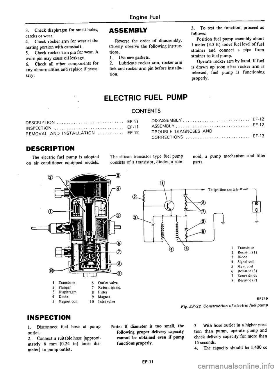
The
electric
fuel
pump
is
adopted
on
air
conditioner
equipped
models
Engine
Fuel
ASSEMBLY
Reverse
the
order
of
disassembly
Closely
observe
the
following
instruc
tions
L
Use
new
gaskets
2
Lubricate
rocker
ann
rocker
arm
link
and
rocker
arm
pin
before
installa
tion
3
To
test
the
function
proceed
as
follows
Position
fuel
pump
assembly
about
I
meter
3
3
ft
above
fuel
level
of
fuel
strainer
and
connect
a
pipe
from
strainer
to
fuel
pump
Operate
rocker
arm
by
hand
If
fuel
is
drawn
up
soon
after
rocker
arm
is
released
fuel
pump
is
functioning
properly
ELECTRIC
FUEL
PUMP
CONTENTS
EF
11
EF
11
EF
12
DISASSEMBL
Y
ASSEMBL
Y
TROUBLE
DIAGNOSES
AND
CORRECTIONS
EF
12
EF
12
The
silicon
transistor
type
fuel
pump
consists
of
a
transistor
diodes
a
sole
I
Tr
lOsistor
6
Ou
tIet
valve
2
Plunger
7
Return
spring
3
Diaphragm
8
Filter
4
Diode
9
Magnet
5
Magnet
coil
10
Inlet
valve
INSPECTION
I
Disconnect
fuel
hose
at
pump
outlet
2
Connect
a
suitable
hose
approxi
mately
6
mm
0
24
in
inner
dia
meter
to
pump
outlet
ev
J
J
Note
If
diameter
is
too
small
the
following
proper
delivery
capacity
cannot
be
obtained
even
if
pump
functions
properly
EF
11
EF
13
noid
a
pump
mechanism
and
filter
parts
I
T
nsistor
2
Re
ist
f
I
3
Dinde
4
Signal
coil
5
Main
coil
6
Resistor
3
7
Zener
dlOdl
8
Resistor
2
EF719
Fig
EF
22
Construction
of
electric
fuel
pump
3
With
hose
outlet
in
a
higher
posi
tion
than
pump
operate
pump
and
check
delivery
capacity
for
more
than
15
seconds
4
The
capacity
should
be
I
400
cc
Page 480 of 537

Body
Electrical
System
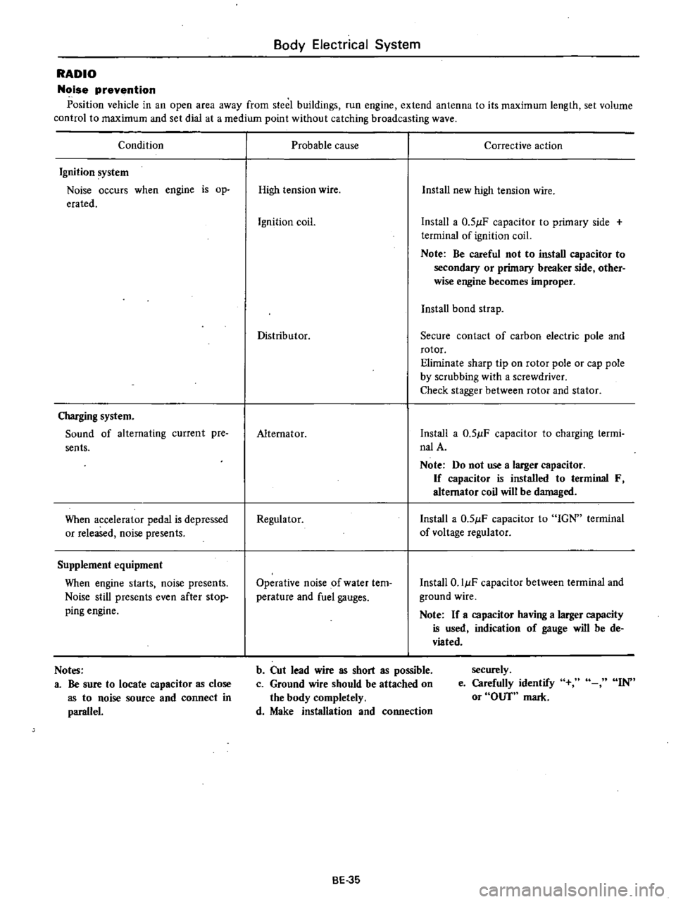
RADIO
Noise
prevention
Position
vehicle
in
an
open
area
away
from
steel
buildings
run
engine
extend
antenna
to
its
maximum
length
set
volume
control
to
maximum
and
set
dial
at
a
medium
point
without
catching
broadcasting
wave
Condition
Ignition
system
Noise
occurs
when
engine
is
op
erated
Charging
system
Sound
of
alternating
current
pre
sents
When
accelerator
pedal
is
depressed
or
released
noise
presents
Supplement
equipment
When
engine
starts
noise
presents
Noise
still
presents
even
after
stop
ping
engine
Notes
a
Be
sure
to
locate
capacitor
as
close
as
to
noise
source
and
connect
in
parallel
Probable
cause
Corrective
action
High
tension
wire
Install
new
high
tension
wire
Ignition
coil
Install
a
0
51lF
capacitor
to
primary
side
terminal
of
ignition
coil
Note
Be
careful
not
to
install
capacitor
to
secondary
or
primary
breaker
side
other
wise
engine
becomes
improper
Install
bond
strap
Distributor
Secure
contact
of
carbon
electric
pole
and
rotor
Eliminate
sharp
tip
on
rotor
pole
or
cap
pole
by
scrubbing
with
a
screwdriver
Check
stagger
between
rotor
and
stator
Alternator
Install
a
0
51lF
capacitor
to
charging
termi
nalA
Note
Do
not
use
a
larger
capacitor
If
capacitor
is
installed
to
terminal
F
alternator
coil
will
be
damaged
Regulator
Install
a
0
51lF
capacitor
to
IGN
terminal
of
voltage
regulator
Operative
noise
of
water
tem
perature
and
fuel
gauges
Install
O
IIlF
capacitor
between
terminal
and
ground
wire
Note
If
a
capacitor
having
a
larger
capacity
is
used
indication
of
gauge
will
be
de
viated
b
Cut
lead
wire
as
short
as
possible
c
Ground
wire
should
be
attached
on
the
body
completely
d
Make
installation
and
connection
securely
e
Carefully
identify
or
OUT
mark
IN
BE
35