fuel type DATSUN PICK-UP 1977 Service Manual
[x] Cancel search | Manufacturer: DATSUN, Model Year: 1977, Model line: PICK-UP, Model: DATSUN PICK-UP 1977Pages: 537, PDF Size: 35.48 MB
Page 25 of 537
CHECKING
CHOKE
MECHANISM
Choke
plate
and
linkage
1
Check
choke
valve
and
mech
anism
for
free
operation
and
clean
or
replace
if
necessary
A
binding
can
result
from
petroleum
gum
formation
on
choke
shaft
or
from
damage
2
Check
bimetal
cover
setting
Index
mark
on
bimetal
cover
is
usually
set
at
center
of
scale
Note
Always
align
the
index
mark
on
bimetal
cover
with
the
center
index
mark
on
choke
housing
3
Every
day
before
starting
engine
depress
the
accelerator
P
dal
to
see
if
choke
valve
is
closed
automatically
If
it
fails
to
be
closed
the
chances
are
that
link
movement
is
unsmooth
Engine
Tune
up
or
that
bimetal
is
out
of
order
Refer
to
Carburetor
in
Section
EF
CHECKING
FUEL
LINES
Hoses
pipings
connections
etc
Check
fuel
lines
for
loose
con
nections
cracks
and
deterioration
Retighten
loose
connections
and
re
place
any
damaged
or
deformed
parts
REPLACING
FUEL
FILTER
Check
for
a
contaminated
filter
and
water
deposit
All
engines
use
a
replaceable
cartridge
type
fuel
filter
as
an
as
sembly
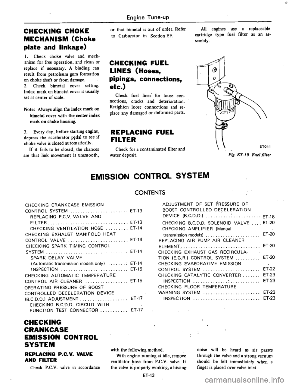
@
Fig
ET
19
Fuel
filler
ET011
EMISSION
CONTROL
SYSTEM
CHECKING
CRANKCASE
EMISSION
CONTROL
SYSTEM
REPLACING
P
C
V
VALVE
AND
FILTER
CHECKING
VENTILATION
HOSE
CHECKING
EXHAUST
MANIFOLD
HEAT
CONTROL
VALVE
CHECKING
SPARK
TIMING
CONTROL
SYSTEM
SPARK
DELAY
VALVE
Automatic
transmission
models
only
INSPECTION
CHECKING
AUTOMATIC
TEMPERATURE
CONTROL
AIR
CLEANER
OPERATING
PRESSURE
OF
BOOST
CONTROLLED
DECELERATION
DEVICE
B
CD
D
I
ADJUSTMENT
CHECKING
B
C
DD
CIRCUIT
WITH
FUNCTION
TEST
CONNECTOR
CHECKING
CRANKCASE
EMISSION
CONTROL
SYSTEM
REPLACING
P
C
V
VALVE
AND
FILTER
Check
P
C
V
valve
in
accordance
CONTENTS
ET
13
ET
13
ET
14
ET
14
ET
14
ET
14
ET
15
ET
15
ET
17
ET
17
ADJUSTMENT
OF
SET
PRESSURE
OF
BOOST
CONTROLLED
DECELERATION
DEVICE
B
CD
D
CHECKING
B
C
D
D
SOLENOID
VALVE
CHECKING
AMPLIFIER
Manual
transmission
models
REPLACING
AIR
PUMP
AIR
CLEANER
ELEMENT
CHECKING
EXHAUST
GAS
RECIRCULA
TION
E
G
R
CONTROL
SYSTEM
CHECKING
EVAPORATIVE
EMISSION
CONTROL
SYSTEM
CHECKING
CATALYTIC
CONVERTER
INSPECTION
CHECKING
FLOOR
TEMPERATURE
WARNING
SYSTEM
INSPECTION
with
the
following
method
With
engine
running
at
idle
remove
ventilator
ose
from
P
C
V
valve
If
the
valve
is
properly
working
a
hissing
ET
13
ET
18
ET
20
ET
20
ET
20
ET
20
ET
22
ET
23
ET
23
ET
23
ET
23
noise
will
be
heard
as
air
passes
through
the
valve
and
a
strong
vacuum
should
be
felt
immediately
when
a
finger
is
placed
over
valve
inlet
Page 27 of 537
Engine
Tune
up
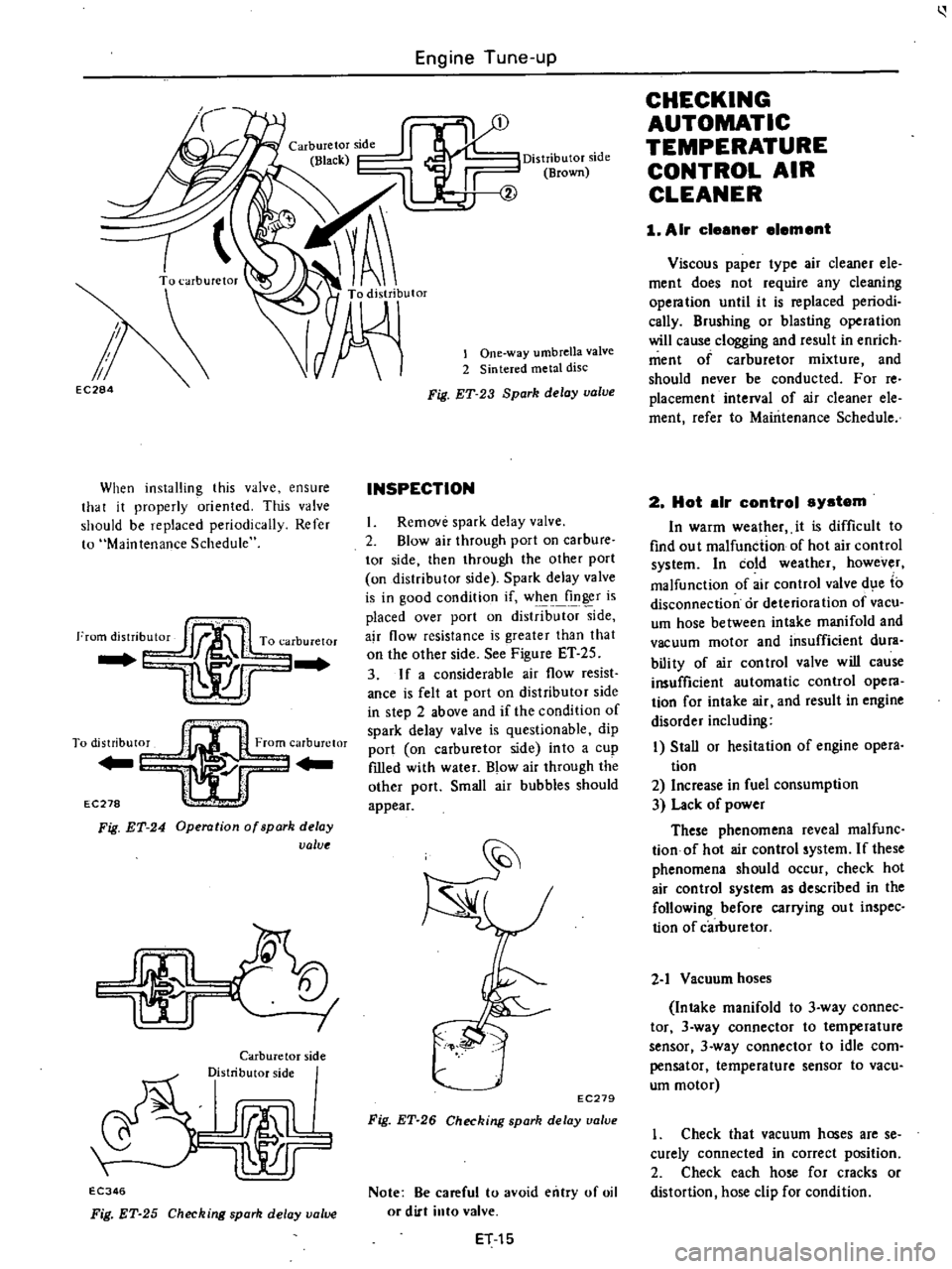
EC284
When
installing
this
valve
ensure
that
it
properly
oriented
This
valve
should
be
replaced
periodically
Refer
to
Maintenance
Schedule
I
To
distribut0
From
carburetor
Yl
r
EC278
l
Fig
ET
24
Operation
of
spark
delay
value
I
I
Carburetor
side
Distributor
side
rJmlL
lr
EC346
Fig
ET
25
Checking
spark
delay
value
Distributor
side
Brown
lOne
way
umbrella
valve
2
Sintered
metal
disc
Fig
ET
23
Spark
delay
valve
INSPECTION
I
Remove
spark
delay
valve
2
Blow
air
through
port
on
carbure
tor
side
then
through
the
other
port
on
distributor
side
Spark
delay
valve
is
in
good
condition
if
when
finger
is
placed
over
port
on
distrib
side
ajr
flow
resistance
is
greater
than
that
on
the
other
side
See
Figure
ET
25
3
If
a
considerable
air
flow
resist
ance
is
felt
at
port
on
distributor
side
in
step
2
above
and
if
the
condition
of
spark
delay
valve
is
questionable
dip
port
on
carburetor
side
into
a
cup
fIlled
with
water
Blow
air
through
the
other
port
Small
air
bubbles
should
appear
EC279
Fig
ET
26
Checking
spark
delay
ualue
Note
Be
careful
to
avoid
entry
of
oil
or
dirt
into
valve
ET
15
CHECKING
AUTOMATIC
TEMPERATURE
CONTROL
AIR
CLEANER
1
Air
cleener
element
Viscous
paper
type
air
cleaner
ele
ment
does
not
require
any
cleaning
opera
tion
until
it
is
replaced
periodi
cally
Brushing
or
blasting
operation
will
cause
clogging
and
result
in
enrich
ment
of
carburetor
mixture
and
should
never
be
conducted
For
reo
placement
interval
of
air
cleaner
ele
ment
refer
to
Maintenance
Schedule
2
Hot
elr
control
system
In
warm
wealher
it
is
difficult
to
find
ou
t
malfunction
of
hot
air
control
system
In
cold
weather
however
malfunction
of
air
control
valve
d
e
to
disconnection
or
deterioration
of
vacu
um
hose
between
intake
manifold
and
vacuum
motor
and
insufficient
dura
bili
ty
of
air
con
trol
valve
will
cause
insufficient
automatic
control
opera
tion
for
intake
air
and
result
in
engine
disorder
including
I
Stall
or
hesitation
of
engine
opera
tion
2
Increase
in
fuel
consumption
3
Lack
of
power
These
phenomena
reveal
malfunc
tionof
hot
air
control
system
If
these
phenomena
should
occur
check
hot
air
control
system
as
described
in
the
following
before
carrying
ou
t
inspec
tion
of
carburetor
2
1
Vacuum
hoses
Intake
manifold
to
3
way
connec
tor
3
way
connector
to
temperature
sensor
3
way
connector
to
idle
com
pensator
temperature
sensor
to
vacu
um
motor
1
Check
that
vacuum
hoses
are
se
curely
connected
in
correct
position
2
Check
each
hose
for
cracks
or
distortion
hose
clip
for
condition
Page 66 of 537
PRECAUTIONS
CYLINDER
HEAD
PRECAUTIONS
I
Use
thoroughly
cleaned
parts
Especially
make
sure
that
oil
holes
are
clear
of
foreign
matter
2
When
installing
sliding
parts
such
as
bearings
be
s
uIe
to
apply
engine
oil
to
them
3
Use
new
packing
and
oil
seals
4
Do
not
reuse
lock
washers
5
Keep
tools
and
work
benches
clean
6
Keep
necessary
parts
and
tools
near
at
hand
7
Be
sure
to
follow
specified
tight
ening
torque
and
order
8
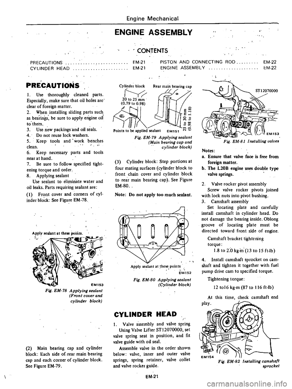
Applying
sealant
Use
sealant
to
eliminate
water
and
oil
leaks
Parts
requiring
sealant
are
I
Front
cover
and
corners
of
cyl
inder
block
See
Figure
EM
78
EM153
Fig
EM
78
Applying
alant
Front
cover
and
cylinder
block
2
Main
bearing
cap
and
cylinder
block
Each
side
of
rear
main
bearing
cap
and
each
corner
of
cylinder
block
See
Figure
EM
79
Engine
Mechanical
ENGINE
ASSEMBLY
CONTENTS
EM
21
EM
21
PISTON
AND
CONNECTING
ROD
ENGINE
ASSEMBLY
EM
22
EM
22
Cylinder
block
Rear
main
bearing
cap
20to2Smm
Ill
Points
to
be
applied
sealant
EM151
s
e
00
000
o
Fig
EM
79
Applying
sealanl
Main
bearing
cap
and
cylinder
block
3
Cylinder
block
Step
portions
at
four
mating
surfaces
cylinder
block
to
front
chain
cover
and
cylinder
block
to
rear
main
bearing
cap
See
Figure
EM
80
Note
Do
not
apply
too
much
sealant
J
Apply
sealant
at
hese
points
EM152
Fig
EM
80
Applying
sealant
Cylinder
block
CYLINDER
HEAD
Valve
assembly
and
valve
spring
Using
Valve
Lifter
STl2070000
set
valve
pring
seat
in
position
and
fit
valve
guide
with
oil
seaL
Assemble
valve
in
the
order
shown
below
valve
inner
and
outer
valve
springs
spring
retainer
valve
collet
and
valve
rocker
guide
EM
21
Fig
EM
81
Installing
valves
Notes
a
Ensure
that
valve
face
is
free
from
foreign
matter
b
The
L20B
engine
uses
double
type
valve
springs
2
Valve
rocker
pivot
assembly
Screw
valve
rocker
pivots
joined
with
lock
nuts
into
pivot
hushing
3
Camshaft
assembly
Set
locating
plate
and
carefully
install
camshaft
in
cylinder
head
Do
not
damage
the
bearing
inside
Oblong
groove
of
locating
plate
must
be
directed
toward
front
side
of
engine
Camshaft
bracket
tightening
torque
1
8
to
2
0
kg
in
13
to
15
ft
lb
4
Install
camshaft
sprocket
on
earn
shaft
and
tighten
it
together
with
fuel
pump
drive
cam
to
specified
torque
Tightening
torque
12
tol6
kg
m
87
to
116
ft
lb
this
time
check
camshaft
end
Fig
EM
82
Installing
camshaft
sprocket
Page 69 of 537
2
Turn
crankshaft
until
No
I
pis
ton
is
at
T
D
C
on
its
compression
stroke
3
Make
sure
thai
camshaft
sprock
et
location
notch
and
plate
oblong
groove
are
aligned
at
their
correct
positions
4
When
installing
cylinder
head
make
sure
that
all
valves
are
apart
from
heads
of
pistons
5
Do
not
rotate
crankshaft
and
camshaft
separately
or
valves
will
hit
heads
of
pistons
6
Temporarily
tighten
two
bolts
CD
V
sJiown
in
Fig
re
EM
96
Tightening
torque
2
kg
m
14
ft
b
15
Install
crankshaft
sprocket
and
oil
pump
drive
gear
and
fit
oil
thrower
Note
Make
sure
lhat
maling
marks
of
crankshaft
sprocket
face
10
Cront
16
Install
timing
chain
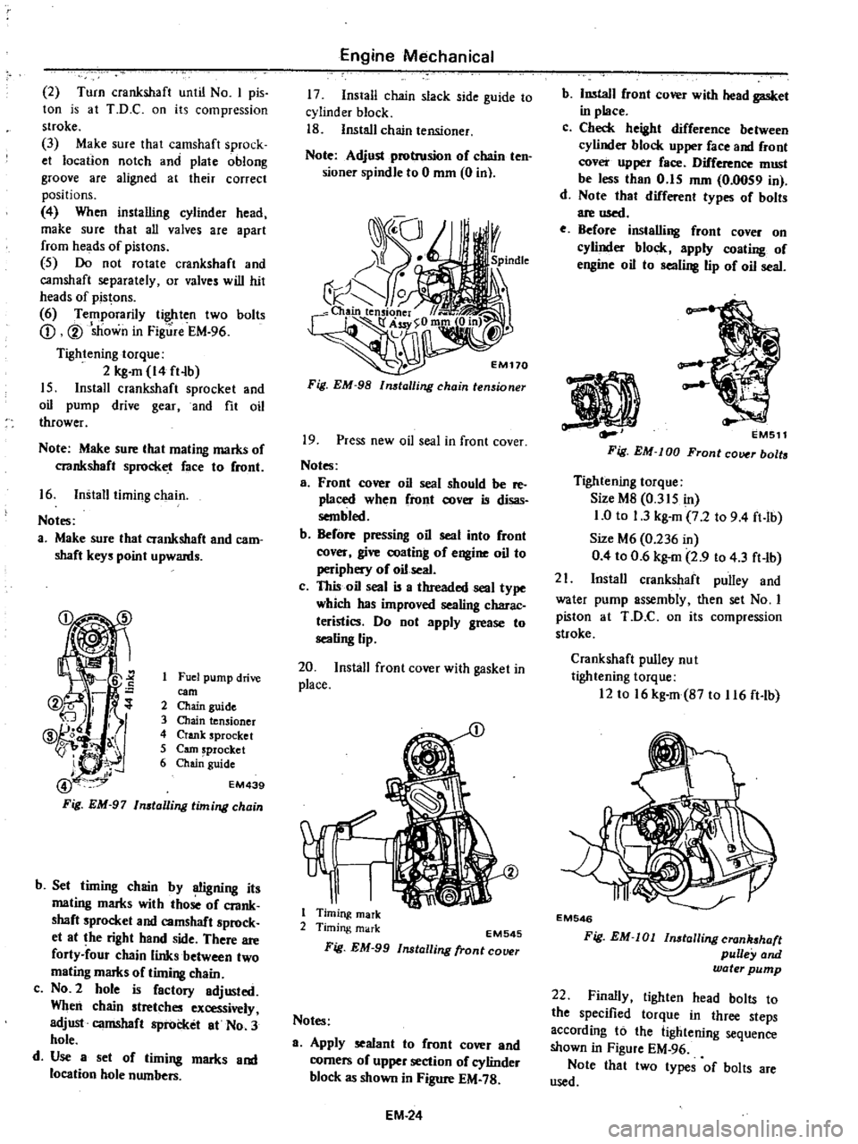
Noles
a
Make
sure
that
crankshaft
and
cam
shaft
keys
point
upwards
Fuel
pump
drive
earn
2
Chain
guide
3
Chain
tensioner
4
Crank
sprocket
5
earn
sprocket
6
Chai
guide
EM439
b
Set
timing
chain
by
OOgning
its
mating
marks
with
those
oC
crank
shaft
sprocket
and
camshaft
sprock
et
at
the
right
hand
side
There
are
forty
four
chain
links
between
two
mating
marks
of
timing
chain
c
NO
2
hole
is
Cactory
adjusted
When
chain
stretches
excessively
adjust
camshaft
sprocket
at
No
3
hole
d
Use
a
set
of
timing
marks
and
location
hole
numbers
Engine
Mechanical
17
Install
chain
slack
side
guide
to
cylinder
block
18
Install
chain
tensioner
Note
Adjust
protrusion
oC
chain
ten
sioner
spindle
to
0
mm
0
in
Fig
EM
98
lmtalling
chain
tensioner
19
Press
new
oil
seal
in
front
cover
Notes
a
Front
cover
oil
seal
should
be
reo
placed
when
Cront
cover
is
disas
sembled
b
BeCore
pressing
oil
seal
into
Cront
cover
give
coating
of
engine
oil
to
periphery
of
oil
seal
c
This
oil
seal
is
a
threaded
seal
type
which
has
improved
sealing
charac
teristics
Do
not
apply
grease
to
sealing
lip
20
Install
front
cover
with
gasket
in
place
1
Timing
mark
2
Timing
mark
EM545
Fig
EM
99
Installing
fronl
COlHlr
Notes
a
Apply
sealant
to
Cront
cover
and
corners
oC
upper
section
of
cylinder
block
as
shown
in
Figure
EM
78
EM
24
b
Install
Cront
cover
with
head
gasket
in
place
c
Check
height
diCCerence
between
cylinder
block
upper
Cace
and
Cront
cover
upper
Cace
DifCerence
must
be
less
than
0
15
mm
0
0059
in
d
Note
that
difCerent
types
oC
bolts
are
used
e
Before
installing
front
cover
on
cylinder
block
apply
coating
oC
engine
oil
10
sealing
lip
of
oil
seal
EMS11
Fig
EM
lOD
Front
cover
bolts
Tightening
torque
Size
M8
0
315
in
1
0
to
1
3
kg
m
7
2
to
9
4
ft
lb
Size
M6
0
236
in
0
4
to
0
6
kg
m
2
9
to
4
3
ft
lb
21
Install
crankshaft
pulley
and
water
pump
assembly
then
set
No
I
piston
at
ToO
C
on
its
compression
stloke
Crankshaft
pulley
nu
I
tightening
torque
12
to
16
kg
m
B7
to
116
ft
lb
EM546
Fig
EM
Ol
lnstallingcran
haft
pulley
and
water
pump
22
Finally
tighten
head
bolts
to
the
specified
torque
in
three
steps
according
to
the
lightening
sequence
shown
in
Figure
EM
96
Note
thai
Iwo
types
of
bolts
are
used
Page 98 of 537
Engine
Fuel
AUTOMATIC
TEMPERATURE
CONTROL
A
T
C
AIR
CLEANER
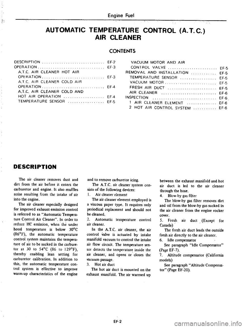
DESCRIPTION
OPERATION
A
T
C
AIR
CLEANER
HOT
AIR
OPERATION
A
T
C
AIR
CLEANER
COLD
AIR
OPERATION
A
T
C
AIR
CLEANER
COLD
AND
HOT
AIR
OPERATION
TEMPERATURE
SENSOR
DESCRIPTION
The
air
cleaner
removes
dust
and
dirt
from
the
air
before
it
enters
the
carburetor
and
engine
It
also
muffles
noise
resulting
from
the
intake
of
air
into
the
engine
The
air
cleaner
especially
designed
for
improved
exhaust
emission
control
is
referred
to
as
Automatic
Tempera
ture
Control
Air
Cleaner
In
order
to
reduce
HC
emission
when
the
under
hood
temperature
is
below
300C
860F
the
automatic
temperature
control
system
maintains
the
tempera
ture
of
air
to
be
sucked
in
the
carbure
tor
at
30
to
540C
86
to
1290F
thereby
enabling
lean
setting
for
carburetor
calibration
n
addition
to
this
the
automatic
temperature
con
twl
system
is
effective
to
improve
warm
up
characteristics
of
the
engine
CONTENTS
EF
2
EF
3
VACUUM
MOTOR
AND
AIR
CONTROL
VALVE
REMOVAL
AND
INSTALLATION
TEMPERATURE
SENSOR
VACUUM
MOTOR
FRESH
AIR
DUCT
AIR
CLEANER
INSPECTION
1
AIR
CLEANER
ELEMENT
2
HOT
AIR
CONTROL
SYSTEM
EF
3
EF
4
EF
4
EF
5
and
to
remove
carburetor
icing
The
A
T
C
air
cleaner
system
con
sists
of
the
following
devices
1
Air
cleaner
element
The
air
cleaner
element
employed
is
a
viscous
paper
type
It
requires
only
periodical
replacment
and
should
not
be
cleaned
2
Automatic
temperature
control
air
cleaner
In
the
A
T
C
air
cleaner
the
air
control
valve
is
actuated
by
intake
manifold
vacuum
to
control
the
intake
air
flow
circuit
The
temperature
sen
sor
detects
the
temperature
inside
the
air
cleaner
and
opens
or
closes
the
vacuum
passage
3
Hot
air
duct
The
hot
air
duct
is
mounted
on
the
exhaust
manifold
The
air
warmed
up
EF
2
EF
5
EF
5
EF
5
EF
5
EF
5
EF
6
EF
6
EF
6
EF
6
between
the
exhaust
manifold
and
hot
air
duct
is
led
to
the
air
cleaner
through
the
hose
4
Blow
by
gas
filter
The
blow
by
gas
nIter
removes
dirt
and
oil
from
the
blow
by
gas
sucked
in
the
air
cleaner
from
the
engine
rocker
cover
5
Fresh
air
duct
Except
for
Canada
The
fresh
air
duct
leads
the
outside
fresh
air
directly
to
the
air
cleaner
6
Idle
compensator
See
paragraph
Idle
Compensator
Page
EF
7
7
Altitude
compensator
California
models
See
paragraph
Altitude
Compensa
tor
Page
EF
20
Page 102 of 537
r
AIR
CLEANER
1
Loosen
bolts
securing
air
cleaner
to
air
cleaner
bracket
2
Loosen
air
cleaner
lock
bolt
and
remove
air
cleaner
from
carburetor
Disconnect
the
following
hoses
when
dismounting
air
cleaner
Under
hood
air
inlet
hose
Hot
air
inlet
hose
Vacuum
hose
Sensor
to
intake
manifold
Vacuum
hose
Sensor
to
vacuum
motor
Vacuum
hose
Idle
compensator
to
intake
manifold
Hose
Air
pump
to
air
cleaner
Hose
AB
valve
to
air
cleaner
Hose
Carburetor
to
air
cleaner
Blow
by
hose
Air
cleaner
to
rocker
cover
Hose
Air
control
vaive
to
air
cleaner
California
models
only
3
To
install
reverse
the
removal
procedure
INSPECTION
1
AIR
CLEANER
ELEMENT
Viscous
paper
type
air
cleaner
ele
ment
does
not
require
any
cleaning
operation
until
it
is
replaced
periodi
cally
Brushing
or
blasting
operation
will
cause
clogging
and
result
in
enrich
ment
of
carburetor
mixture
and
should
never
be
conducted
For
reo
placement
interval
of
air
cleaner
ele
ment
refer
to
Maintenance
Sched
ule
2
HOT
AIR
CONTROL
SYSTEM
In
warm
weather
it
is
difficult
to
find
out
malfunction
of
hot
air
control
system
In
cold
wea
thee
however
malfunction
of
air
control
valve
due
to
disconnection
or
deterioration
of
vacu
um
hose
between
intake
manifold
and
vacuum
motor
and
insufficient
dura
bility
of
air
control
valve
will
cause
insufficient
automatic
control
opera
tion
for
intake
air
and
result
in
engine
disorder
including
I
Stall
or
hesitation
of
engine
oper
ation
2
Increase
in
fuel
consumption
3
uck
of
power
Engine
Fuel
These
phenomena
reveal
malfunc
tion
of
hot
air
control
system
If
these
phenomena
should
occur
check
hot
air
control
system
as
described
in
the
following
before
carrying
out
inspec
tion
of
carburetor
2
1
Vacuum
hose
Intake
manifold
to
3
way
connec
tor
3
way
connector
to
temperature
sensor
3
way
connector
to
idle
com
pensator
temperature
sensor
to
vacu
um
motor
I
Check
that
vacuum
hoses
are
se
curely
connected
in
correct
postion
2
Check
each
hose
for
cracks
or
distortion
hose
clip
for
condition
Note
Vacuum
hose
position
R
H
side
of
Nissan
mark
on
the
top
of
sensor
is
for
intake
manifold
L
U
side
of
the
mark
is
for
vacuum
motor
2
2
Vacuum
motor
I
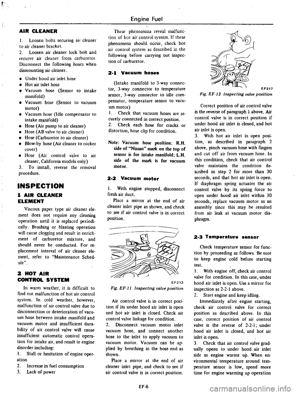
With
engine
stopped
disconnect
fresh
air
duct
Place
a
mirror
at
the
end
of
air
cleaner
inlet
pipe
as
shown
and
check
to
see
if
air
con
trol
valve
is
in
correct
position
EF213
Fig
EF
11
Inspecting
valve
position
Air
control
valve
is
in
correct
posi
tion
if
its
under
hood
air
inlet
is
open
and
hot
air
inlet
is
closed
Check
air
control
valve
linkage
for
condition
2
Disconnect
vacuum
motor
inlet
vacuum
hose
and
connect
another
hose
to
the
inlet
to
apply
vacuum
to
vacuum
motor
Vacuum
can
be
ap
plied
by
breathing
in
the
hose
end
as
shown
Place
a
mirror
at
the
end
of
air
cleaner
inlet
pipe
and
check
to
see
if
air
control
valve
is
in
correct
position
EF
6
EF217
Fig
EF
12
Inspecting
valve
position
Correct
position
of
air
control
valve
is
the
reverse
of
paragraph
J
above
Air
control
valve
is
in
correct
position
if
under
hood
air
inlet
is
closed
and
hot
air
inlet
is
open
3
With
hot
air
inlet
in
open
posi
tion
as
described
in
paragraph
2
above
pinch
vacuum
hose
with
fingers
and
cut
off
air
from
vacuum
hose
In
this
condition
check
that
air
control
valve
maintains
the
condition
de
scribed
in
step
2
for
more
than
30
seconds
and
that
hot
air
inlet
is
open
If
diaphragm
spring
actuates
the
air
control
valve
by
its
spring
force
to
open
under
hood
air
inlet
within
30
seconds
replace
vacuum
motor
as
an
assembly
since
this
may
be
resulted
from
air
leak
at
vacuum
motor
dia
phragm
2
3
Temperature
ensor
Check
temperature
sensor
for
func
tion
by
proceeding
as
follows
Be
sure
to
keep
engine
cold
before
starting
test
I
With
engine
off
check
air
control
valve
for
condition
In
this
case
under
hood
air
inlet
is
open
Use
a
mirror
for
inspection
as
2
2
1
above
2
Start
engine
and
keep
idling
Immediately
after
engine
starting
check
air
control
valve
for
correct
position
as
described
above
In
this
case
correct
position
of
air
control
valve
is
the
reverse
of
2
2
I
under
hood
air
inlet
is
closed
and
hot
air
inlet
is
open
3
Check
that
air
control
valve
grad
ually
opens
to
under
hood
air
inlet
side
as
engine
warms
up
When
en
vironmental
temperature
around
tern
perature
sensor
is
low
spend
more
time
for
engine
warming
up
operation
Page 104 of 537
Engine
Fuel
REMOVAL
AND
INSTALLATION
Remove
air
cleaner
cover
2
Remove
hose
connecting
idle
compensator
and
3
way
connector
3
Loosen
screws
securing
idle
com
pensator
to
air
cleaner
then
remove
idle
compensator
Notes
a
When
removing
idle
compensator
remove
gasket
and
plate
b
When
removing
screw
securing
idle
compensator
to
air
cleaner
be
care
ful
not
to
miss
the
saew
4
To
install
reverse
the
removal
procedure
INSPECTION
I
Check
tha
t
valve
IS
m
closed
position
when
bi
metal
temperature
is
lower
than
operating
temperature
To
check
breathe
air
into
tube
or
suck
DESCRIPTION
The
fuel
fJlter
is
a
cartridge
type
It
uses
a
paper
element
which
can
be
checked
for
condition
from
the
out
side
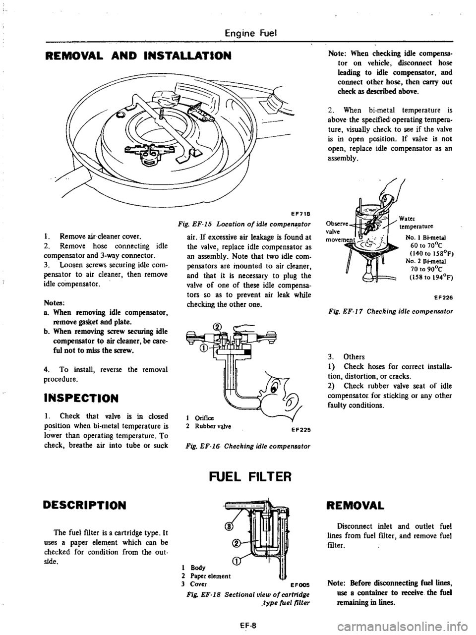
EF718
Fig
EF
15
Location
of
idle
compenl
otor
air
If
excessive
air
leakage
is
found
at
the
valve
replace
idle
compensator
as
an
assembly
Note
that
two
idle
com
pensators
are
mounted
to
air
cleaner
and
that
it
is
necessary
to
plug
the
valve
of
one
of
these
idle
compensa
tors
so
as
to
prevent
air
leak
while
checking
the
other
one
@
CD
I
tl
1
Orifice
2
Rubber
valve
EF225
Fig
EF
16
Checking
idle
compelll
lor
FUEL
FILTER
1
Body
2
Paper
element
3
Cover
1
EFOO5
Fig
EF
18
Sectional
view
of
cartridge
type
fuel
filter
EF
8
Note
When
checking
idle
compensa
tor
on
vehicle
disconnect
hose
leading
to
idle
compensator
and
connect
other
hose
then
carry
out
check
as
descn
bed
above
2
When
bi
metal
temperature
is
above
the
specified
operating
tempera
ture
visually
check
to
see
if
the
valve
is
in
open
position
If
valve
is
not
open
replace
idle
compensator
as
an
assembly
Watcr
temperature
Observe
valve
11t
No
1
Bknctal
60
to
70De
140
to
1580F
NO
2
Bi
metal
70
to
900C
158to
1940F
EF226
Fig
EF
17
Checking
idle
compensator
3
Others
I
Check
hoses
for
correct
installa
tion
distortion
or
cracks
2
Check
rubber
valve
seat
of
idle
compensator
for
sticking
or
any
other
faulty
conditions
REMOVAL
Disconnect
inlet
and
outlet
fuel
lines
from
fuel
fJlter
and
remove
fuel
fJlter
Note
Before
disconnecting
fuel
lines
use
a
container
to
receive
the
fuel
remaining
in
lines
Page 105 of 537
DESCRIPTION
FUEL
PUMP
TESTING
STATIC
PRESSURE
TEST
CAPACITY
TEST
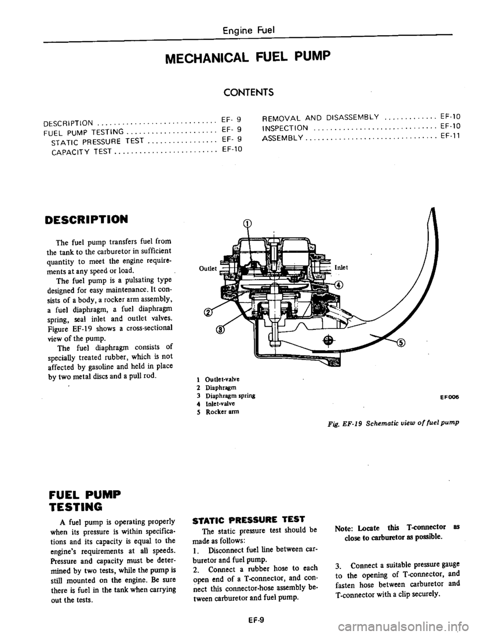
DESCRIPTION
The
fuel
pump
transfers
fuel
from
the
tank
to
the
carburetor
in
sufficient
quantity
to
meet
the
engine
require
ments
at
any
speed
or
load
The
fuel
pump
is
a
pulsating
type
designed
for
easy
maintenance
It
con
sists
of
a
body
a
rocker
arm
assembly
a
fuel
diaphragm
a
fuel
diaphragm
spring
seal
inlet
and
outlet
valves
Figure
EF
19
shows
a
cross
sectional
view
of
the
pump
The
fuel
diaphragm
consists
of
specially
treated
rubber
which
is
not
affected
by
gasoline
and
held
in
place
by
two
metal
discs
and
a
pull
rod
FUEL
PUMP
TESTING
A
fuel
pump
is
operating
properly
when
its
pressure
is
within
specifica
tions
and
its
capacity
is
equal
to
the
engine
s
requirements
at
all
speeds
Pressure
and
capacity
must
be
deter
mined
by
two
tests
while
the
pump
is
still
mounted
on
the
engine
Be
sure
there
is
fuel
in
the
tank
when
carrying
out
the
tests
Engine
Fuel
MECHANICAL
FUEL
PUMP
CONTENTS
EF
9
EF
9
EF
9
EF
10
REMOVAL
AND
DISASSEMBLY
INSPECTION
ASSEMBL
Y
EF
10
EF
10
EF
11
1
1
Outlet
valve
2
Diaphragm
3
Diaphragm
spring
4
Inlet
valve
S
Rocker
ann
EF006
Fig
EF
19
Schematic
view
of
fuel
pump
STATIC
PRESSURE
TEST
The
static
pressure
test
should
be
made
as
follows
I
Disconnect
fuel
line
between
car
buretor
and
fuel
pump
2
Connect
a
rubber
hose
to
each
open
end
of
a
T
connector
and
con
nect
this
connector
hose
assembly
be
tween
carburetor
and
fuel
pump
Note
Locate
this
T
connector
as
close
to
carburetor
as
possible
3
Connect
a
suitable
pressure
gauge
to
the
opening
of
T
connector
and
fasten
hose
between
carburetor
and
T
connector
with
a
clip
securely
EF
9
Page 107 of 537
3
Check
diaphragm
for
small
holes
carcks
or
wear
4
Check
rocker
arm
for
wear
at
the
mating
portion
with
camshaft
5
Check
rocker
arm
pin
for
wear
A
worn
pin
may
cause
oil
leakage
6
Check
all
other
components
for
any
abnormalities
and
replace
if
neces
sary
DESCRIPTION
INSPECTION
REMOVAL
AND
INSTALLATION
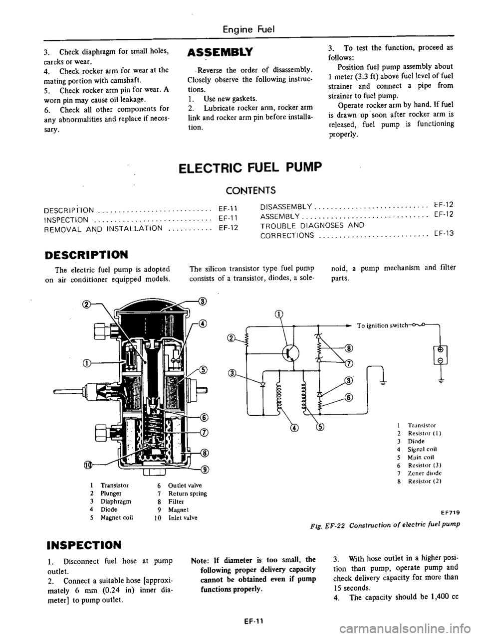
DESCRIPTION
The
electric
fuel
pump
is
adopted
on
air
conditioner
equipped
models
Engine
Fuel
ASSEMBLY
Reverse
the
order
of
disassembly
Closely
observe
the
following
instruc
tions
L
Use
new
gaskets
2
Lubricate
rocker
ann
rocker
arm
link
and
rocker
arm
pin
before
installa
tion
3
To
test
the
function
proceed
as
follows
Position
fuel
pump
assembly
about
I
meter
3
3
ft
above
fuel
level
of
fuel
strainer
and
connect
a
pipe
from
strainer
to
fuel
pump
Operate
rocker
arm
by
hand
If
fuel
is
drawn
up
soon
after
rocker
arm
is
released
fuel
pump
is
functioning
properly
ELECTRIC
FUEL
PUMP
CONTENTS
EF
11
EF
11
EF
12
DISASSEMBL
Y
ASSEMBL
Y
TROUBLE
DIAGNOSES
AND
CORRECTIONS
EF
12
EF
12
The
silicon
transistor
type
fuel
pump
consists
of
a
transistor
diodes
a
sole
I
Tr
lOsistor
6
Ou
tIet
valve
2
Plunger
7
Return
spring
3
Diaphragm
8
Filter
4
Diode
9
Magnet
5
Magnet
coil
10
Inlet
valve
INSPECTION
I
Disconnect
fuel
hose
at
pump
outlet
2
Connect
a
suitable
hose
approxi
mately
6
mm
0
24
in
inner
dia
meter
to
pump
outlet
ev
J
J
Note
If
diameter
is
too
small
the
following
proper
delivery
capacity
cannot
be
obtained
even
if
pump
functions
properly
EF
11
EF
13
noid
a
pump
mechanism
and
filter
parts
I
T
nsistor
2
Re
ist
f
I
3
Dinde
4
Signal
coil
5
Main
coil
6
Resistor
3
7
Zener
dlOdl
8
Resistor
2
EF719
Fig
EF
22
Construction
of
electric
fuel
pump
3
With
hose
outlet
in
a
higher
posi
tion
than
pump
operate
pump
and
check
delivery
capacity
for
more
than
15
seconds
4
The
capacity
should
be
I
400
cc
Page 110 of 537
Engine
Fuel
CARBURETOR
CONTENTS
DESCRIPTION
EF
14
CHOKE
UNLOADER
EF
23
STRUCTURE
AND
OPERATION
EF
14
ELECTRIC
AUTOMATIC
CHOKE
EF
24
PRIMARY
SYSTEM
EF
15
INTERLOCK
OPENING
OF
PRIMARY
AND
SECONDARY
SYSTEM
EF
16
SECONDARY
THROTTLE
VALVE
EF
24
ANTI
DIESELING
SYSTEM
EF
17
DASH
POT
EF
25
FLOAT
SYSTEM
EF
18
ACCELERATING
PUMP
EF
25
BOOST
CONTROLLED
DECELERATION
ANTI
DIESELING
SOLENOID
VALVE
EF
25
DEVICE
B
C
D
D
EF
1B
B
C
D
D
CIRCUIT
WITH
FUNCTION
ELECTRIC
AUTOMATIC
CHOKE
EF
20
TEST
CONNECTOR
EF
25
DASH
POT
SYSTEM
EF
20
ALTITUDE
COMPENSATOR
ALTITUDE
COMPENSATOR
California
modelsl
EF
29
California
models
EF
20
MAJOR
SERVICE
OPERATION
EF
29
ADJUSTMENT
AND
INSPECTION
EF
21
REMOVAL
EF
29
CARBURETOR
IDLE
RPM
AND
DISASSEMBLY
AND
ASSEMBLY
EF
30
MIXTURE
RATIO
EF
21
CLEANING
AND
INSPECTION
EF
34
FUEL
LEVEL
EF
22
SERVICE
DATA
AND
SPECIFICATIONS
EF
35
FAST
IDLE
EF
22
TROU8LE
DIAGNOSES
AND
VACUUM
BREAK
EF
23
CORRECTIONS
EF
36
DESCRIPTION
The
carburetors
are
of
down
draft
two
barrel
types
which
produce
the
optimum
air
fuel
mixture
under
all
operating
conditions
They
present
several
distinct
features
of
importance
to
the
vehicle
owners
A
summary
of
the
features
is
as
follows
1
A
slow
economizer
to
make
a
smooth
connection
with
acceleration
or
deceleration
during
light
load
run
ning
It
also
assures
stable
low
speed
performance
2
An
idle
limiter
to
reduce
harmful
exhaust
emissions
to
a
minimum
3
A
B
C
D
D
device
for
reducing
hydrocarbon
H
C
emissions
4
An
electric
automatic
choke
to
facilitate
cold
starting
and
to
reduce
exhaust
emissions
5
An
anti
dieseling
solenoid
to
eliminate
dieseling
run
on
6
A
power
valve
or
vacuum
actu
ated
booster
to
ensure
smooth
high
speed
operation
7
The
carburetor
comes
equipped
with
dash
pot
which
ensures
smooth
deceleration
without
engine
stall
under
all
operating
conditions
8
The
hand
operated
altitude
com
pensator
is
installed
in
the
California
models
EF
14
STRUCTURE
AND
OPERATION
These
carburetors
consist
of
a
primary
system
for
normal
running
and
a
secondary
system
for
full
load
running
A
float
system
common
to
both
primary
and
secondary
systems
a
se
condary
switch
over
mechanism
an
accelerating
mechanism
etc
are
also
attached
An
anti
dieseling
solenoid
valve
and
a
power
valve
mechanism
are
also
installed
The
hand
operated
altitude
com
pensator
corrects
air
fuel
mixture
to
an
optimum
ratio