fuel tank removal DATSUN PICK-UP 1977 Service Manual
[x] Cancel search | Manufacturer: DATSUN, Model Year: 1977, Model line: PICK-UP, Model: DATSUN PICK-UP 1977Pages: 537, PDF Size: 35.48 MB
Page 105 of 537
DESCRIPTION
FUEL
PUMP
TESTING
STATIC
PRESSURE
TEST
CAPACITY
TEST
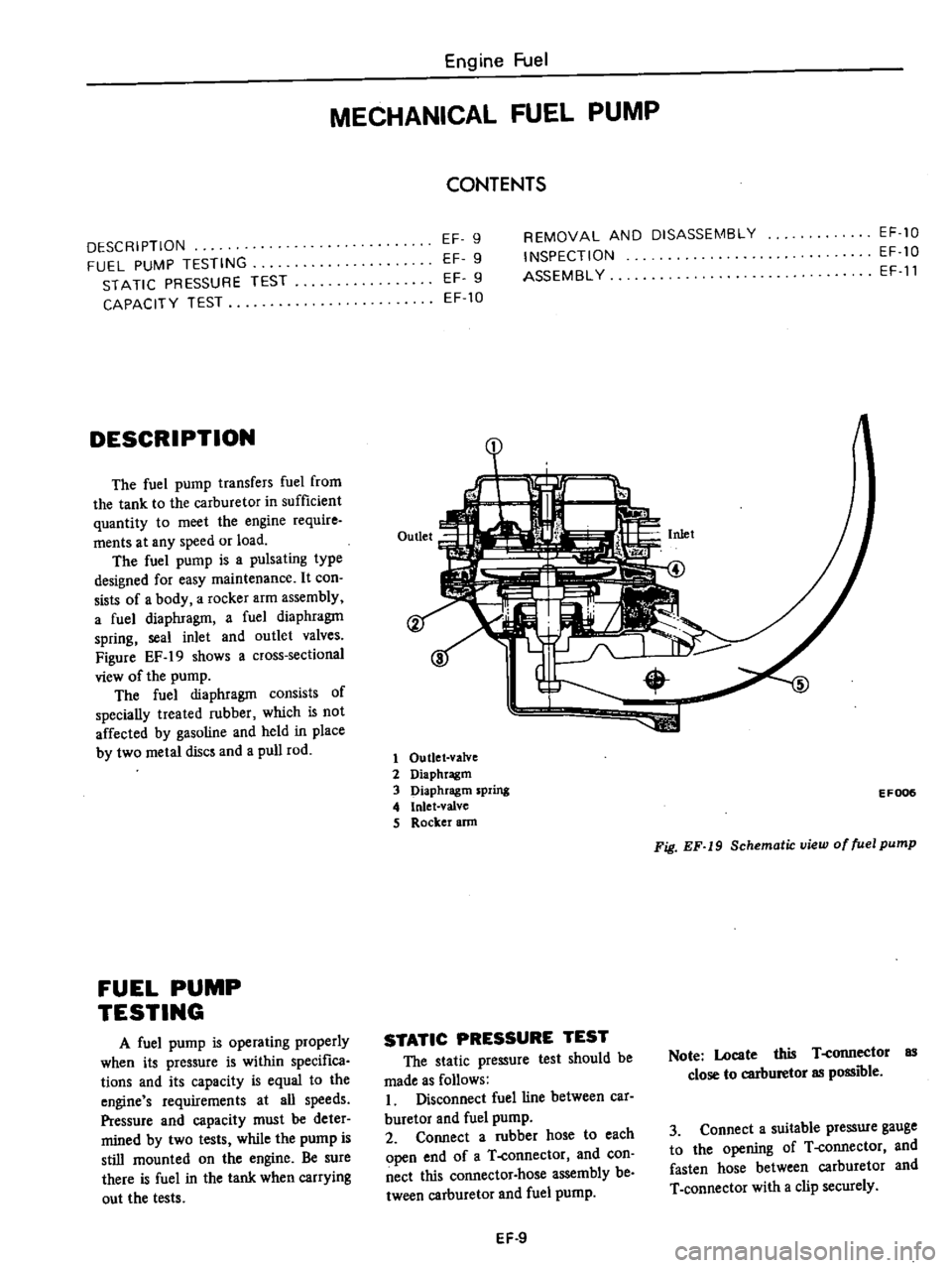
DESCRIPTION
The
fuel
pump
transfers
fuel
from
the
tank
to
the
carburetor
in
sufficient
quantity
to
meet
the
engine
require
ments
at
any
speed
or
load
The
fuel
pump
is
a
pulsating
type
designed
for
easy
maintenance
It
con
sists
of
a
body
a
rocker
arm
assembly
a
fuel
diaphragm
a
fuel
diaphragm
spring
seal
inlet
and
outlet
valves
Figure
EF
19
shows
a
cross
sectional
view
of
the
pump
The
fuel
diaphragm
consists
of
specially
treated
rubber
which
is
not
affected
by
gasoline
and
held
in
place
by
two
metal
discs
and
a
pull
rod
FUEL
PUMP
TESTING
A
fuel
pump
is
operating
properly
when
its
pressure
is
within
specifica
tions
and
its
capacity
is
equal
to
the
engine
s
requirements
at
all
speeds
Pressure
and
capacity
must
be
deter
mined
by
two
tests
while
the
pump
is
still
mounted
on
the
engine
Be
sure
there
is
fuel
in
the
tank
when
carrying
out
the
tests
Engine
Fuel
MECHANICAL
FUEL
PUMP
CONTENTS
EF
9
EF
9
EF
9
EF
10
REMOVAL
AND
DISASSEMBLY
INSPECTION
ASSEMBL
Y
EF
10
EF
10
EF
11
1
1
Outlet
valve
2
Diaphragm
3
Diaphragm
spring
4
Inlet
valve
S
Rocker
ann
EF006
Fig
EF
19
Schematic
view
of
fuel
pump
STATIC
PRESSURE
TEST
The
static
pressure
test
should
be
made
as
follows
I
Disconnect
fuel
line
between
car
buretor
and
fuel
pump
2
Connect
a
rubber
hose
to
each
open
end
of
a
T
connector
and
con
nect
this
connector
hose
assembly
be
tween
carburetor
and
fuel
pump
Note
Locate
this
T
connector
as
close
to
carburetor
as
possible
3
Connect
a
suitable
pressure
gauge
to
the
opening
of
T
connector
and
fasten
hose
between
carburetor
and
T
connector
with
a
clip
securely
EF
9
Page 108 of 537

854
co
in
in
one
minute
or
less
If
no
gasoline
or
only
a
little
flows
from
open
end
of
pipe
with
pump
operated
or
if
pump
does
not
work
perform
the
following
diagnosis
Notes
3
Do
not
connect
battery
in
reverse
polarity
which
if
left
for
a
long
time
would
damage
transitor
circuit
and
disable
pump
Engine
Fuel
b
Do
not
let
fall
pump
as
it
may
damage
electronic
components
c
Do
not
apply
overvoitage
max
l
8Y
Overvoltage
starting
by
quick
charge
or
tage
running
would
deteriorate
or
damage
elec
tronic
components
Fuel
pressure
maximum
0
32
kg
cm
4
6
psi
REMOVAL
AND
INSTALLATION
Flom
fuel
tank
Electric
fuel
pump
is
installed
on
bracket
with
two
bolts
This
bracket
is
located
on
R
H
side
member
adjacent
to
fuel
tank
I
Remove
inlet
hose
from
fuel
pump
Also
remove
outlet
hose
run
ning
to
engine
Receive
fuel
remaining
in
fuel
hose
in
a
suitable
container
2
Disconnect
harness
at
connector
3
Remove
bolts
securing
fuel
pump
to
bracket
and
detach
fuel
pump
4
Installation
is
the
reverse
order
of
removal
9
@
1
Cover
2
Magnet
3
Cover
gasket
4
Filter
5
Gasket
6
Spring
retainer
7
Washer
8
O
ring
9
Inlet
valve
10
Retutn
PIing
11
Plunger
12
Plunger
cylinder
13
Body
To
carburetor
1
Elecuic
fuel
pump
2
Mounting
bracket
3
Fuel
mter
EF72D
Fig
EF
23
Electric
fuel
pump
DISASSEMBLY
Do
not
disassemble
unless
pump
is
faulty
I
Remove
cover
with
wrench
and
take
out
cover
gasket
magnet
and
filter
from
pump
body
2
When
removing
plunger
take
out
spring
retainer
from
plunger
tube
3
Then
take
out
washer
O
ring
inlet
valve
return
spring
and
plunger
from
tube
Note
Do
not
disassemble
electronic
components
If
n
replace
with
new
ones
6
EF721
Fig
EF
24
Exploded
view
of
electric
fuel
pump
EF
12
ASSEMBLY
I
Before
assembly
clean
all
parts
with
gasoline
and
compressed
air
com
pletely
Notes
a
If
gask
t
an
d
fdterare
faulty
r
place
b
Clean
magnet
and
cover
for
fault
c
Take
care
not
to
defonn
thin
tube
d
Assemble
plunger
return
spring
inlet
valve
O
ring
washer
and
set
spring
retainer
in
that
order
e
Assemble
filter
gasket
and
cover
with
f
Tighten
cover
with
wrench
to
the
stopper
If
component
parts
are
dirty
after
disassembly
clean
as
follows
Wash
fIlter
and
strainer
with
clean
gasoline
and
blow
with
compressed
air
When
cleaning
parts
check
fllter
for
fault
If
faulty
replace
Wash
plunger
plunger
cylinder
and
inlet
valve
with
clean
gasoline
and
blow
dust
off
with
compressed
air
2
Check
c
v
m
lI
parts
for
wear
or
damage
If
they
are
found
faulty
replace
them
3
Insert
plunger
assembly
into
plunger
cylinder
of
body
and
apply
electric
current
to
it
Move
the
assembly
up
and
down
If
the
assembly
does
not
move
it
shows
that
the
electric
uuit
is
faulty
and
it
must
be
replaced
Page 358 of 537
s
Install
tension
rod
at
rear
end
tighten
nut
to
make
the
distance
of
rubber
bushing
to
be
33
4
mm
1
315
in
and
torque
lock
nut
to
1
6
to
2
2
kg
m
12
to
16
ft
lb
6
Install
tension
rod
bracket
to
chassis
frame
bracket
and
torque
nut
to
1
6
to
2
2
kg
m
12
to
16
ft
lb
When
two
rubber
bushings
are
dif
ferent
in
size
arrange
adjusting
nut
Standard
dimension
is
11
0
mOl
0
433
in
as
shown
in
Figure
FA
16
Torque
lock
nut
to
1
6
to
2
2
kg
m
12
to
16
ft
lb
Il
0
11
0
0
433
t
lP
33
4
1
315
I
11
0
0
433
1
0
11
0
0
433
Adjusting
nut
Y
i
w
36
6
l
441
Unit
mm
in
FA235
Fig
FA
16
Tension
rod
detail
INSPECTION
I
Check
tension
rod
for
bend
and
the
thread
for
faulty
condition
Repair
or
replace
as
required
2
Check
bushing
rubber
for
wear
and
deterioration
Replace
if
neces
sary
TORSION
BAR
SPRING
REMOVAL
AND
INSTALLATION
Removal
1
Raise
vehicle
on
a
hoist
or
stands
2
Remove
wheel
3
Loosen
nuts
at
spring
anchor
bolt
Front
Axle
Front
Suspension
4
Remove
dust
cover
at
the
rear
end
of
torsion
bar
spring
and
detach
snap
ring
S
Withdraw
torsion
bar
spring
rear
ward
after
pulling
ou
t
anchor
arm
realWard
I
nstallalation
Install
torsion
bar
spring
in
the
reverse
sequence
of
removal
noting
the
following
instructions
I
Coat
grease
on
the
serrations
of
torsion
bar
spring
and
install
it
to
torque
arm
Note
Be
sure
to
install
right
and
left
torsion
bar
springs
correctly
They
can
be
identified
with
R
Right
and
L
Left
marked
on
the
end
surface
2
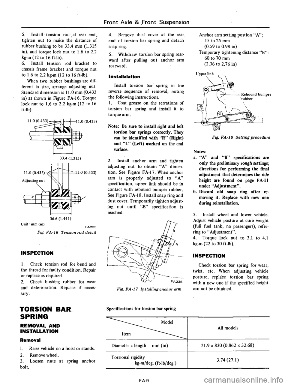
Install
anchor
arm
and
tighten
adjusting
nut
to
obtain
A
dimen
sion
See
Figure
F
A
17
When
anchor
arm
is
properly
adjusted
to
A
specification
upper
link
should
be
in
contact
with
rebound
bumper
rubber
See
Figure
FA
18
Install
snap
ring
and
dust
cover
Temporarily
tighten
adjust
ing
nut
until
B
specification
is
reached
I
I
I
FA236
Fig
FA
17
Installing
anchor
arm
Specifications
for
torsion
bar
spring
Diameter
x
length
mOl
in
Torsional
rigidity
kg
m
deg
ft
lb
deg
FA
9
Anchor
arm
setting
post
ion
A
ISt02Smm
0
59
to
0
98
in
Temporary
tightening
distance
B
60
to
70
mOl
2
36
to
2
76
in
UjPPje
Rebound
bumper
rubber
j
4W
Fig
FA
18
Setting
procedure
Notes
3
A
and
8
specifications
are
only
the
preliminary
rough
settings
directions
for
performing
the
final
adjustment
that
determines
the
ride
height
are
found
on
page
F
A
II
under
Adjustment
b
Discard
old
snap
ring
after
re
moving
it
Replace
with
new
one
during
reinstallation
3
Install
wheel
and
lower
vehicle
Adjust
vehicle
posture
at
curb
weight
full
fuel
tank
no
passengers
refer
ring
to
Adjustment
4
Torque
lock
nut
to
3
1
to
4
1
kg
m
22
to
30
ft
lb
INSPECTION
Check
torsion
bar
spring
for
wear
twist
etc
When
adjusting
vehicle
posture
replace
torsion
bar
spring
with
a
new
one
if
the
specified
height
can
not
be
obtained
All
models
21
9
x
830
0
862
x
32
68
3
74
27
I
Page 419 of 537

DESCRIPTION
REMOVAL
DESCRIPTION
The
fuel
tank
is4Sliters
II
Ji
U
s
gal
9
Ji
Imper
gal
in
capacity
The
tank
unit
is
mounted
to
the
right
side
of
the
rear
floor
1
Fuel
tank
2
Drain
plug
3
Filler
tube
4
RescfYOir
tank
5
Filler
hose
6
Breather
hose
7
Ventilation
hose
8
Evaporation
hose
9
Fuel
outlet
hose
and
tube
10
Fuel
tank
gauge
unit
11
Protector
12
Bracket
13
Retainer
14
Return
tube
Engine
Control
Fuel
Exhaust
Systems
FUEL
SYSTEM
CONTENTS
FE
4
FE
5
INSPECTION
INSTALLATION
FE
6
FE
6
The
filler
shutter
is
installed
to
the
filler
tube
on
California
models
The
electric
fuel
pump
is
adopted
on
air
conditioner
equipped
models
For
the
electric
fuel
pump
refer
to
Section
EF
FE194
Fig
FE
3
Fuel
tank
FE
4
Page 420 of 537
Detail
A
Detail
D
REMOVAL
Engine
Control
Fuel
Exhaust
Systems
Detail
Bn
4
Detail
e
@
Detail
E
B
Fuel
tank
See
Figure
FE
a
I
Disconnect
battery
ground
cable
2
Remove
drain
plug
and
receive
the
remaining
fuel
into
a
suitable
container
3
Disconnect
filler
tube
fro
filler
hose
4
Remove
fuel
tank
securing
bolts
5
Disconnect
two
ventilation
hoses
fuel
return
hose
and
fuel
outlet
hose
from
fuel
tank
6
Disconnect
fuel
tank
gauge
unit
wires
at
connector
7
Remove
fuel
tank
Note
Plug
hose
and
tube
opening
l
to
prevent
entry
of
dust
or
dirt
while
removing
ReservoIr
tank
1
Disconnect
battery
ground
cable
2
Disconnect
two
ventilation
hoses
evaporation
hose
and
breather
hose
3
Remove
reservoir
tank
securing
bolts
and
remove
tank
with
protector
Note
Plug
hose
and
tube
opening
l
to
prevent
entry
of
dust
or
dirt
while
removing
Fuel
tank
gauge
unit
Disconnect
battery
ground
cable
2
Disconnect
wires
from
fuel
tank
gauge
unit
3
Remove
fuel
tank
For
details
refer
to
fuel
tank
removal
4
Unit
gauge
is
a
bayonet
type
and
can
be
removed
by
turning
it
counter
clockwise
with
screwdriver
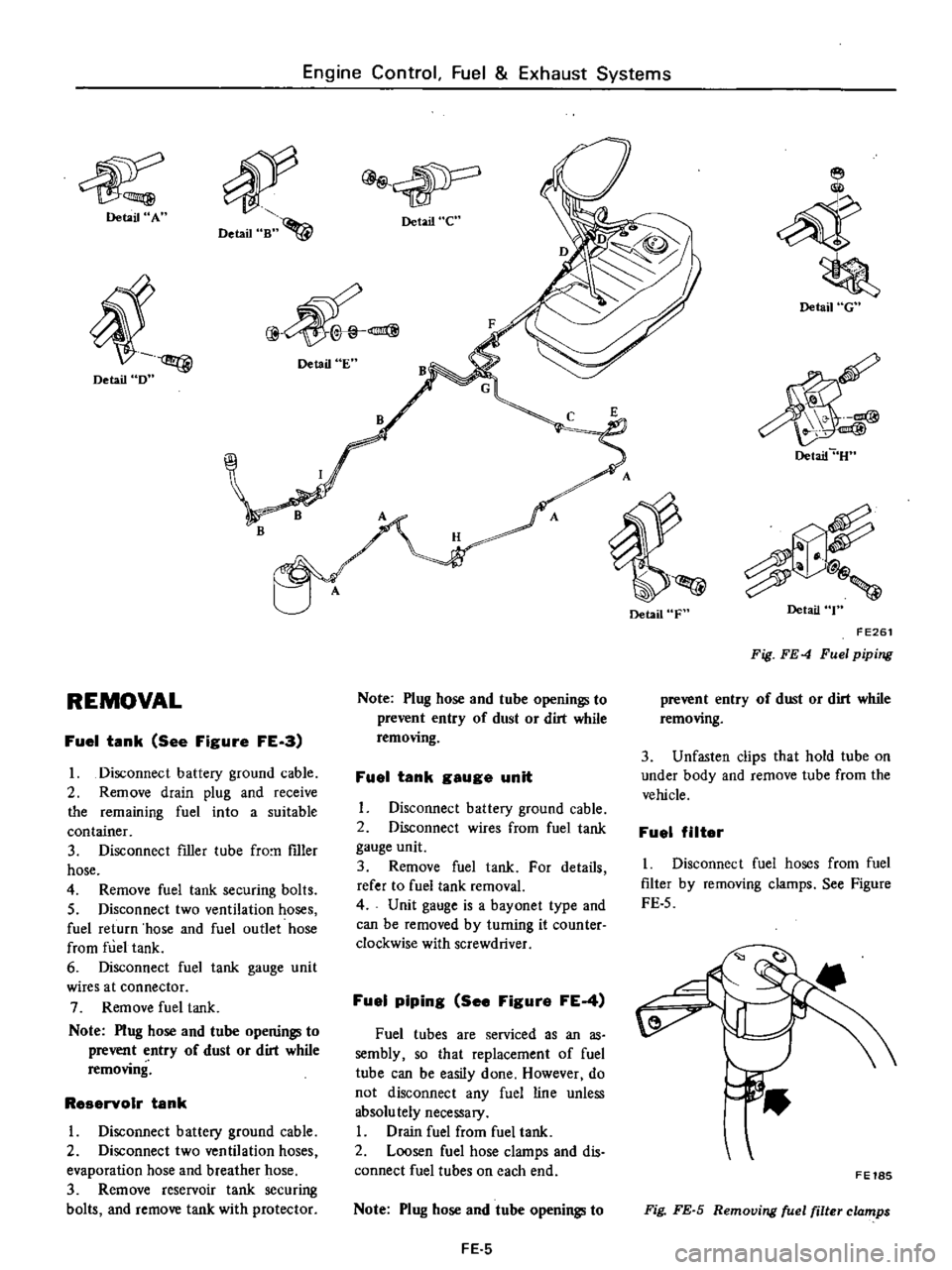
Fuel
piping
See
Figure
FE
4
Fuel
tubes
are
serviced
as
an
as
sembly
so
that
replacement
of
fuel
tube
can
be
easily
done
However
do
not
disconnect
any
fuel
line
unless
absolu
tely
necessary
I
Drain
fuel
from
fuel
tank
2
Loosen
fuel
hose
clamps
and
dis
connect
fuel
tubes
on
each
end
Note
Plug
hose
and
tube
openings
to
FE
5
Detail
F
Detail
G
Detail
U
Detail
T
FE261
Fig
FE
4
Fuel
piping
prevent
entry
of
dust
or
dirt
while
removing
3
Unfasten
clips
that
hold
tube
on
under
body
and
remove
tube
from
the
vehicle
Fuel
filter
I
Disconnect
fuel
hoses
from
fuel
filter
by
removing
clamps
See
Figure
FE
5
FE18S
Fig
FE
S
Removing
fuel
filter
clamps
Page 421 of 537
Engine
Control
Fuel
Exhaust
Systems
2
Remove
fuel
filter
INSPECTION
Fuel
tanle
Check
fuel
tank
for
cracks
or
deformation
If
necessary
replace
2
Fuel
hose
Inspect
all
hoses
for
cracks
fatigue
sweating
or
deterioration
Replace
any
hose
that
is
damaged
3
Fuel
tube
Replace
any
fuel
tube
that
is
crack
ed
rusted
collapsed
or
deformed
Note
Inspect
hoses
and
tubes
ac
cording
to
the
periodic
mainte
nance
schedule
4
Fuel
filter
Replace
fuel
filter
according
to
the
periodic
maintenance
schedule
or
when
it
is
clogged
or
restricted
DESCRIPTION
REMOVAL
DESCRIPTION
The
exhaust
systems
installed
on
the
non
California
models
differ
in
specifications
from
those
installed
on
the
California
models
Fuel
filter
is
of
a
cartridge
type
and
cannot
be
cleaned
Always
replace
with
a
new
one
5
Fuel
tank
gauge
unit
Check
gauge
unit
for
rust
deforma
tion
or
deterioration
If
necessary
replace
INSTALLATION
To
install
reverse
the
order
of
removal
Observe
the
following
I
Install
hose
clamps
securely
Do
not
tighten
excessively
to
avoid
damaging
hoses
2
Fasten
clips
holding
fuel
tube
on
under
body
securely
Failure
to
follow
this
caution
could
result
in
damage
to
the
surface
of
fuel
tube
3
Do
not
kink
or
twist
hose
and
tube
when
they
are
routed
EXHAUST
SYSTEM
CONTENTS
FE
6
FE
8
INSPECTION
INSTAllATION
Non
California
models
The
exhaust
system
consists
of
a
front
exhaust
tube
a
main
muffler
assembly
with
rear
tube
mounting
hangers
brackets
and
a
heat
insulator
FE
6
4
Install
fIller
hose
after
fuel
tank
has
been
mounted
in
place
Failure
to
follow
this
caution
could
result
in
leakage
from
around
hose
connections
5
When
installing
fuel
tank
gauge
unit
align
the
projection
of
tank
gauge
unit
with
the
notch
in
fuel
tank
and
tighten
it
securely
Be
sure
to
install
gauge
unit
with
O
ring
in
place
6
Run
engine
and
check
for
leaks
at
connections
Tightening
torque
Drain
plug
5
0
to
6
0
kg
m
36
to
43
ft
Ib
Fuel
tank
securing
bolt
0
8
to
1
I
kg
m
6
to
8
ft
Ib
Reservoir
tank
securing
bolt
032
to
0
44
kg
m
2
to
3
ft
Ib
FE
8
FE
8
California
models
The
exhaust
system
cOllsists
of
a
front
exhaust
tube
a
catalytic
conver
ter
assembly
a
center
tube
a
main
muffler
assembly
with
rear
tube
mounting
hangers
brackets
and
heat
insulators
The
catalytic
converter
is
COD
nected
to
the
front
tube
and
the
center
tube
with
bolts
and
nuts
Page 429 of 537
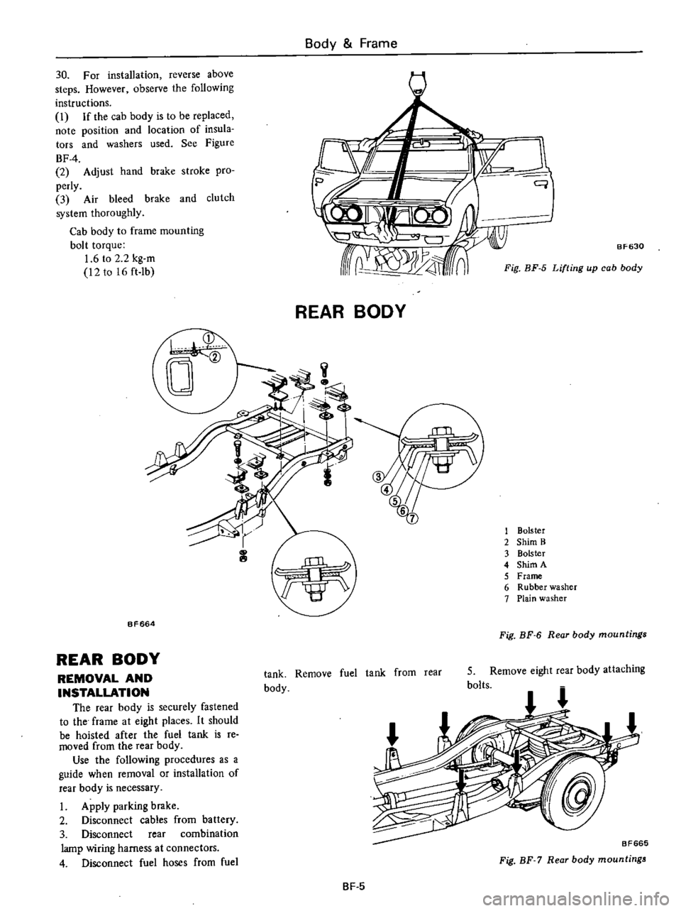
Body
Frame
30
For
installation
reverse
above
steps
However
observe
the
following
instructions
i
If
the
cab
body
is
to
be
replaced
note
position
and
location
of
insula
tors
and
washers
used
See
Figure
BF
4
2
Adjust
hand
brake
stroke
pro
perly
3
Air
bleed
brake
and
clutch
system
thorougWy
Cab
body
to
frame
mounting
bolt
torque
1
6
to
2
2
kg
m
12
to
16
ft
Ib
o
i
k
q
1Q
j
b
crru
V
J
8F630
rr
1
4
n
Fig
BF
5
Lifting
up
cab
body
REAR
BODY
1
Bolster
2
Shim
B
3
Bolster
4
Shim
A
5
Frame
6
Rubber
washer
7
Plain
washer
BF664
Fig
BF
6
Rear
body
mountings
REAR
BODY
REMOVAL
AND
INSTALLATION
The
rear
body
is
securely
fastened
to
the
frame
at
eight
places
It
should
be
hoisted
after
the
fuel
tank
is
re
moved
from
the
rear
body
Use
the
following
procedures
as
a
guide
when
removal
or
installation
of
rear
body
is
necessary
I
Apply
parking
brake
2
Disconnect
cables
from
battery
3
Disconnect
rear
combination
lamp
wiring
harness
at
connectors
4
Disconnect
fuel
hoses
from
fuel
tank
Remove
fuel
tank
from
rear
body
5
Remove
eight
rear
body
attaching
bolts
BF665
Fig
BF
7
Rear
body
mountings
BF
5
Page 461 of 537
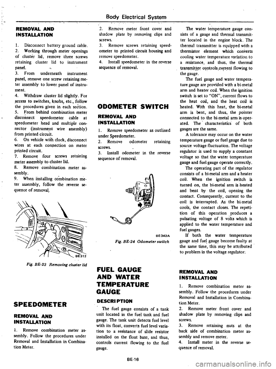
REMOVAL
AND
INSTALLATION
I
Disconnect
battery
ground
cable
2
Working
through
meter
openings
of
cluster
lid
remove
three
screws
retaining
cluster
lid
to
instrument
panel
3
From
underneath
instrument
panel
remove
one
screw
retaining
me
ter
assembly
to
lower
panel
of
instru
ment
4
Withdraw
cluster
lid
slightly
For
ccess
to
switches
knobs
etc
follow
the
procedures
given
in
each
section
5
From
behind
combination
meter
disconnect
speedometer
cable
at
speedometer
head
and
multiple
con
nector
instrume
nt
wire
assembly
from
printed
circuit
6
On
vehicle
with
clock
disconnect
wires
at
each
connection
on
meter
printed
circuit
7
Remove
four
screws
retaining
me
ter
assembly
to
cluster
lid
8
Remov
combination
meter
as
sembly
9
When
installing
combination
me
ter
assembly
follow
the
reverse
se
quence
of
removal
Fig
BE
23
Removing
eluster
lid
SPEEDOMETER
REMOVAL
AND
INSTALLATION
1
Remove
combination
meter
as
sembly
Follow
the
procedures
under
Removal
and
Installation
in
Combina
tion
Meter
Body
Electrical
System
2
Remove
meter
front
cover
and
shadow
plate
by
removing
clips
and
screws
3
Remove
screws
retaining
speed
ometer
to
printed
circuit
housing
and
remove
speedometer
4
Install
speedometer
in
the
reverse
sequence
of
removal
ODOMETER
SWITCH
REMOVAL
AND
INSTALLATION
I
Remove
speedometer
as
outlined
under
Speedometer
2
Remove
odometer
retaining
screws
3
Install
odometer
in
the
reverse
sequence
of
removal
BE342A
Fig
BE
24
Odometerswitch
FUEL
GAUGE
AND
WATER
TEMPERATURE
GAUGE
DESCRI
PTION
The
fuel
gauge
consists
of
a
tank
unit
located
in
the
fuel
tank
and
fuel
gauge
The
tank
unit
detects
fuel
level
with
its
float
converts
fuel
level
varia
tion
to
a
resistance
of
slide
resistor
installed
on
the
float
base
and
thus
controls
current
flowing
to
the
fuel
gauge
BE16
The
water
temperature
gauge
con
sists
of
a
gauge
and
thermal
transmit
ter
located
in
the
engine
block
The
thermal
transmitter
is
equipped
with
a
thermistor
element
which
converts
cooling
water
temperature
variation
to
a
resistance
and
thus
the
thermal
tr
t
c
rtrols
cUfTent
flowing
to
the
gauge
The
fuel
gauge
and
water
tempera
ture
gauge
are
provided
with
a
bi
metal
arm
and
heater
coil
When
the
ignition
switch
is
set
to
ON
current
flows
to
the
heat
coil
and
the
heat
coil
is
heated
With
this
heat
the
bi
metal
arm
is
bent
and
thus
the
pointer
connected
to
the
bi
metal
arm
is
oper
ated
The
characteristics
of
both
gauges
are
the
same
A
tolerance
may
occur
on
the
water
temperature
gauge
or
fuel
gauge
due
to
source
voltage
fluctuation
The
voltage
regulator
is
used
to
supply
a
constant
voltage
so
that
the
water
temperature
gauge
and
fuel
gauge
operate
correctly
The
operating
part
of
the
regulator
consists
of
a
bi
metal
arm
and
a
heater
coil
When
the
ignition
switch
is
turned
on
the
bi
metal
arm
is
heated
and
bent
by
the
coil
opening
the
contact
Consequently
current
to
the
coil
is
interrupted
As
the
bi
metal
cools
the
contact
closes
The
repeti
tion
of
this
operation
produces
a
pulsating
voltage
of
8
volts
which
is
applied
to
the
water
temperature
and
fuel
gauges
If
both
the
water
temperature
gauge
and
fuel
gauge
become
faulty
at
the
same
time
this
may
be
attributed
to
problem
in
the
voltage
regulator
REMOVAL
AND
INSTALLATION
1
Remove
combination
meter
as
sembly
Follow
the
procedures
under
Removal
and
Installation
in
Combina
tion
Meter
2
Remove
meter
front
cover
and
shadow
plate
by
removing
clips
and
screws
3
Remove
retaining
nuts
at
the
back
side
of
combination
meter
as
sembly
and
remove
meter
4
Install
meter
in
the
reverse
se
quence
of
removal