ground clearance DATSUN PICK-UP 1977 Service Manual
[x] Cancel search | Manufacturer: DATSUN, Model Year: 1977, Model line: PICK-UP, Model: DATSUN PICK-UP 1977Pages: 537, PDF Size: 35.48 MB
Page 176 of 537

L
0
5
to
0
8
mm
71j
Correct
2
Inspect
soldered
connection
of
armature
lead
and
commutator
If
loose
connection
is
found
solder
it
using
resin
flux
3
Armature
test
for
ground
Using
a
circuit
tester
place
one
test
probe
onto
armature
shaft
and
other
onto
each
commutator
bar
If
tester
shows
continuity
armature
is
grounded
and
must
be
replaced
EE022
Fig
EE
16
Testing
annature
for
ground
4
Check
armature
for
short
by
placing
it
on
armature
tester
growler
with
a
piece
of
iron
over
armature
core
rotating
armature
If
the
plate
vibrates
armature
is
shorted
j
l
EE023
Fig
EE
17
Testing
annature
for
ahort
Engine
Electrical
System
L
File
l
0
Commutator
Segmen
t
IWMica
Incorrect
EE021
Fig
EE
15
Undercutting
i118ulating
mica
5
Check
armature
for
continuity
by
placing
probes
of
tester
on
two
seg
ments
side
by
side
If
tester
shows
no
continuity
the
circuit
is
open
OVERRUNNING
CLUTCH
ASSEMBLY
Inspect
pinion
assembly
and
screw
sleeve
Screw
sleeve
must
slide
freely
along
armature
shaft
splines
If
damage
is
found
or
resistance
is
felt
when
sliding
it
must
be
repaired
Inspect
pinion
teeth
If
excessive
rub
bing
is
found
on
teeth
replace
Flywheel
ring
gear
also
must
be
in
spected
l
EE278
Fig
EE
18
Overrunning
clutch
auem
bly
BRUSH
HOLDER
TEST
FOR
GROUND
Using
a
circuit
tester
place
one
test
probe
onto
negative
side
of
brush
holder
and
another
onto
positive
side
If
tester
shows
continuity
brush
holder
is
shorted
to
ground
Replace
brush
holder
EE
9
Ee026
Fig
EE
19
Testing
brush
for
round
BEARING
METAL
Inspect
bearing
metal
for
wear
or
side
play
If
the
clearance
between
bearing
metal
and
armature
shaft
is
more
than
0
2
mm
0
0079
in
replace
metal
MAGNETIC
SWITCH
ASSEMBLY
1
Using
a
circuit
tester
l
check
con
tinuity
between
S
terminal
of
mag
netic
switch
and
switch
body
metal
If
continuity
does
not
exist
shunt
coit
is
opened
Replace
switch
assembly
2
In
the
same
manner
as
above
check
continuity
between
terminals
S
and
M
If
continuity
does
not
exist
series
coil
is
opened
Replace
switch
assembly
ASSEMBLY
Reassemble
starting
motor
in
re
verse
sequence
of
disassembly
When
assembling
be
sure
to
apply
grease
to
gear
case
and
rear
cover
bearing
metal
and
apply
oil
lightly
to
pinion
TEST
PERFORMANCE
TEST
Starter
motor
should
be
subjected
to
a
no
load
test
whenever
it
has
been
overhauled
to
ensure
that
its
performance
will
be
satisfactory
when
installed
on
engine
Starter
motor
should
also
be
subjected
to
the
test
when
the
cause
of
abnormal
operation
is
to
be
determined
A
brief
outline
of
the
test
is
given
below
Page 177 of 537

No
load
test
Connect
starting
motor
in
series
with
specified
12
volts
battery
and
an
ammeter
capable
of
indicating
1
000
amperes
Starter
motor
Diagnoses
of
test
1
Low
speed
with
no
load
and
high
current
draw
may
result
from
the
following
1
Tight
dirty
or
worn
bearings
2
Bent
armature
shaft
or
loosened
field
probe
3
Shorted
armature
Check
armature
further
4
A
grounded
armature
or
field
a
Remove
input
tenninal
b
Raise
two
negative
side
brushes
from
commutator
c
Using
a
circuit
tester
place
one
probe
onto
input
tenninal
and
the
other
onto
yoke
d
I
f
tester
indicates
continuity
raise
the
other
two
brushes
and
check
field
and
armature
separately
to
determine
whether
field
or
armature
is
grounded
2
F
allure
to
operate
with
high
current
draw
may
be
caused
by
the
Engine
Electrical
System
Specified
current
draw
and
revolu
tion
in
these
test
are
shown
in
Specifications
Switch
6
Battery
Et
Voltmeter
Ammeter
Ee026
Fig
EE
20
No
load
l
ting
following
I
A
grounded
or
open
field
coil
Inspect
the
connection
and
trace
circuit
with
a
circuit
tester
2
Armature
coil
does
not
operate
Inspect
commutator
for
excessive
burning
In
this
case
arc
may
occur
on
damaged
commutator
when
motor
is
operated
with
no
load
3
Burned
out
commutator
bar
Weak
brush
spring
tension
broken
brush
spring
rubber
bush
thrust
out
of
mica
in
commu
tat
or
or
a
loose
contact
between
biush
and
com
mutator
would
cause
commutator
bar
to
burn
3
Low
current
draw
and
low
no
load
speed
would
cause
high
internal
resistance
due
to
loose
con
nections
damaged
leads
dirty
corn
mutator
and
causes
listed
on
item
2
3
EE10
MAGNETIC
SWITCH
ASSEMBLY
TEST
Switch
o
Fv
IB
I
I
D
Battery
Starter
motor
EE351
FiN
EE
21
Circuit
ofmagndic
awitch
assembly
ted
If
the
starting
motor
check
is
OK
check
magnetic
switch
as
sembly
Connect
cables
between
negative
battery
tenninal
and
start
ing
motor
M
terminal
positive
battery
terminal
and
starting
motor
S
terminal
connecting
a
switch
in
series
as
shown
in
Figure
EE
21
With
the
switch
on
push
pinion
back
to
remove
all
slack
and
measure
the
clearance
l
between
pinion
front
edge
and
pinion
stopper
The
clearance
should
be
held
within
0
3
to
1
5
mm
0
012
to
0
059
in
If
neces
sary
adjust
it
by
changing
or
adding
adjusting
washer
s
Adjusting
washers
are
available
in
to
two
different
sizes
0
5
mm
0
020
in
and
O
S
mm
0
031
in
0
3
to
I
S
rom
0
012
to
0
059
in
l
EE029
Fig
EE
22
MeO
uring
clearance
t
Page 386 of 537

2
The
allowable
maximum
out
of
round
of
brake
drum
is
0
02
mm
0
0008
in
Re
condition
or
replace
brake
drum
if
specified
limit
is
exceeded
3
Measure
for
tapered
brake
drum
If
specified
limit
of
0
02
mm
0
0008
in
is
exceeded
as
measured
at
a
position
where
the
distance
of
4S
mm
177
in
is
kept
away
from
inlet
re
condition
or
replace
brake
drum
4
Contact
surface
with
which
linings
come
into
contact
should
be
finished
to
such
an
extent
that
it
is
ground
by
a
No
120
to
150
sand
paper
S
Using
a
drum
racer
finish
brake
drum
by
machining
if
it
shows
any
sign
of
score
marks
partial
wear
or
stepped
wear
on
its
contact
surface
Note
After
brake
drum
is
completely
re
conditioned
or
renewed
check
drum
and
shoes
for
proper
contact
pattern
Brake
assembly
I
When
brake
shoe
linings
are
cracked
incompletely
seated
uneven
Iy
worn
andlor
deteriorated
due
to
excessive
heating
or
soiled
with
oil
grease
and
brake
fluid
replace
2
Replace
linings
if
the
thickness
is
worn
down
to
less
than
1
0
mm
0
039
in
Note
When
brake
shoe
lining
is
in
stalled
grind
brake
shoe
lining
face
to
diameter
equal
to
that
of
brake
drum
lining
dimension
Width
x
Thickness
x
Length
4S
x
4
S
x
244
mm
1
77
x
0
177
x
9
61
in
3
Check
adjuster
for
smooth
oper
ation
4
Replace
shoe
return
springs
which
are
broken
or
fatigued
Brake
System
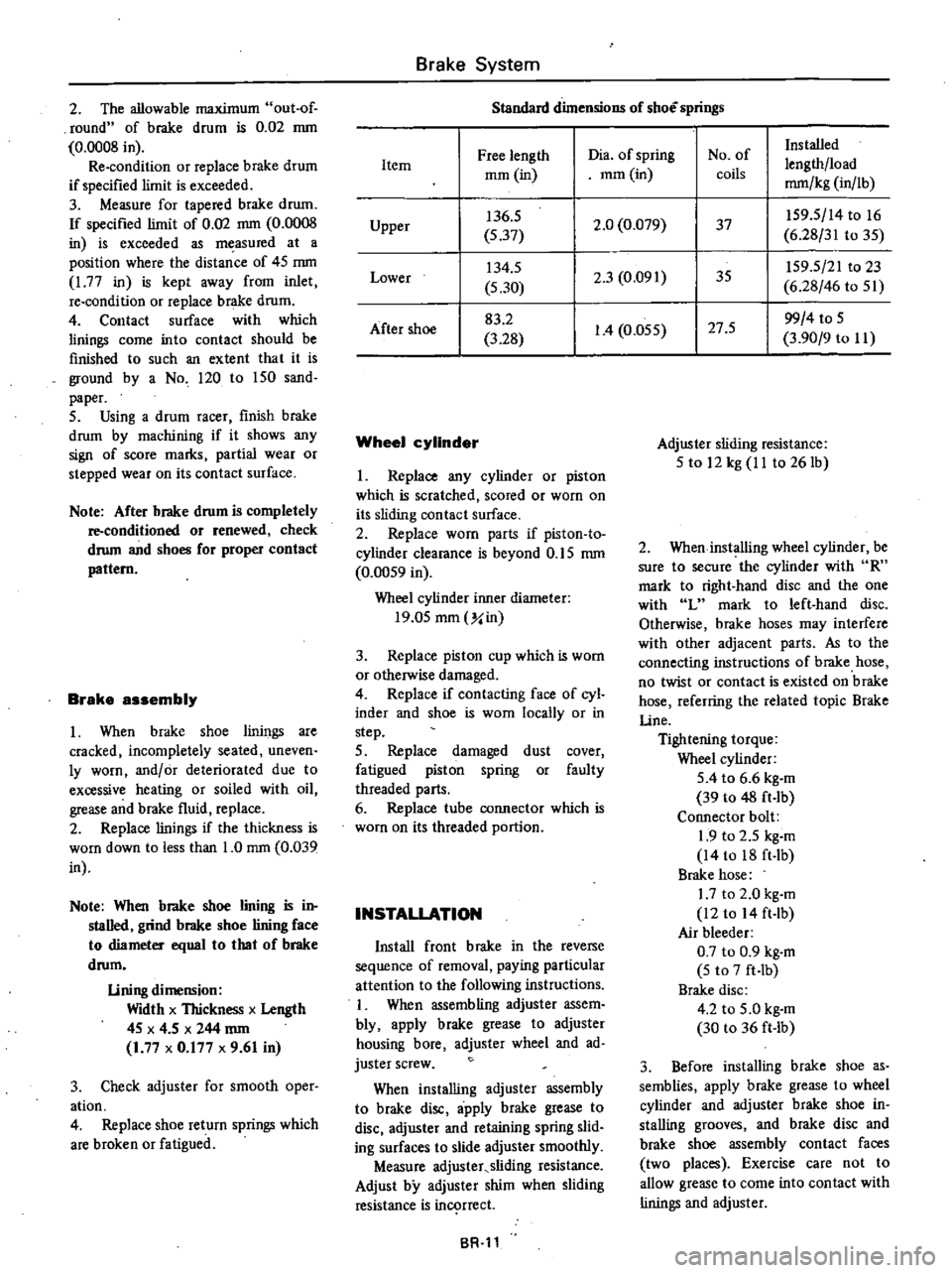
Standard
dimensions
of
shoe
springs
Free
length
Dia
of
spring
No
of
Installed
Item
lengthlload
mOl
in
mOl
in
coils
mm
kg
in
lb
Upper
136
5
2
0
0
079
37
IS9
S
14
to
16
S
37
6
28
31
to
3S
Lower
134
S
2
3
0
091
35
IS9
5
21
to
23
5
30
6
28
46
to
Sl
After
shoe
83
2
1
4
O
OSS
27
S
99
4
to
S
3
28
3
90
9
to
II
Wheel
cylinder
I
Replace
any
cylinder
or
piston
which
is
scratched
scored
or
worn
on
its
sliding
contact
surface
2
Replace
worn
parts
if
piston
to
cylinder
clearance
is
beyond
O
IS
mm
0
OOS9
in
Wheel
cylinder
inner
diameter
19
0S
mOl
Y
in
3
Replace
piston
cup
which
is
worn
or
otherwise
damaged
4
Replace
if
contacting
face
of
cyl
inder
and
shoe
is
worn
locally
or
in
step
S
Replace
damaged
dust
cover
fatigued
piston
spring
or
faulty
threaded
parts
6
Replace
tube
connector
which
is
worn
on
its
threaded
portion
INSTALLATION
Install
front
brake
in
the
reverse
sequence
of
removal
paying
particular
attention
to
the
following
instructions
I
When
assembling
adjuster
assem
bly
apply
brake
grease
to
adjuster
housing
bore
adjuster
wheel
and
ad
juster
screw
When
installing
adjuster
assembly
to
brake
disc
apply
brake
grease
to
disc
adjuster
and
retaining
spring
slid
ing
surfaces
to
slide
adjuster
smoothly
Measure
adjuster
sliding
resistance
Adjust
by
adjuster
shim
when
sliding
resistance
is
in
rrect
BR
ll
Adjuster
sliding
resistance
S
to
12
kg
II
to
261b
2
When
installing
wheel
cylinder
be
sure
to
secure
the
cylinder
with
R
mark
to
right
hand
disc
and
the
one
with
L
mark
to
left
hand
disc
Otherwise
brake
hoses
may
interfere
with
other
adjacent
parts
As
to
the
connecting
instructions
of
brake
hose
no
twist
or
contact
is
existed
on
brake
hose
referring
the
related
topic
Brake
line
Tightening
torque
Wheel
cylinder
SA
to
6
6
kg
m
39
to
48
ft
lb
Connector
bolt
1
9
to
2
5
kg
m
14
to
18
ft
Ib
Brake
hose
1
7
to
2
0
kg
m
12
to
14
ft
lb
Air
bleeder
0
7
to
0
9
kg
m
5
to
7
ft
Ib
Brake
disc
4
2
to
S
O
kg
m
30
to
36
ft
lb
3
Before
installing
brake
shoe
as
semblies
apply
brake
grease
to
wheel
cylinder
and
adjuster
brake
shoe
in
stalling
grooves
and
brake
disc
and
brake
shoe
assembly
contact
faces
two
places
Exercise
care
not
to
allow
grease
to
come
into
contact
with
linings
and
adjuster
Page 524 of 537

2
Install
the
clutch
assembly
on
the
crankshaft
Note
Key
should
be
set
on
crank
shaft
before
installing
clutch
assem
bly
3
Using
Clutch
Spanner
Wrench
hold
clutch
hub
With
socket
wrench
secure
clutch
hub
securing
bolt
Tightening
torque
Clutch
hub
securing
bolt
1
5
kg
m
II
ft
lb
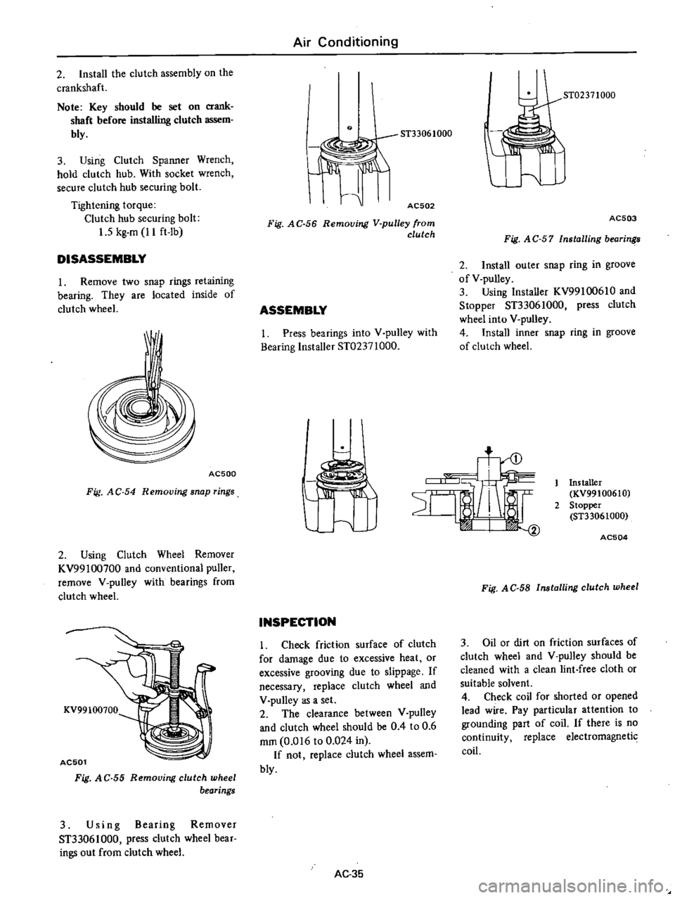
DISASSEMBLY
1
Remove
two
snap
rings
retaining
bearing
They
are
located
inside
of
clutch
wheel
AC500
Fig
AC
54
Removing
snap
rings
2
Using
Clutch
Wheel
Remover
KV99100700
and
conventional
puller
remove
V
pulley
with
bearings
from
clutch
wheel
KV99100700
AC501
Fig
A
C
55
Removing
clutch
wheel
bearings
3
Using
Bearing
Remover
ST33061000
press
clutch
wheel
bear
ings
out
from
clutch
wheel
Air
Conditioning
9
AC502
Fig
AC
56
Removing
V
pulley
from
clutch
ASSEMBLY
I
Press
bearings
into
V
pulley
with
Bearing
Installer
ST02371000
ST02371000
AC503
Fig
A
C
57
Installing
bearin
2
Install
outer
snap
ring
in
groove
of
V
pulley
3
Using
Installer
KV99100610
and
Stopper
ST33061000
press
clutch
wheel
into
V
pulley
4
Install
inner
snap
ring
in
groove
of
clutch
wheel
t
INSPECTION
Check
friction
surface
of
clutch
for
damage
due
to
excessive
heat
or
excessive
grooving
due
to
slippage
If
necessary
replace
clutch
wheel
and
V
pulley
as
a
set
2
The
clearance
between
V
pulley
and
clutch
wheel
should
be
0
4
to
0
6
mm
0
016
to
0
024
in
If
not
replace
clutch
wheel
assem
bly
AC
35
Installer
KV99100610
2
Stopper
ST33061000
AC504
Fig
AC
58
Installing
clutch
wheel
3
Oil
or
dirt
on
friction
surfaces
of
clutch
wheel
and
V
pulley
should
be
cleaned
with
a
clean
lint
free
cloth
or
suitable
solvent
4
Check
coil
for
shorted
or
opened
lead
wire
Pay
particular
attention
to
grounding
part
of
coil
If
there
is
no
continuity
replace
electromagnetic
coil