service interval DATSUN PICK-UP 1977 Service Manual
[x] Cancel search | Manufacturer: DATSUN, Model Year: 1977, Model line: PICK-UP, Model: DATSUN PICK-UP 1977Pages: 537, PDF Size: 35.48 MB
Page 95 of 537

r
direction
when
hoses
are
assembled
3
Ensure
that
clearance
between
radiator
hose
and
any
adjacent
parts
is
30
mm
I
181
in
minimum
On
mod
els
equipped
with
air
conditions
a
minimum
clearance
of
18
mm
0
709
in
should
exist
between
compressor
and
hose
4
Ensure
that
clearance
between
shroud
and
fan
is
even
at
any
place
Note
Be
careful
not
to
damage
radia
tor
fins
and
core
tube
when
in
stalling
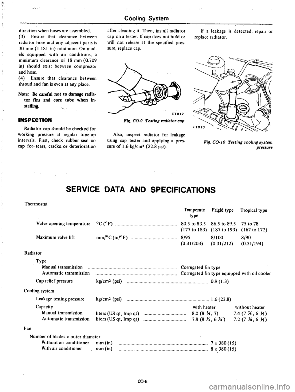
INSPECTION
Radiator
cap
should
be
checked
for
working
pressure
at
regular
tune
up
intervals
First
check
rubber
seal
on
cap
for
tears
cracks
or
deterioration
Cooling
System
after
cleaning
it
Then
install
radiator
cap
on
a
tester
If
cap
does
not
hold
or
will
not
release
at
the
specified
pres
sure
replace
cap
Fig
CO
9
Telting
radiator
cap
Also
inspect
radiator
for
leakage
using
cap
tester
and
applying
a
pres
sure
of
1
6
kg
cm
22
8
psi
If
a
leakage
is
detected
repair
or
replace
radiator
Fig
CO
IO
Testing
cooling
6ystem
pUS
ure
SERVICE
DATA
AND
SPECIFICATIONS
Thermostat
Valve
opening
temperature
oC
F
Maximum
valve
lift
mm
oC
inj
F
Radia
tor
Type
Manual
transmission
Automatic
transmission
Cap
relief
pressure
Cooling
system
Leakage
testing
pressure
Capacity
Manual
transmission
Automatic
transmission
Fan
Number
of
blades
x
outer
diameter
Without
air
conditioner
mm
in
With
air
conditioner
mm
in
kg
em
psi
kg
em
psi
liters
US
qt
Imp
qt
liters
US
qt
Imp
qt
CO
6
Temperate
Frigid
type
Tropical
type
type
80
5
to
83
5
86
5
to
89
5
75
to
78
177
to
183
187
to
193
167
to
172
8
95
8
100
8
90
0
31
203
0
31
212
0
31
194
Corrugated
fin
type
Corrugated
fin
type
equipped
with
oil
cooler
0
9
1
3
1
6
22
8
with
heater
8
0
8
Ii
7
7
8
8
Y
6
J
i
without
heater
74
7J
i6
1i
7
2
7
X
6
X
7
x
380
15
8
x
380
15
Page 505 of 537

3
Piping
Flared
section
of
high
pressure
and
low
pressure
flexible
hose
Pipe
connections
rvice
valve
4
Evaporator
housing
Jnlet
and
outlet
pipe
connections
Expansionvalve
ELECTRIC
LEAK
DETECTOR
for
the
operational
procedures
refer
to
the
instructions
furnished
with
each
electric
leak
detector
Amount
of
refrigerant
Air
Conditioning
REFRIGERANT
LEVEL
CHECK
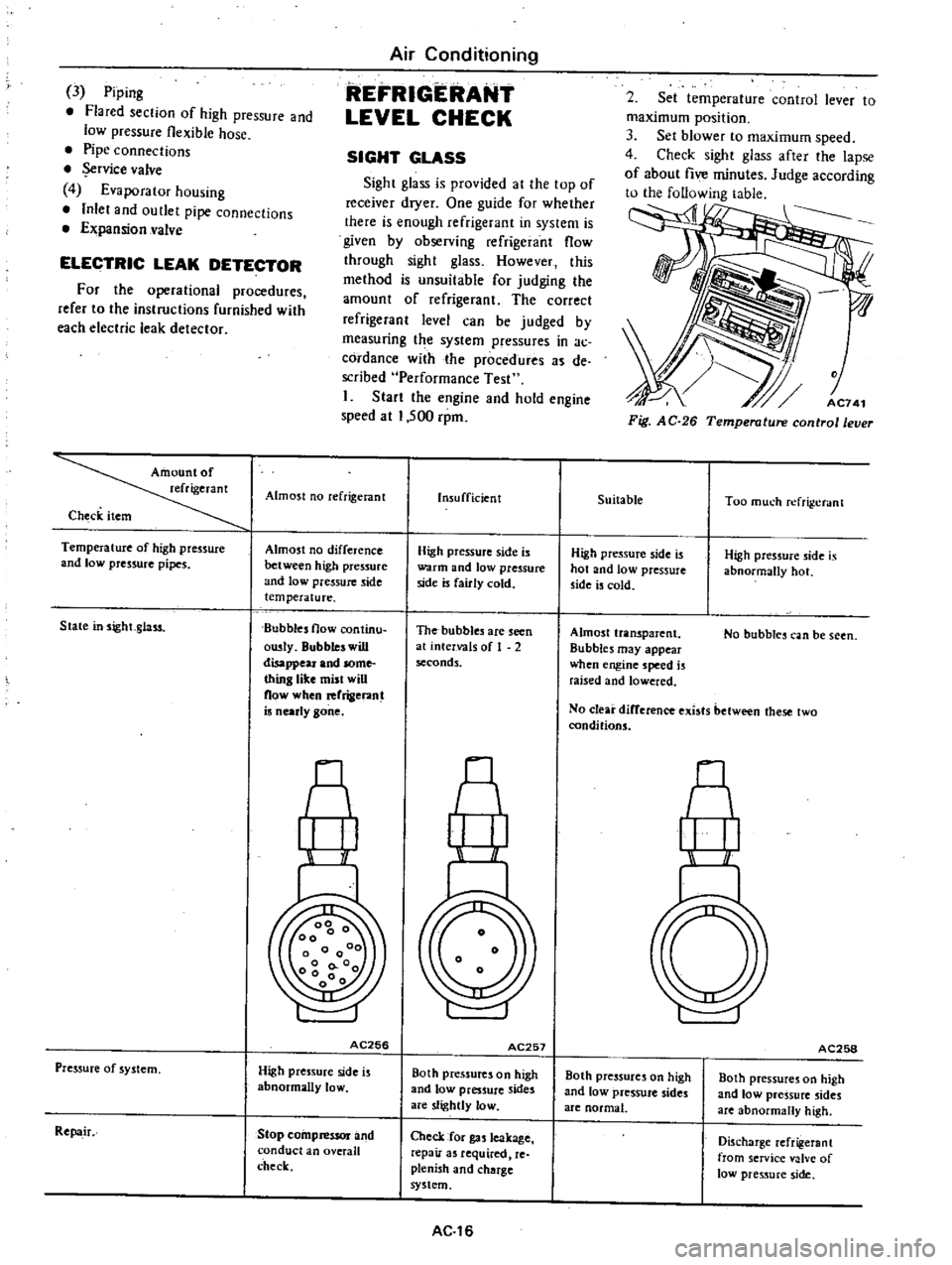
SIGHT
GLASS
Sight
glass
is
provided
at
the
top
of
receiver
dryer
One
guide
for
whether
there
is
enough
refrigerant
in
system
is
given
by
observing
refrigerant
flow
through
sight
glass
However
this
method
is
unsuitable
for
judging
the
amount
of
refrigerant
The
correct
refrigerant
level
can
be
judged
by
measuring
t
e
system
pressures
in
ac
cordance
with
the
procedures
de
scribed
Performance
Test
I
Start
the
engine
and
hold
engine
speed
at
1
500
rpm
Almost
no
reftigerant
Check
item
Temperature
of
high
pressure
and
low
pressure
pipes
Almost
no
difference
between
high
pressure
and
low
pressure
side
temperature
Bubbles
flow
continu
ousty
Bubbles
will
disappeu
a
nd
some
thing
like
mist
will
now
when
rerrigeran
is
nearly
gone
State
insightglass
A
I
I
AC256
Pressure
of
system
High
pressure
side
is
abnormally
loW
Repa
ir
Stop
compressor
and
conduct
an
overall
check
Insufficient
High
pressure
side
is
warOl
and
low
pressure
side
is
fairly
cold
The
bubbles
are
seen
at
intervals
of
1
2
seconds
A
r
I
AC257
Both
pressures
on
high
and
low
preS
ure
sides
are
slightly
low
Check
for
gas
leakage
repair
as
required
re
plenish
and
charge
system
AC
16
2
Set
temperature
control
lever
to
maximum
position
3
Set
blower
to
maximum
speed
4
Check
sight
gla
after
the
lapse
of
about
five
minutes
Judge
according
to
the
following
table
AC741
Fig
AC
26
Temperature
control
lever
Suitable
Too
much
refri
crant
High
pressure
side
is
hot
and
low
pressure
side
is
cold
High
pressure
side
is
abnormally
hot
Almost
transparent
Bubbles
may
appear
when
engine
speed
is
raised
and
lowered
No
bubbles
can
be
seen
No
clear
difference
exists
between
these
two
conditions
M
II
I
AC258
Both
pressures
on
high
and
low
pressure
sides
are
normal
Both
pressures
on
high
and
low
pressure
sides
are
abnormally
high
Discharge
reft
gerant
from
service
valve
of
10
11
pressure
side