oil change DATSUN PICK-UP 1977 Service Manual
[x] Cancel search | Manufacturer: DATSUN, Model Year: 1977, Model line: PICK-UP, Model: DATSUN PICK-UP 1977Pages: 537, PDF Size: 35.48 MB
Page 11 of 537
General
Information
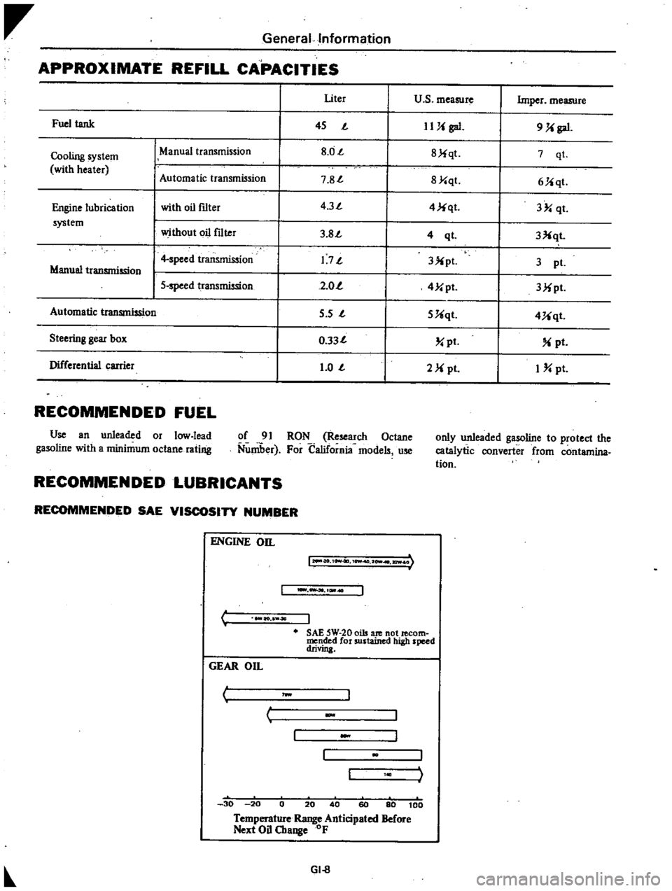
APPROXIMATE
REFILL
CAPACITIES
I
Uter
u
s
measure
Imper
measure
Fuel
tank
I
45
J
IUi
gal
9
Ji
gal
Cooling
system
ManUal
transmission
I
8
0J
I
8Jiqt
7
qt
with
heater
Automatic
tr
smission
I
7
8J
I
8Y
qt
6Jiqt
Engine
lubrication
with
oil
f1lter
I
4
3J
I
4
Ji
qt
3
qt
system
without
oil
f1lter
I
3
8J
I
3Xqt
4
ql
I
4
speed
transmission
I
1
7J
I
3X
pl
3
pI
Manual
transmission
I
5
speed
transmission
I
2
0
I
4Y
pt
3Mpt
Automatic
transmission
I
5
s
J
I
5Uqt
4Uqt
Steering
gear
box
I
0
33J
I
pt
pt
Differential
carrier
I
1
0
J
I
2M
pI
I
pt
RECOMMENDED
FUEL
Use
an
unleaded
or
low
lead
gasoline
with
a
minimum
octane
rating
of
91
RON
Research
Octane
Nuniber
For
California
models
use
only
unleaded
gasoline
to
protect
the
catalytic
converter
from
contamina
tion
RECOMMENDED
LUBRICANTS
RECOMMENDED
SAE
VISCOSITY
NUMBER
C
ENGINE
on
12O
II
O
10Vt4ll
10Wf
2
I
ICWI
I
ao
40
J
SAE
5W
20
oils
ate
not
lecom
mended
for
sustained
high
speed
drivin
GEAR
On
I
J
w
c
30
20
0
20
40
60
80
100
Temperature
Range
Anticipated
Before
Next
Oil
Change
OF
GI
8
Page 20 of 537
r
ManifolJ
nuts
I
2
to
1
6
kg
m
8
7
to
I
6
ft
lb
Carburelor
nuls
0
5
to
1
0
kg
m
3
6
to
7
2
fl
tb
Fig
ET
7
Tightening
s
quence
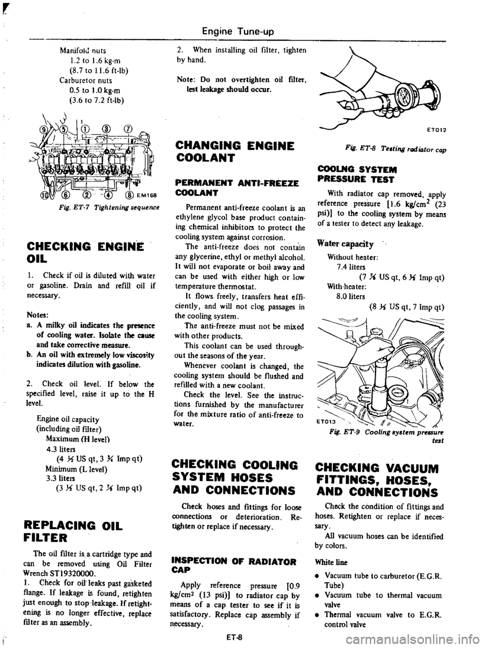
CHECKING
ENGINE
OIL
Check
if
oil
is
diluled
with
water
or
gasoline
Drain
and
refill
oil
if
necessary
Notes
a
A
milky
oil
indicates
the
presence
of
cooling
water
Isolate
the
cause
and
take
corrective
measure
b
An
oil
with
extremely
low
viscosity
indicates
dilution
with
gasoline
2
Check
oil
level
If
below
the
specified
level
raise
it
up
10
the
H
level
Engine
oil
capacity
including
oil
filter
Maximum
H
leven
4
3
liters
4
MUS
qt
3
Y
Imp
qt
Minimum
L
level
3
3
liters
3
f
US
qt
2
U
Imp
ql
REPLACING
OIL
FILTER
The
oil
mter
is
a
cartridge
type
and
can
be
removed
using
Oil
Filter
Wrench
STI9320000
I
Check
for
oil
leaks
past
gasketed
flange
If
leakage
is
found
retighten
just
enough
to
stop
leakage
If
retight
ening
is
no
longer
effective
replace
mter
as
an
assembly
Engine
Tune
up
2
When
installing
oil
filter
tighlen
by
hand
Note
Do
not
overtighten
oil
flIt
lest
leakage
should
occur
CHANGING
ENGINE
COOLANT
PERMANENT
ANTI
FREEZE
COOLANT
Permanent
anti
freeze
coolant
is
an
ethylene
glycol
base
producl
conlain
ing
chemical
inhibilors
10
protect
the
cooling
system
against
corrosion
The
anti
freeze
does
not
contain
any
glycerine
ethyl
or
methyl
alcohol
It
will
not
evaporate
or
boil
away
and
can
be
used
with
either
high
or
low
temperaturethennoslat
It
flows
freely
transfers
heat
effi
ciently
and
will
not
clog
passages
in
the
cooling
system
The
anti
freeze
must
not
be
mixed
with
other
products
This
coolant
can
be
used
through
out
the
seasons
of
the
year
Whenever
coolant
is
changed
the
cooling
syslem
should
be
flushed
and
refilled
with
a
new
coolant
Check
the
level
See
the
instruc
lions
furnished
by
the
manufacturer
for
the
mixture
ratio
of
anti
freeze
10
water
CHECKING
COOLING
SYSTEM
HOSES
AND
CONNECTIONS
Check
hoses
and
fittings
for
loose
connections
or
deterioration
Re
tighten
or
replace
if
necessary
INSPECTION
OF
RADIATOR
CAP
Apply
reference
pressure
0
9
kg
cm2
13
psi
1
to
radiator
cap
by
means
of
a
cap
tester
to
see
if
it
is
satisfactory
Replace
cap
assembly
if
necessary
ET
8
Fig
ET
fJ
Teltill
l
rod
ioto
cop
COOLNG
SYSTEM
PRESSURE
TEST
With
radiator
cap
removed
apply
reference
pressure
1
6
kg
cm2
23
psi
to
the
cooling
system
by
means
of
a
lesler
to
detect
any
leakage
Water
capacity
Without
heater
7
4
liters
7
U
US
qt
6
f
Imp
qt
With
heater
8
0
liters
8
f
US
qt
7
Imp
qt
CHECKING
VACUUM
FITTINGS
HOSES
AND
CONNECTIONS
Check
the
condition
of
filtings
and
hoses
Retighten
or
replace
if
neces
sary
All
vacuum
hoses
can
be
identified
by
colors
White
line
Vacuwn
tube
to
carburetor
E
G
R
Tube
Vacuum
tube
to
thermal
vacuum
valve
Thennal
vacuum
valve
to
E
G
R
control
valve
Page 40 of 537

Engine
Tune
up
Condition
Probable
cause
Low
or
no
current
Ign
tion
system
out
of
order
Burned
distributor
point
Improper
point
gap
Faulty
condenser
Leak
at
rotor
cap
and
rotor
Faulty
spark
plug
Improper
ignition
timing
Faulty
ignition
coil
Disconnection
of
high
tension
cable
Loose
connection
or
disconnection
in
primary
circuit
Fuel
system
out
of
order
Lack
offuel
Dirty
fuel
strainer
Dirty
or
clogged
fuel
pipe
Fuel
pump
will
not
work
properly
Carburetor
choke
will
not
work
properly
Improper
adjustment
of
float
level
Improper
idling
Dirty
or
clogged
carburetor
Clogged
breather
pip
of
fuel
tank
Malfunctioning
an
ti
dieseling
solenoid
valve
Incorrect
sparle
plug
tightening
or
faulty
gasket
Improper
grade
engine
oil
or
low
viscosity
Incorrect
valve
clearance
Compression
leak
from
valve
seat
Sticky
valve
stem
Weak
or
damaged
valve
springs
Compression
leak
at
cylinder
head
gasket
Sticking
or
damaged
piston
ring
Worn
piston
ring
or
cylinder
Trouble
ooting
procedure
Pour
the
engine
oil
from
plug
hole
and
then
measure
cylinder
compression
Compression
increases
Compression
does
not
change
Low
comp
ion
ET
28
Corrective
action
Check
for
loose
terminal
or
disconnection
in
primary
circuit
Check
for
burned
points
Repair
or
replace
Adjust
Replace
Clean
or
replace
aean
adjust
plug
gap
or
replace
Adjust
Replace
Replace
Repair
or
replace
Supply
Replace
Clean
Repair
or
replace
Check
and
adjust
Correct
Adjust
Disassemble
and
clean
Repair
and
clean
Check
for
loose
terminal
or
wire
harness
Tighten
to
normal
torque
or
replace
gasket
Replace
with
proper
grade
oil
Adjust
Remove
cyljnder
head
and
lap
valves
Correct
or
replace
valve
and
valve
guide
Replace
valve
springs
Replace
gasket
Replace
piston
rings
Overhaul
engine
Malfunctiong
cylinder
or
piston
ring
Compression
leaks
from
valve
cylinder
head
or
head
gasket
Except
transistor
ignition
system
Page 43 of 537
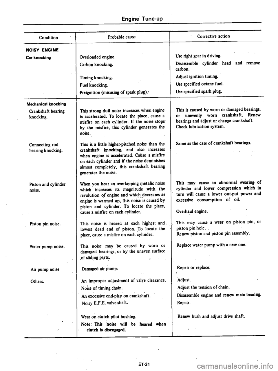
Condition
NOISY
ENGINE
Car
knocking
Mechanical
knocking
Crankshaft
bearing
Imocking
Connecting
rod
bearing
knocking
Piston
and
cylinder
noise
Piston
pin
noise
Water
pump
noise
Air
pump
noise
Others
Engine
Tune
up
Probable
cause
Overloaded
engine
Carbon
knocking
Timing
knocking
Fuel
knocking
Preignition
misusing
of
spark
plug
This
strong
dull
noise
increases
when
engine
is
accelerated
To
locate
the
place
cause
a
misfire
on
each
cylinder
If
the
noise
stops
by
the
misfire
this
cylinder
generates
the
noise
This
is
a
little
higher
pitched
noise
than
the
crankshaft
Imocking
and
also
increases
when
engine
is
accelerated
Cause
a
misfire
on
each
cylinder
and
if
the
noise
deminishes
almost
completely
this
crankshaft
bearing
generates
the
noise
When
you
hear
an
overlapping
metalic
noise
which
increases
its
magnitude
with
the
revolution
of
engine
and
which
decreases
as
engine
is
warmed
up
this
noise
is
caused
by
piston
and
cylinder
To
locate
the
place
cause
a
misfire
on
each
cylinder
This
noise
is
heared
at
each
highest
and
lowest
dead
end
of
piston
To
locate
the
place
cause
a
misfire
on
each
cylinder
This
noise
may
be
caused
by
worn
or
damaged
earings
or
by
the
uneven
surface
of
sliding
parts
Damaged
air
pump
An
improper
adjustment
of
valve
clearance
Noise
of
timing
chain
An
excessive
end
play
on
crankshaft
Noisy
E
F
E
valve
shaft
Wear
on
clutch
pilot
bushing
Note
This
noise
will
be
heared
when
clutch
is
disengaged
ET31
Corrective
action
Use
right
gear
in
driving
Disassemble
cylinder
head
and
remove
carbon
Adjust
ignition
timing
Use
specified
octane
fuel
Use
specified
spark
plug
This
is
caused
by
worn
or
damaged
bearings
or
unevenly
worn
crankshaft
Renew
bearings
and
adjust
or
change
crankshaft
Check
lubrication
system
Same
as
the
case
of
crankshaft
bearings
This
may
cause
an
abnormal
wearing
of
cylinder
and
lower
compression
which
in
turn
will
cause
a
lower
out
put
power
and
excessive
consumption
of
oil
Overhaul
engine
This
may
cause
a
wear
on
piston
pin
or
piston
pin
hole
Renew
piston
and
piston
pin
assembly
Replace
water
pump
with
a
new
one
Repair
or
replace
Adjust
Adjust
the
tension
of
chain
Disassemble
engine
and
renew
main
bearing
Repair
Renew
bush
and
adjust
drive
shaft
Page 45 of 537

Condition
POOR
FUEL
ECONOMY
Se
the
xplanation
of
the
pow
r
dec
Oth
n
PROBLEM
IN
OTHER
FUNCTIONS
D
cr
d
oil
p
ssure
Excessive
wear
on
the
sliding
parts
Scuffing
of
sliding
parts
Floor
temperature
too
high
California
only
Engine
Tune
up
Probable
cause
Exceeding
idling
revolution
Inoperative
acceleration
recovery
Fuel
leakage
Malfunction
of
B
C
D
D
Malfunction
of
A
r
C
air
cleaner
Inadequate
oil
quality
Overheat
Worn
oil
pump
regulator
valve
Functional
deterioration
of
oil
pump
Blocked
oil
f1lter
Increased
clearance
in
various
sliding
parts
Blocked
oil
strainer
Inoperative
oil
gauge
pressure
switch
Oil
pressure
decreases
Improper
quality
or
contamination
of
oil
Damaged
air
cleaner
Overheat
or
overcoal
Improper
fuel
mixture
Decrease
of
oil
pressure
Insufficient
clearances
Overhea
t
Improper
fuel
mixture
Problem
in
fuel
system
Refer
to
Inspec
tion
of
Fuel
System
Problem
in
ignition
system
Refer
to
In
spection
of
Ignition
System
ET33
Corrective
action
Adjust
it
to
the
designated
rpm
Adjust
it
Repair
or
tighten
the
connection
of
fuel
pipes
Adjust
Check
and
replace
Use
the
designated
oil
Previously
mentioned
Disassemble
oil
pump
and
repair
or
renew
it
Repair
or
replace
it
with
a
new
one
Renew
it
Disassemble
and
replace
the
worn
parts
with
new
ones
Oeanit
Replace
it
with
a
new
one
Previousiy
mentioned
Exchange
the
oil
with
proper
one
and
change
element
Change
elemen
t
Previously
mentioned
Check
the
fuel
system
Previously
mentioned
Readjust
to
the
designated
clearances
Previously
mentioned
Check
the
fuel
system
Check
and
repair
Check
and
repair
Page 67 of 537
5
Install
rocker
arms
by
pressing
valve
springs
down
with
a
screwdriver
6
Install
valve
rocker
springs
7
After
assembling
cylinder
head
turn
camshaft
until
No
I
piston
is
at
T
D
C
on
its
compression
stroke
EM1S5
Fig
EM
83
A
embling
cylinder
head
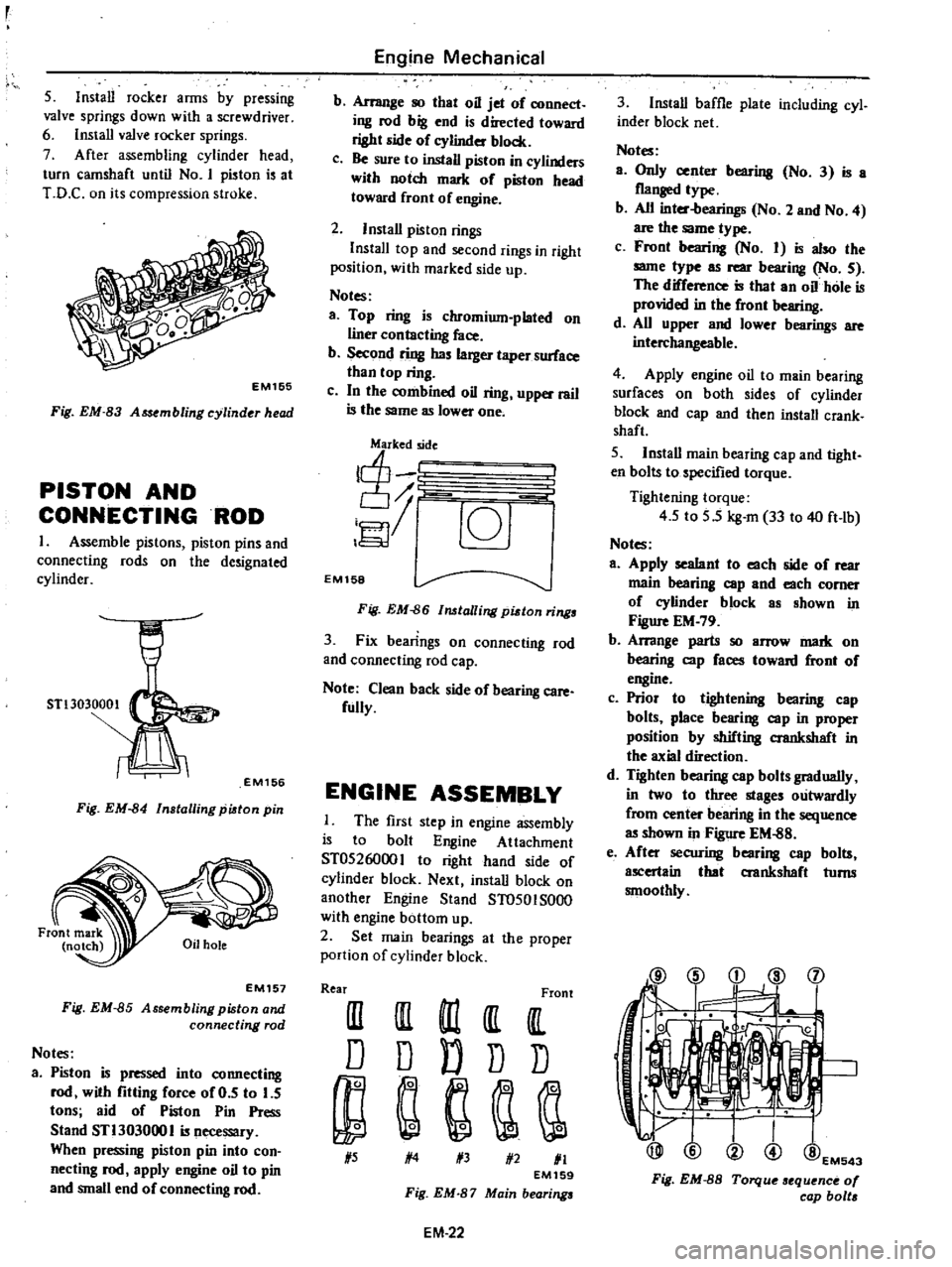
PISTON
AND
CONNECTINGROD
1
Assemble
pistons
piston
pins
and
connecting
rods
on
the
de
ignated
cylinder
STl3030001
EM156
Fig
EM
84
Installing
piston
pin
EM157
Fig
EM
85
Assembling
piston
and
connecting
rod
Notes
a
Piston
is
pressed
into
connecting
rod
with
fitting
force
of
0
5
to
5
tons
aid
of
Piston
Pin
Press
Stand
STl303000
I
is
necessary
When
pressing
piston
pin
into
con
necting
rod
apply
engine
oil
to
pin
and
small
end
of
connecting
rod
Engine
Mechanical
b
Arrange
so
that
oil
jet
of
connect
ing
rod
big
end
is
directed
toward
right
side
of
eylinder
block
c
Be
sure
to
install
piston
in
cylinders
with
notch
mark
of
piston
head
toward
front
of
engine
2
Install
piston
rings
InstalI
top
and
second
rings
in
right
position
with
marked
side
up
Notes
a
Top
ring
is
chromium
plated
on
liner
contacting
face
b
Second
ring
has
larger
taper
surface
than
top
ring
c
In
the
combined
oil
ring
upper
rail
is
the
same
as
lower
one
j
c6J
EM158
Fig
EM
86
lalling
pidon
rings
3
Fix
bearings
on
connecting
rod
and
connecting
rod
cap
Note
Clean
back
side
of
bearing
care
fully
ENGINE
ASSEMBLY
The
first
step
in
engine
assembly
is
to
bolt
Engine
Attachment
ST0526000
I
to
right
hand
ide
of
cylinder
block
Next
install
block
on
another
Engine
Stand
ST0501S000
with
engine
bottom
up
2
Set
main
bearings
at
the
proper
portion
of
cylinder
block
Rear
Front
III
III
m
It
IlL
D
D
D
D
D
1
5
1
4
1
3
1
2
1
1
EM159
Fig
EM
87
Main
bearings
EM
22
3
Install
baffle
plate
including
cyl
inder
block
net
Notes
a
Only
center
bearing
No
3
is
a
flanged
type
b
All
inter
bearings
No
2
and
No
4
are
the
same
type
c
Front
bearing
No
I
is
also
the
same
type
as
rear
bearing
No
5
The
difference
is
that
an
oil
hole
is
provided
in
the
front
bearing
d
All
upper
and
lower
bearings
are
interchangeable
4
Apply
engine
oil
to
main
bearing
surfaces
on
both
sides
of
cylinder
block
and
cap
and
then
install
crank
shaft
5
Install
main
bearing
cap
and
tight
en
bolts
to
specified
torque
Tightening
torque
4
5
to
5
5
kg
m
33
to
40
ft
lb
Notes
a
Apply
sealant
to
each
side
of
rear
main
bearing
cap
and
each
comer
of
eylinder
block
as
shown
in
Figure
EM
79
b
Arrange
parts
so
arrow
mark
on
bearing
cap
faces
toward
front
of
engine
c
Prior
to
tightening
bearing
cap
bolts
place
bearing
cap
in
proper
position
by
shifting
crankshaft
in
the
axial
direction
d
Tighten
bearing
cap
bolts
gradually
in
two
to
three
stages
outwardly
from
center
bearing
in
the
sequence
as
shown
in
Figure
EM
88
e
After
securing
bearing
cap
bolts
ascertain
that
aankshaft
turns
smoothly
@
i
d
l
j
1
@EM543
Fig
EM
8S
Torque
sequence
0
cap
bolt
Page 93 of 537
REMOVAL
AND
INSTALLATION
To
replace
the
torque
coupling
follow
the
same
procedure
as
in
the
water
pump
The
torque
coupling
can
not
be
separated
from
the
water
pump
Cooling
System
DISASSEMBLY
The
torque
coupling
is
so
designed
that
it
can
not
be
disassembled
INSPECTION
Inspect
torque
coupling
for
oil
leakage
If
necessary
replace
TEM
COUPLl
G
For
air
conditioner
equipped
models
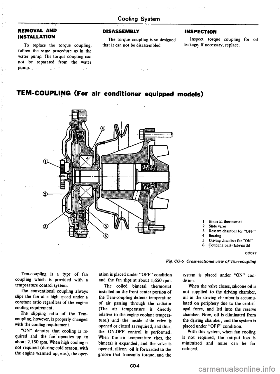
Tem
coupling
is
a
type
of
fan
coupling
which
is
provided
with
a
temperature
control
system
The
conventional
coupling
always
slips
the
fan
at
a
high
speed
under
a
constant
ratio
regardless
of
the
engine
cooling
requirement
The
slipping
ratio
of
the
Tern
coupling
however
is
properly
changed
with
the
cooling
requirement
ON
denotes
that
cooling
is
re
quired
and
the
fan
operates
up
to
about
2
150
rpm
When
high
cooling
is
not
required
during
cold
season
with
the
engine
warmed
up
etc
the
oper
w
6
I
1
Bi
metal
thermostat
2
Slide
valve
3
Reserve
chamber
for
OFF
4
Bearing
5
Driving
chamber
for
ON
6
ouplingpart
labyrinth
coon
Fig
CO
5
CrQM
sectional
view
of
Tem
coupling
ation
is
placed
under
OFF
condition
and
the
fan
slips
at
about
1
650
rpm
The
coiled
bimetal
thermostat
installed
on
the
front
center
portion
of
the
Tem
coupling
detects
temperature
of
air
passing
through
the
radiator
The
air
temperature
is
directly
relative
to
the
engine
coolant
tempera
ture
and
the
inside
slide
valve
is
opened
or
closed
as
required
and
thus
the
ON
OFF
control
is
performed
When
the
air
temperature
rises
the
bimetal
is
expanded
and
the
valve
is
opened
silicon
oil
is
forwarded
to
the
groove
that
transmits
torque
and
the
CO
4
system
is
placed
under
ON
con
dition
When
the
valve
closes
silicone
oil
is
not
supplied
to
the
driving
chamber
oil
in
the
driving
chamber
is
accumu
lated
on
periphery
due
to
the
centrif
ugal
force
and
led
into
the
reserve
chamber
Now
oil
is
eliminated
from
the
driving
chamber
and
the
system
is
placed
under
OFF
condition
With
this
system
when
fan
cooling
is
not
required
the
output
loss
is
minimized
and
noise
can
be
far
reduced
Page 96 of 537
Condition
Loss
of
water
Poor
circulation
Corrosion
Overheating
Overcooling
Cooling
System
TROUBLE
DIAGNOSES
AND
CORRECTIONS
Probable
cause
Damaged
radiator
seams
Leaks
at
heater
connections
or
plugs
Leak
at
water
temperature
gauge
Loose
joints
Damaged
cylinder
head
gasket
Cracked
cylinder
block
Cracked
cylinder
head
Loose
cylinder
head
bolts
Restriction
in
system
Insufficient
coolant
Inoperative
water
pump
Loose
fan
belt
Inoperative
thermostat
Excessive
impurity
in
water
Infrequent
flushing
and
draining
of
system
Inoperative
thermostat
Radiator
fin
choked
with
mud
chaff
etc
Incorrect
ignition
and
valve
timing
Dirty
oil
and
sludge
in
engine
Inoperative
water
pump
Loose
fan
belt
Restricted
radiator
Inaccurate
temperature
gauge
Impurity
in
water
Inoperative
thermostat
Inaccurate
temperature
gauge
CO
7
Corrective
action
Repair
Repair
Tigh
ten
Tighten
Replace
Check
engine
oil
for
contamination
and
refill
as
necessary
Replace
Check
engine
oil
in
crankcase
for
mixing
with
water
by
pulling
oil
level
gauge
Replace
Tighten
Check
hoses
for
crimps
and
clear
the
system
of
rust
and
sludge
by
flushing
radiator
Replenish
Replace
Adjust
Replace
Use
soft
clean
water
Rain
water
is
satis
factory
Cooling
system
should
be
drained
and
flushed
periodically
Permanent
anti
freeze
Ethylene
glycol
base
can
be
used
through
out
the
seasons
of
the
year
and
change
periodically
at
intervals
recommended
Replace
Clean
out
air
passage
thoroughly
by
using
air
pressure
from
engine
side
of
radiator
Adjust
Refill
Replace
Adjust
Flush
radiator
Replace
Use
soft
clean
water
Replace
Replace
Page 139 of 537
Emission
Control
System
EARLY
FUEL
EVAPORATIVE
SYSTEM
E
F
E
DESCRIPTION
spring
and
counterweight
which
are
assembled
on
the
valve
shaft
projecting
to
the
rear
outside
of
the
exhaust
manifold
The
counterweight
is
se
cured
to
the
valve
shaft
with
key
bolt
and
snap
ring
EC
4
A
control
valve
welded
to
the
valve
shaft
is
wtalled
on
the
exhaust
manifold
through
bushing
This
con
trol
valve
is
called
Heat
control
valve
The
heat
control
valve
is
ac
luated
by
the
coil
spring
thermostat
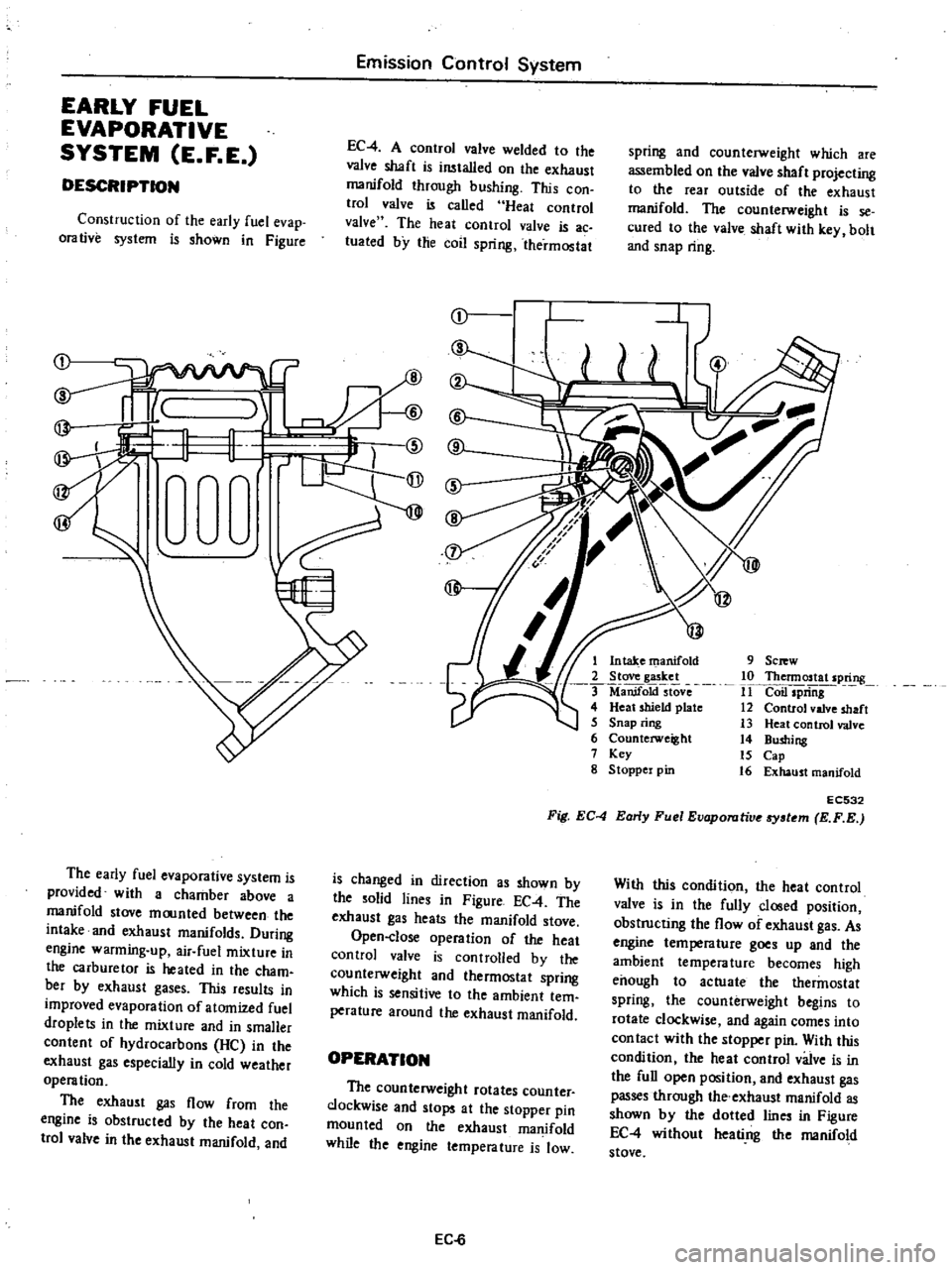
Construction
of
the
early
fuel
evap
orative
system
is
shown
in
Figure
r
I
1
@
rW
9
Sc
w
10
Thennostat
spring
11
Coil
spriiig
12
Control
valve
shaft
13
Heat
control
valve
14
Bushing
15
Cap
16
Exhaust
manifold
1
Intake
manifold
2
Stove
gasket
ManifoktstOve
4
Heat
shield
plate
5
Snap
ring
6
Counterweight
7
Key
g
Stoppel
pin
EC532
Fig
EC
4
Early
Fuel
Evaporutive
tem
E
F
E
The
early
fuel
evaporative
system
is
provided
with
a
chamber
above
a
manifold
stove
moonted
between
the
intake
and
exhaust
manifolds
During
engine
warming
up
air
fuel
mixture
in
the
carburetor
is
heated
in
the
cham
bet
by
exhaust
gases
This
results
in
improved
evaporation
of
atomized
fuel
droplets
in
the
mixture
and
in
smaller
content
of
hydrocarbons
He
in
the
exhaust
gas
especially
in
cold
weather
operation
The
exhaust
gas
flow
from
the
engine
is
obstructed
by
the
heat
con
trol
valve
in
the
exhaust
manifold
and
is
changed
in
direction
as
shown
by
the
solid
lines
in
Figure
EC
4
The
exhaust
gas
heats
the
manifold
stove
Open
close
operation
of
the
heat
control
valve
is
controlled
by
the
counterweight
and
thermostat
spring
which
is
sensitive
to
the
ambient
tem
perature
around
the
exhaust
manifold
With
this
condition
the
heat
control
valve
is
in
the
fully
closed
position
obstructing
the
flow
of
exhaust
gas
As
engine
tempera
lure
goes
up
and
the
ambient
temperature
becomes
high
enough
to
actuate
the
thermostat
spring
the
counterweight
begins
to
rotate
clockwise
and
again
comes
into
con
tact
with
the
stopper
pin
With
this
condition
the
heat
control
valve
is
in
the
full
open
position
and
exhaust
gas
passes
through
the
exhaust
manifold
as
shown
by
the
dotted
lines
in
Figure
EC
4
without
heati
ng
the
manifold
stove
OPERATION
The
counterweight
rotates
counter
clockwise
and
stops
at
the
stopper
pin
mounted
on
the
exhaust
manifold
while
the
engine
temperature
is
low
EC
6
Page 200 of 537
Engine
Electrical
System
SERVICE
DATA
AND
SPECIFICATIONS
D4A4
06
D4A4
07
Type
D4A6
07
D4A6
08
Firing
order
1
3
4
2
13
4
2
Rotating
direction
Counterclockwise
Counterclockwise
Owen
angle
degree
490
to
550
490
to
550
Point
gap
mm
in
0
45
to
0
55
0
45
to
0
55
0
018
to
0
022
0
018
to
0
022
Point
pressure
kg
lb
0
40
to
0
55
0
40
to
0
55
0
88
to
1
21
0
88
to
1
21
Condenser
capacity
JlF
0
20
to
0
24
0
20
to
0
24
Condenser
isolate
resistance
Mrl
5
5
Cap
isolate
resistance
Mrl
50
50
Rotor
head
isolate
resistance
Mrl
50
50
Cap
carbon
point
length
mm
in
10
0
39
10
0
39
For
Canada
DISTRIBUTOR
California
models
CONSTRUCTION
CHECKING
AND
ADJUSTMENT
CAP
AND
ROTOR
HEAD
AIR
GAP
CONSTRUCTION
In
the
conventional
distributor
the
ignition
liming
is
detected
by
the
cam
and
breaker
arm
while
in
this
transis
tor
ignition
unit
it
is
detected
by
the
reluctor
on
the
shaft
and
the
pick
up
coil
provided
in
place
of
the
breaker
The
pick
up
coil
consists
of
a
magnet
coil
etc
The
amount
of
magnetic
flux
passing
through
the
pole
piece
in
the
coil
is
changed
at
the
moment
the
pole
CONTENTS
EE
33
EE
33
EE
33
EE
33
ADVANCE
MECHANISMS
DISASSEMBLY
ASSEMBLY
SERVICE
DATA
AND
SPECIFICATIONS
EE
33
EE
35
EE
35
EE
36
piece
faces
the
protrusion
of
the
re
luctor
and
then
the
electrical
signal
is
genera
ted
in
the
pick
up
coil
This
electric
signal
is
conducted
into
the
transistor
ignition
unit
which
in
turn
breaks
tI
e
primary
coil
current
running
through
the
ignition
coil
and
generates
high
voltage
in
the
secondary
winding
Also
this
transistor
ignition
EE
33
unit
utilizes
this
electric
signal
to
restore
the
primary
coil
to
the
original
state
after
cutting
off
the
primary
current
for
a
fIXed
time
The
centrifugal
and
vacuum
ad
vance
mechanisms
employ
the
con
ventional
mechanical
type
The
con
tactor
is
used
to
eliminate
vacuum
and
centrifugal
advance
hysteresis
I