oil change DATSUN PICK-UP 1977 User Guide
[x] Cancel search | Manufacturer: DATSUN, Model Year: 1977, Model line: PICK-UP, Model: DATSUN PICK-UP 1977Pages: 537, PDF Size: 35.48 MB
Page 229 of 537
Inspection
Note
To
clean
or
wash
all
parts
of
master
cylinder
operating
cylinder
and
piping
clean
brake
fluid
must
be
used
Never
use
minera10ils
llUch
as
gasoline
and
kerosene
It
will
ruin
the
rubber
parts
of
the
hydrau
lic
system
I
Check
cylinder
and
piston
for
uneven
wear
or
damage
and
if
neces
sary
replace
2
If
the
clearance
between
cylinder
and
piston
is
more
than
0
15
mm
0
0059
in
replace
cylinder
3
Renew
piston
cup
when
dis
assembled
It
must
also
be
replaced
when
wear
or
deformation
due
to
fatigue
or
damage
is
found
4
Damaged
dust
cover
oil
reservoir
or
cap
should
be
replaced
Return
spring
and
valve
spring
must
also
be
replaced
when
they
are
broken
or
weak
5
Replace
clutch
hose
and
tube
if
any
abnormal
sign
of
damage
or
de
fro
ti
n
is
found
OPERATING
CYLINDER
Removal
and
installation
Removal
1
Detach
clutch
hose
from
operat
ing
cylinder
2
Remove
two
bolts
securing
op
erating
cylinder
to
clutch
housing
Installation
Install
in
the
reverse
order
of
re
moval
Observe
the
following
instructions
Bleed
air
thoroughly
from
clutch
hydraulic
system
2
Do
not
install
return
spring
or
clutch
will
not
be
disengaged
properly
Tightening
torque
Operating
cylinder
securing
bolt
2
5
to
3
5
kg
m
18
to
25
ft
lb
Bleeder
screw
0
7
to
0
9
kg
m
5
1
to
6
5
ft
Ib
Clutch
hose
connector
1
7
to
2
0
kg
m
12
to
14
ft
b
CLUTCH
Disassembly
and
assembly
Disassembly
1
Remove
push
rod
with
dust
cover
2
Remove
piston
assembly
and
pis
ton
spring
3
Remove
bleeder
screw
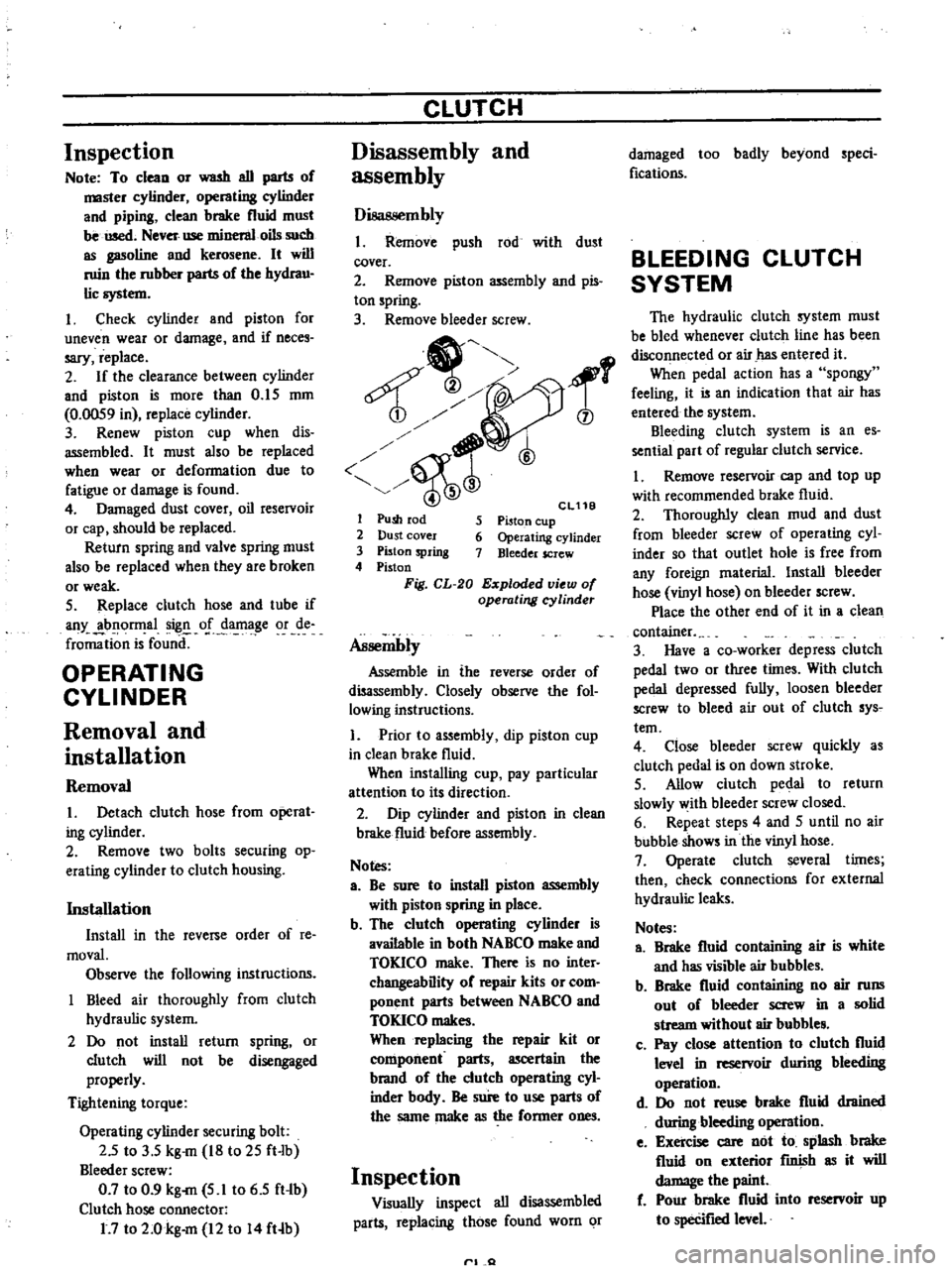
1
6
Cl11B
5
Piston
cup
6
Operating
cylinder
7
Bleeder
screw
1
Push
rod
2
Dust
cover
3
Piston
spring
4
Piston
Fig
CL
20
Exploded
view
of
operating
cyUnder
Assembly
Assemble
in
the
reverse
order
of
disassembly
Closely
observe
the
fol
lowing
instructions
1
Prior
to
assembly
dip
piston
cup
in
clean
brake
fluid
When
installing
cup
pay
particular
attention
to
its
direction
2
Dip
cylinder
and
piston
in
clean
brake
fluid
before
assembly
Notes
a
Be
sure
to
install
piston
assembly
with
piston
spring
in
place
b
The
clutch
operating
cylinder
is
available
in
both
NABCO
make
and
TOKICO
make
There
is
no
inter
changeability
of
repair
kits
or
com
ponent
parts
between
NABCO
and
TOKICO
makes
When
replacing
the
repair
kit
or
component
parts
ascertain
the
brand
of
the
clutch
operating
cyl
inder
bndy
Be
sure
to
use
parts
of
the
same
make
as
the
former
ones
Inspection
Visually
inspect
all
disassembled
parts
replacing
those
found
worn
or
rl
Q
damaged
too
badly
beyond
speci
fications
BLEEDING
CLUTCH
SYSTEM
The
hydraulic
clutch
system
must
be
bled
whenever
clutch
line
has
been
disconnected
or
air
has
entered
it
When
pedal
action
has
a
spongy
feeling
it
is
an
indication
that
air
has
entered
the
system
Bleeding
clutch
system
is
an
es
sential
part
of
regular
clutch
service
I
Remove
reservoir
cap
and
top
up
with
recommended
brake
fluid
2
Thoroughly
clean
mud
and
dust
from
bleeder
screw
of
operating
cyl
inder
so
that
outlet
hole
is
free
from
any
foreign
rnaterial
Install
bleeder
hose
vinyl
hose
on
bleeder
screw
Place
the
other
end
of
it
in
a
clean
container
3
Have
a
co
worker
depress
clutch
pedal
two
or
three
times
With
clu
tch
pedal
depressed
fully
loosen
bleeder
screw
to
bleed
air
out
of
clutch
sys
tern
4
Close
bleeder
screw
quickly
as
clutch
pedal
is
on
down
stroke
5
Allow
clutch
pedal
to
return
slowly
with
bleeder
screw
closed
6
Repeat
steps
4
and
5
until
no
air
bubble
shows
in
the
vinyl
hose
7
Operate
clutch
several
times
then
check
connections
for
external
hydraulic
leaks
Notes
a
Brake
fluid
containing
air
is
white
and
has
visible
air
bubbles
b
Brake
fluid
containing
no
air
runs
out
of
bleeder
screw
in
a
solid
stream
without
air
bubble
c
Pay
close
attention
to
clutch
fluid
level
in
reservoir
during
bleeding
operation
d
Do
not
reuse
brake
fluid
drained
during
bleeding
operation
e
Exercise
care
not
to
splash
brake
fluid
on
exterior
fInish
as
it
will
damage
the
paint
f
Pour
brake
fluid
into
reservoir
up
to
specifIed
level
Page 231 of 537
CLUTCH
TROUBLE
DIAGNOSES
AND
CORRECTIONS
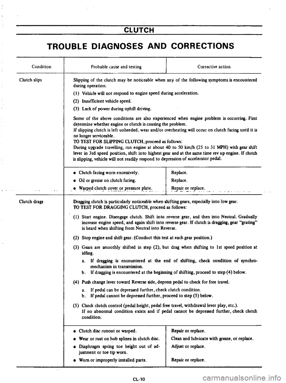
Condition
Probable
cause
and
testing
Clutch
slips
Corrective
action
Slipping
of
the
clutch
may
be
noticeable
when
any
of
the
following
symptoms
is
encountered
during
operation
I
Vehicle
will
not
respond
to
engine
speed
during
acceleration
2
Insufficient
vehicle
speed
3
Lack
of
power
during
uphill
driving
Some
of
the
above
conditions
are
also
experienced
when
engine
problem
is
oc
urring
First
de
tennine
whether
engine
or
clutch
is
causing
the
problem
If
slipping
clutch
is
left
unheeded
wear
and
or
overheating
will
occur
on
clutch
facing
until
it
is
no
longer
serviceable
TO
TEST
FOR
SLIPPING
CLlJfCH
proceed
as
follows
During
upgrade
travelling
run
engine
at
about
40
to
50
km
h
25
to
31
MPH
with
gear
shift
lever
in
3rd
speed
position
shift
into
highest
gear
and
at
the
same
time
rev
up
engine
If
clutch
is
slipping
vehicle
will
not
readily
respond
to
depression
of
accelerator
pedal
Clutch
facing
worn
excessively
Oil
or
grease
on
clutch
facing
W
r
d
clut
h
cov
r
pressure
plat
Replace
Replace
tpa
o
e
lace
Dragging
clutch
is
particularly
noticeable
when
shifting
gears
especially
into
low
gear
TO
TEST
FOR
DRAGGING
CLlJfCH
proceed
as
follows
I
Start
engine
Disengage
clutch
Shift
into
reverse
gear
and
then
into
Neutral
Gradually
increase
engine
speed
and
again
shift
into
reverse
gear
If
clutch
is
dragging
gear
grating
is
heard
when
shifting
from
Neutral
into
Reverse
Clutch
drags
2
Stop
engine
and
shift
gear
Conduct
this
test
at
each
gear
position
3
Gears
are
smoothly
shifted
in
step
2
but
drag
when
shifting
to
1st
speed
position
at
idling
a
If
dragging
is
encountered
at
the
end
of
shifting
check
condition
of
synchro
mechanism
in
transmission
b
If
dragging
is
encountered
at
the
beginning
of
shifting
proceed
to
step
4
below
4
Push
change
lever
toward
Reverse
side
depress
pedal
to
check
for
free
travel
a
If
pedal
can
be
depressed
further
check
clutch
condition
b
If
pedal
cannot
be
depressed
further
proceed
to
step
5
below
5
Check
clutch
control
pedal
height
pedal
free
travel
withdrawal
lever
play
etc
If
no
abnonnal
condition
exists
and
if
pedal
cannot
be
depressed
further
check
clutch
condition
Clutch
disc
runout
or
warped
Wear
or
rust
on
hub
splines
in
clutch
disc
Diaphragm
spring
toe
height
out
of
ad
justment
or
toe
tip
worn
Worn
or
improperly
installed
parts
CL10
Repair
or
replace
Clean
and
lubricate
with
grease
or
replace
Adjust
or
replace
Repair
or
replace
Page 247 of 537
Note
Prior
to
assembling
reverse
fork
rod
instaU
two
2
interlock
balls
into
adapter
piate
as
shown
in
Figure
MT
I6
6
Install
check
ball
and
check
ball
spring
Apply
sealant
to
check
ball
plug
and
install
it
in
place
Align
notch
in
reverse
fork
rod
with
check
ball
See
Figure
MT
52
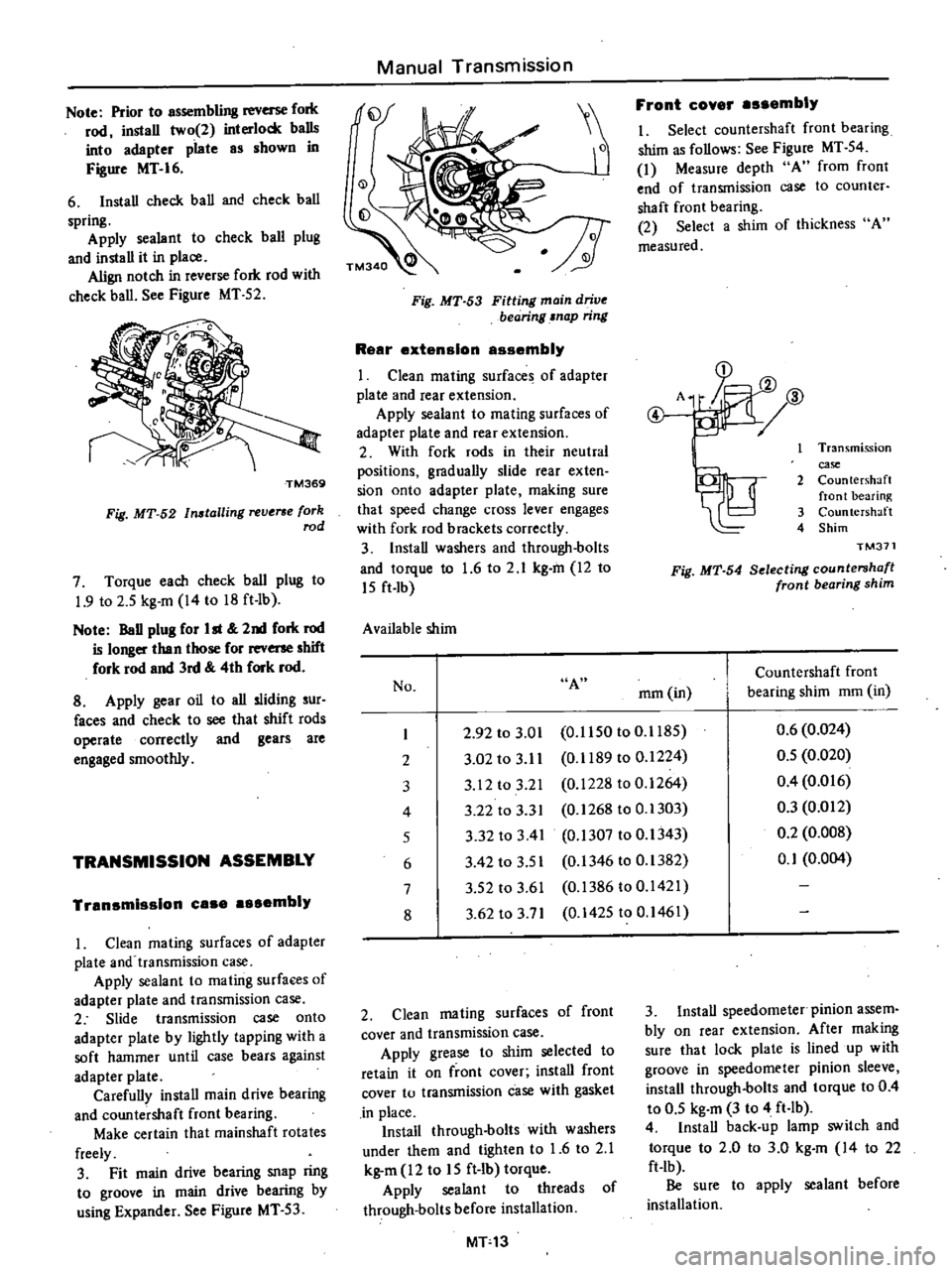
TM369
Fig
MT
52
Installing
reverse
fork
rod
7
Torque
each
check
ball
plug
to
1
9
to
2
5
kg
m
14
to
18
ft
Ib
Note
BaD
plug
for
ht
2nd
fork
rod
is
longer
than
those
for
rev
shift
fork
rod
and
3rd
4th
fork
rod
8
Apply
gear
oil
to
all
sliding
sur
faces
and
check
to
see
that
shift
rods
operate
correctly
and
gears
are
engaged
smoothly
TRANSMISSION
ASSEMBLY
Tran
mis
lon
ea
mbly
1
Clean
mating
surfaces
of
adapter
plate
and
transmission
case
Apply
sealant
to
mating
surfaces
of
adapter
plate
and
transmission
case
2
Slide
transmission
case
onto
adapter
plate
by
lightly
tapping
with
a
soft
hammer
until
case
bears
against
adapter
plate
Carefully
install
main
drive
bearing
and
countershaft
front
bearing
Make
certain
that
mainshaft
rotates
freely
3
Fit
main
drive
bearing
snap
ring
to
groove
in
main
drive
bearing
by
using
Expander
See
Figure
MT
53
Manual
Transmission
Fig
MT
53
Fitting
main
drive
bearing
snap
ring
R
ar
xt
nslon
ass
mbly
I
Clean
mating
surfaces
of
adapter
plate
and
fear
extension
Apply
sealant
to
mating
surfaces
of
adapter
plate
and
rear
extension
2
With
fork
rods
in
their
neutral
positions
graduaUy
slide
rear
exten
sion
onto
adapter
plate
making
sure
that
speed
change
cross
lever
engages
with
fork
rod
brackets
correctly
3
Install
washers
and
through
bolts
and
torque
to
1
6
to
2
1
kg
m
12
to
15
ft
lb
Available
shim
Front
eov
r
s
mbly
I
Select
countershaft
front
bearing
shim
as
follows
See
Figure
MT
54
1
Measure
depth
A
from
front
end
of
transmission
case
to
counter
shaft
front
bearing
2
Select
a
shim
of
thickness
A
measured
D
A
JJ
ID
@
2J1
I
Transmission
case
2
Countershaft
front
bearing
3
Countershaft
4
Shim
TM371
Fig
MT
54
Selecting
countershafl
front
bearing
shim
No
A
Countershaft
front
rnm
in
bearing
shim
mm
in
I
2
92
to
3
01
0
1150
to
0
1185
0
6
0
024
2
3
02
to
3
11
0
1189
to
0
1224
0
5
0
020
3
3
12
to
3
21
0
1228
to
0
1264
0
4
0
016
4
3
22
to
3
3
I
0
1268
to
0
1303
0
3
0
012
5
3
32
to
3
41
0
1307
to
0
1343
0
2
0
008
6
3
42
to
3
5
I
0
1346
to
0
1382
0
1
0
004
7
3
52
to
3
61
0
1386
to
0
1421
8
3
62
to
3
71
0
1425
to
0
1461
2
Clean
mating
surfaces
of
front
cover
and
transmission
case
Apply
grease
to
shim
selected
to
retain
it
on
front
cover
install
front
cover
to
transmission
case
with
gasket
in
place
Install
through
bolts
with
washers
under
them
and
tighten
to
1
6
to
2
1
kg
m
12
to
15
ft
lb
torque
Apply
sealant
to
threads
of
through
bolts
before
installation
MT13
3
Install
speedometer
pinion
assem
bly
on
rear
extension
After
making
Sure
that
lock
plate
is
lined
up
with
groove
in
speedometer
pinion
sleeve
install
through
bolts
and
torque
to
0
4
to
0
5
kg
m
3
to
4
ft
lb
4
Install
back
up
lamp
switch
and
torque
to
2
0
to
3
0
kg
m
14
to
22
ft
lb
Be
sure
to
apply
sealant
before
installation
Page 265 of 537
plate
The
parking
rod
pin
operates
the
rod
at
p
range
and
operates
the
mechanical
lock
system
The
above
described
manual
shaft
is
further
equipped
with
an
inhibitor
switch
A
rotor
inside
the
inhibitor
switch
rotates
in
response
to
each
range
When
tne
range
is
selected
at
p
or
N
the
rotor
closes
the
starter
magnet
circuit
so
that
the
engine
can
be
started
When
the
range
is
selected
at
R
the
rolor
closes
the
back
up
lamp
circuit
and
the
back
up
lamp
lights
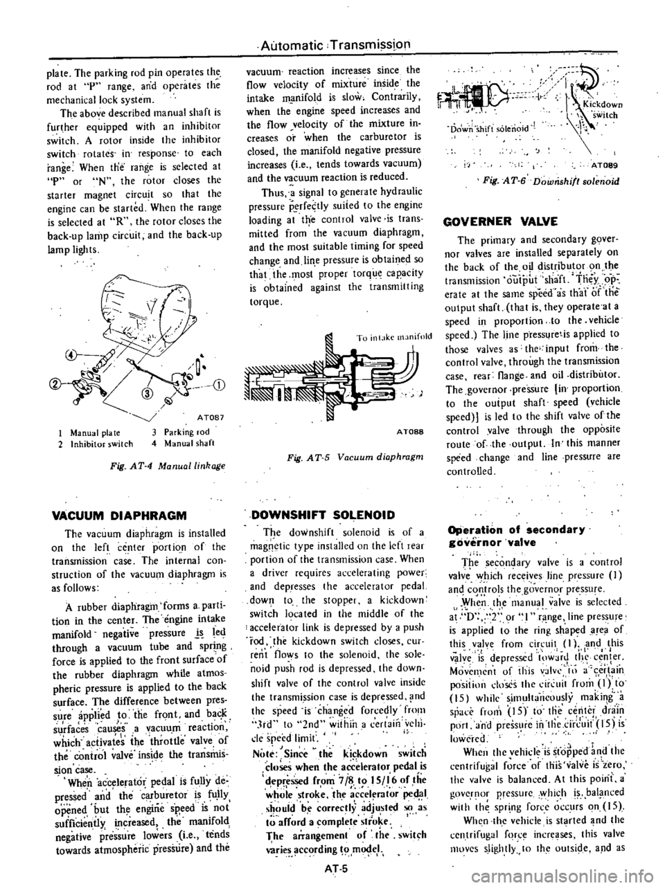
CD
1
Manual
pia
te
2
Inhibitor
switch
ATOB7
Parking
rod
Manual
shaft
Fig
AT
4
Manual
linkage
VACUUM
DIAPHRAGM
The
vacuum
diaphragm
is
installed
on
the
left
center
portio
n
of
the
transmission
case
The
internal
con
struction
of
the
vacuum
diaphragm
is
as
follows
A
rubber
diaphragm
forms
a
parti
tion
in
the
center
The
engine
intake
manifold
negative
pressure
l
led
through
a
vacuum
tube
and
spring
force
is
applied
to
the
front
surfaceof
the
rubber
diaphragm
while
atmos
pheric
pressure
is
applied
to
the
back
surface
The
difference
between
pres
sure
applied
to
the
front
and
ba
K
I
surfaces
causes
a
vacuum
reactIOn
which
activates
the
throttle
valve
of
the
control
valve
inside
the
transrhis
sion
case
Wheri
accelerator
pedal
is
fully
de
pressed
and
the
buretor
is
fU
IIy
opened
but
th
engirie
sp
eed
is
not
suificientl
increased
the
manifold
negative
plre
sure
lowers
Le
tends
towards
atmospheric
pressure
and
the
Automatic
Transmission
vacuum
reaction
increases
since
the
flow
velocity
of
mixture
inside
the
intake
m
mifold
is
slow
Contrarily
when
the
engine
speed
increases
and
the
flow
velocity
of
the
mixture
in
creases
or
when
the
carburetor
is
closed
the
manifold
negative
pressure
increases
Le
tends
towards
vacuum
and
the
vacuum
reaction
is
reduced
Thus
a
signal
to
genera
Ie
hydraulic
pressure
P
rfe
tly
suited
to
the
engine
loading
at
trye
control
valve
is
trans
mitted
from
the
vacuum
diaphragm
and
the
most
suitable
timing
for
speed
change
and
lin
e
pressure
is
obtaine
so
that
the
most
proper
torque
capacity
is
obtained
against
the
transmitting
torque
To
inl
lkc
manifold
AT088
Fig
AT
5
Vacuum
diaphragm
DOWNSHIFT
SOLENOID
T
e
downshift
solenoid
is
of
a
magnetic
type
installed
on
the
left
re
r
portion
of
the
transmission
case
When
a
driver
requires
accelerating
power
and
dePresses
the
accelerator
pedal
down
to
the
stopper
a
kickdown
switch
19ca
ted
in
the
middle
of
the
accelerator
link
is
depressed
by
a
push
rod
he
kickdown
switch
doses
cur
rent
flows
to
the
solenoid
the
sole
noid
push
rod
is
depressed
the
down
shift
valve
of
the
control
valvc
insidc
the
transmi
ssion
case
is
depressed
nd
the
speed
is
changed
forcedly
fmm
3rd
to
2nd
within
a
cerlaill
vehi
cle
speed
limit
Note
Since
theki
kdown
switch
closes
when
the
accelerator
pedal
is
d
epr
ssed
from
7
i
t
I
S
I
6
of
tiie
whole
stroke
the
a
ccel
rator
ped
1
should
be
correctly
adjusted
so
as
arf
rd
a
omplete
stro
e
I
The
arrangement
of
the
swit
h
wries
ccording
m
eI
AT
S
c
C
r
11
I
Kickdown
h
switch
Dowri
shift
solenoid
AT089
Fig
AT
6
Downshifl80lenoid
GOVERNER
VALVE
The
primary
and
secondary
gover
nor
valves
are
installed
separately
on
the
back
of
the
oil
distributor
on
the
transmission
outp
t
sha
ft
tn
y
op
erate
al
the
same
speed
as
th
ar
iJf
tile
output
shaft
thai
is
they
operate
at
a
speed
in
proportion
10
the
vehicle
speed
The
line
press
retis
applied
to
those
valves
s
the
input
from
the
control
valve
through
the
transmission
case
rear
flange
and
oil
distributor
The
governor
pressure
in
proportion
to
the
ouiput
shaft
speed
vehicle
speed
is
led
to
the
shift
valve
ofthe
control
valve
through
the
opposite
route
of
the
output
In
this
manner
speed
change
and
line
pressure
are
controlled
Operation
of
secondary
governor
valve
T
e
secon
ary
valve
is
a
contro
valve
Y
hich
receives
line
pressure
an
cqQ
rols
the
governor
pressu
e
When
the
manual
valve
is
selected
at
D
2
or
l
range
line
pressure
is
applied
t
the
ri
g
sh
aped
area
of
this
valve
from
circuit
I
l
and
this
I
v
Jy
is
depressed
lOW
jr
tI
c
fer
Movemcnt
of
this
valvl
III
a
cr
in
positillll
doses
the
dr
uit
from
Olto
15
while
simultaneously
making
a
sr
rronl
IS
to
Iii
center
d
niin
port
and
press
re
in
tllc
ci
rJ
it
l5j
is
lowered
When
thc
vehicle
is
stopped
1
d
the
cenlrifugal
force
of
this
valve
is
zero
the
v
lve
is
balanced
At
this
poini
a
govcr
lOr
pressurc
y
hich
bal
i1
nced
with
th
spr
ng
force
occurs
on
IS
Wh
n
thc
vehicle
is
st
rted
nd
the
centrifugal
fqr
incre
ses
this
valve
movcs
slightly
10
Ihc
oUlSide
and
as
Page 266 of 537
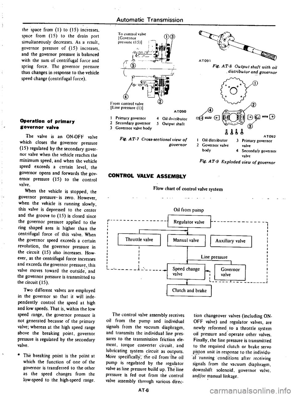
the
space
from
I
to
IS
increases
space
from
15
to
the
drain
port
simultaneously
decreases
As
a
resull
governor
pressure
of
15
increases
and
the
governor
pressure
is
balanced
with
the
sum
of
centrifugal
force
and
spring
force
The
governor
pressure
thus
changes
in
response
to
the
vehicle
speed
change
centrifugal
force
Operation
of
prlmar
governor
valve
The
valve
is
an
ON
OFF
valve
which
closes
the
governor
pressure
IS
regulated
by
the
secondary
gover
nor
valve
when
the
vehicle
reaches
the
minimum
speed
and
when
the
vehicle
speed
exceeds
a
certain
level
the
governor
opens
and
forwards
the
gov
ernor
pressure
15
to
the
control
valve
When
the
vehicle
is
stopped
the
governor
pressure
is
zero
However
when
the
vehicle
is
running
slowly
this
valve
is
depressed
to
Ihe
center
and
the
groove
to
15
is
closed
since
the
governor
pressure
applied
to
the
ring
shaped
area
is
higher
than
the
centrifugal
force
of
this
valve
When
the
governor
speed
exceeds
a
certain
revolution
the
governor
pressure
in
the
circuit
15
also
increases
How
ever
as
the
centrifugal
force
increases
and
exceeds
the
governor
pressure
this
valve
moves
toward
the
outside
and
the
governor
pressure
is
transmitted
to
the
circuil
5
Two
different
valves
are
employed
in
the
governor
so
that
it
will
inde
pendently
control
the
speed
at
high
and
low
speeds
That
is
within
the
low
speed
range
the
governor
pressure
is
not
generated
because
of
the
primary
valve
whereas
at
the
high
speed
range
above
the
breaking
point
governor
pressure
is
regulated
by
the
secondary
valve
The
breaking
point
is
the
point
at
which
the
function
of
one
of
the
governor
is
transferred
to
the
other
as
the
speed
changes
from
the
low
speed
to
the
high
speed
range
Automatic
Transmission
To
onlml
valve
l
Governor
pre
S1I
1I5
j
I
Q
J
J
f
1
1
CID
l
l
m
Line
pressure
t
D@
I
Primary
governor
2
Secondary
governor
3
Governor
valve
body
AT090
4
Oil
di
lributor
5
Output
sh
lft
Fig
AT
7
Cr05s
sectionallliew
of
governor
CONTROL
VALVE
ASSEMBLY
Ai09
Fig
AT
S
Output
shaft
with
oil
distributor
and
overnor
r
@
@
0
aBUlllI8
iUQlli
V
JlAU
I
Oil
distributor
2
Governor
nlve
body
A
T092
3
Primary
governor
valve
4
Secondary
governol
valve
Fig
A
T
9
Exploded
view
of
governor
Flow
cbar
of
control
valve
system
Oil
from
pump
Regulator
valve
1
I
i
j
Throttle
valve
I
I
l
Manual
valve
I
I
I
I
I
I
I
L
n
L
j
Speed
change
valve
I
I
t
t
I
I
I
I
I
I
Governor
I
I
valve
I
I
I
L
L
1
II
Auxiliary
valve
Line
pressure
j
Clutch
and
brake
The
control
valve
assembly
receives
oil
from
the
pump
and
individual
signals
from
the
vacuum
diaphragm
and
transmits
the
individual
line
pres
sures
to
the
transmission
friction
ele
ment
torque
converter
circuit
and
lubricating
system
circuit
as
outputs
More
specifically
the
oil
from
the
oil
pump
is
regulated
by
the
regulator
valve
as
line
pressure
build
up
the
line
pressure
is
fed
out
from
the
control
valve
assembly
through
various
direc
AT
6
tion
changeover
valves
including
ON
OFF
valve
and
regulator
valves
are
newly
reformed
to
a
throllle
system
oil
pressure
and
operate
other
valves
Finally
the
line
pressure
is
transmilled
to
the
required
dutch
or
brake
servo
pisJon
unit
in
response
to
the
individu
af
running
conditions
after
re
ejving
signals
from
the
va
uum
diaphragm
downshift
solenoid
governor
V
dlvc
and
or
manual
linkage
Page 269 of 537

3
Jit
f
ng
valve
24
1
3
L
l
r
I
Js
I
i
ilr
t
pressure
6
when
shif
ing
from
3rd
to
2nd
at
D
range
Thus
the
throttle
of
line
pressure
6
reduces
the
shock
generated
fro
shifting
A
plug
in
the
SSV
left
end
readjust
the
throttle
piessu
e
I
6
which
varies
depending
on
the
engine
throttle
con
dition
to
a
throttle
pressure
19
suiled
to
the
sp
ed
change
control
Moreover
the
plug
is
a
valve
which
applies
line
P
esspre
13
in
lieu
of
the
throttle
pressure
to
the
SSV
and
the
FSV
when
kickdowri
is
performed
When
the
throttle
pressure
16
is
applied
to
the
left
side
of
this
plug
and
the
plug
is
epressed
toward
the
right
a
slight
space
is
formed
from
the
throttle
pressure
6
10
19
A
throt
tIepressu
19
w
1iFh
is
lower
by
the
pressure
loss
equivalent
to
this
space
is
rH
1
Pressure
Odifier
valve
PMV
I
Compared
to
the
operating
pressure
required
in
starting
th
vehicle
the
ppwer
trimsinitting
capacity
of
the
clutch
that
is
required
operating
pres
sure
may
be
lower
when
the
vehicle
is
once
started
When
the
line
pressure
is
retained
at
a
high
level
up
to
a
high
vehicle
speed
shock
gerieraled
from
the
shirring
increases
arid
the
oil
pump
loss
also
jncrdases
In
order
to
prevent
his
the
t
lrott
le
pressure
must
be
l
hanged
over
with
the
operation
of
the
governor
pressure
15
to
reduce
Ihe
line
pressure
The
PMV
is
used
for
this
purposc
Automatic
Transmission
generated
the
piessure
loss
is
adde
d
to
the
spring
force
and
the
plug
is
lhus
forced
back
from
the
right
to
the
left
When
this
pressure
19
increases
ex
cessively
the
plug
is
further
depressed
toward
the
left
space
from
the
lhrot
tle
pressure
19
to
the
drain
circuit
13
increases
and
the
throttle
press
ure
19
decreases
Thus
the
plug
is
balanced
imd
the
throttle
pressure
19
is
reduced
to
Ii
certain
value
against
the
throttle
pressure
6
Wheri
performing
kickdowri
the
SDV
moves
a
high
line
pressure
is
led
to
the
circuit
19
from
the
line
pressure
circuit
13
which
had
been
drained
the
plug
is
forced
toward
the
left
and
circuit
19
becomes
equal
to
the
line
pressure
13
I
W
15
I
A
TOgS
Fig
iT
13
2nd
3rd
shift
vallJe
I
When
the
governor
pressuie
IS
which
is
applied
to
the
right
side
of
the
PMV
is
low
the
valve
is
forced
toward
the
right
by
the
throttle
ines
sure
16
applied
to
the
area
differ
ence
of
the
value
and
the
spring
foice
and
t
he
circuit
from
circuit
16
to
circuit
18
is
closed
However
when
vehicle
speed
increases
andl
the
gaver
nor
pressure
15
exceeds
a
certain
level
the
governor
pressure
toward
the
left
which
is
applied
to
the
right
side
exceeds
the
spring
force
and
the
throt
tle
pressure
16
toward
thc
right
the
valve
is
depressed
loward
the
lefi
and
the
throttle
pressure
is
led
from
circuit
AT
9
16
to
circuit
18
This
throttle
pressure
18
is
applied
to
the
top
of
the
PRV
and
the
force
of
the
line
pressure
source
7
is
reduced
Contra
rily
when
the
vehicle
speed
decreases
arid
the
governor
ipressure
15
de
creases
the
force
toward
the
fight
exceeds
ithe
governor
pressure
the
valve
is
forced
back
toward
the
right
and
the
throttle
pressure
18
is
drained
to
the
spring
unit
This
valve
is
sWitched
when
the
throttle
pressure
and
the
governor
pressure
are
high
or
when
tIiey
are
both
Tow
i
i
I
11
18
16
n
r
I
I
15
AT099
Fig
AT
14
Pre
ure
modifier
valve
Vacuum
thro
le
valve
VTV
The
vacuum
t
rottle
valve
is
a
regula
tor
valve
whiCh
uses
the
line
pressure
7
for
the
pressure
source
and
regulates
the
throttle
pressure
16
I
which
is
proportioned
t
the
force
of
the
vacuum
diaphragm
The
vacuum
dia
phragm
yories
depending
on
the
engine
throt
le
condition
negative
pressure
in
the
inta
e
line
When
the
line
pressure
7
is
ap
plied
to
the
bottom
through
the
valve
hole
and
the
v
a
ve
is
forced
upward
space
from
the
line
pressure
7
to
the
throttle
pressure
16
is
dosed
and
the
space
from
the
Ihrottle
pressure
16
to
the
drain
circuit
17
is
about
to
open
In
this
operation
the
throttle
pressure
16
becomes
lower
than
the
linep
s
ureY
btthe
p
e
sur
9
iv
alenl
of
the
loss
of
space
and
Ihe
force
depressing
tlie
rod
if
the
vaeuum
diaphragm
is
balanced
wit
Ii
thethrot
tie
pressure
16
a
pplied
upward
tOlthe
bottom
When
the
erigine
torque
is
high
Ihe
negative
pressure
in
the
intake
iirie
rises
tending
ioward
atmospheric
pressure
and
the
force
of
the
rod
to
depress
the
valve
increases
As
a
result
the
valve
is
depressed
downward
the
Page 312 of 537
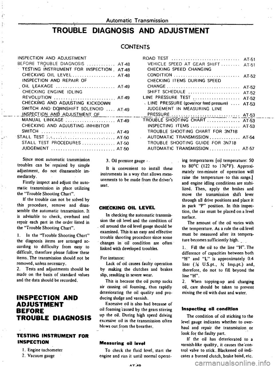
Automatic
Transmission
TROUBLE
DIAGNOSIS
AND
ADJUSTMENT
INSPECTION
AND
ADJUSTMENT
BEFORE
TRQUBLE
DIAGNOSIS
TESTING
INSTRUMENT
FOR
INSPECTION
CHECKING
OIL
LEVEL
INSPECTION
AND
REPAIR
OF
OIL
EAKAGE
CHECKING
ENGINE
IDLING
REVOLUTION
CHECKING
AND
ADJUSTING
KICKDOWN
SWITCH
AND
DqWNSHIFT
SOLENOID
N
J
J
CII
Q
t
L
8li
p
JYSTMs
T
OF
MANUAL
LINKAGE
CHECKING
AND
ADJUSTING
INHIBITOR
SWITCH
STALL
TEST
STALL
TEST
PROCEDURES
JUDGEMENT
Since
most
automatic
transmission
troubles
can
be
repaired
by
simple
adjustment
do
not
disassemble
im
mediately
Firstly
inspect
and
adjust
the
auto
matic
transmission
in
place
utilizing
the
Trouble
Shooting
Chart
If
the
trouble
can
not
be
solved
by
this
procedure
remove
and
disas
semble
the
automatic
transmission
It
is
advisable
to
check
overhaul
and
repair
each
part
in
the
order
listed
in
the
Trouble
Shooting
Chart
I
In
the
Trouble
Shooting
Chart
the
diagnosis
items
are
arranged
ac
cording
to
difficulty
from
easy
to
difficult
therefore
please
follow
these
items
The
transmission
should
not
be
removed
unless
necessary
2
Tests
and
adjustments
should
be
made
on
the
basis
of
standard
values
and
the
data
should
be
recorded
INSPECTION
AND
ADJUSTMENT
BEFORE
TROUBLE
DIAGNOSIS
TESTING
INSTRUMENT
FOR
INSPECTION
I
Engine
tachometer
2
Vacuum
gauge
ROAD
TEST
VEHICLE
SPEED
AT
GEAR
SHIFT
CHECKING
SPEED
CHANGING
CONDITION
CHECKING
ITEMS
DURING
SPEED
CHANGE
SHIFT
SCHEDULE
LINE
PRESSURE
TEST
LINE
PRESSURE
governor
feed
pressure
JUDGEMENT
IN
MEASURING
LINE
PRESSURE
At
49
TR6
uBLE
SHOOTINC
CHART
INSPECTING
ITEMS
TROUBLE
SHOOTING
CHART
FOR
3N71B
AUTOMATIC
TRANSMISSION
TROUBLE
SHOOTING
GUIDE
FOR
3N71B
AUTOMATIC
TRANSMISSION
CONTENTS
AT
4B
AT
48
AT
4B
AT
49
AT
49
AT
49
AT
49
AT
50
AT
50
AT
50
3
Oil
pressure
gauge
It
is
convenient
to
install
these
instruments
in
a
way
that
allows
meas
urements
to
be
made
from
the
driver
s
seat
CHECKING
OIL
LEVEL
In
checking
the
automatic
transmis
sion
the
o
illevel
and
the
condition
of
oil
around
the
oil
level
gauge
should
be
examined
This
is
an
easy
and
effective
trouble
shooting
procedure
since
some
changes
in
oil
condition
are
often
linked
with
developed
troubles
For
instance
Lack
of
oil
causes
faulty
operation
by
making
the
clutches
and
brakes
slip
resulting
in
severe
wear
This
is
because
the
oil
pump
sucks
air
causing
oil
foaming
thus
rapidly
deteriorating
the
oil
quality
and
pro
ducing
sludge
and
varnish
Excessive
oil
is
also
bad
because
of
oil
foaming
caused
by
the
gears
stirring
up
the
oil
During
high
speed
driving
excessive
oil
in
the
transmission
often
blows
out
from
the
breather
Measuring
011
level
To
check
the
fluid
level
start
the
engine
and
run
it
until
normal
operat
T
AO
AT
51
AT
51
AT
52
AT
52
AT
52
AT
52
AT
53
AT
3
AT
53
AT
53
AT
54
AT
57
ing
temperatures
o
temperature
SO
to
800C
122
to
l760F
Approxi
mately
ten
minute
of
operation
will
raise
the
temperature
to
this
range
and
engine
idling
conditions
are
stabi
lized
Then
apply
the
brakes
and
move
the
transmission
shift
lever
through
all
drive
positions
and
place
it
in
park
P
position
In
this
inspec
tion
the
car
must
be
placed
on
a
level
surface
The
amount
of
the
oil
varies
with
the
temperature
As
a
rule
the
oil
level
must
be
measured
after
its
temper
ture
becomes
sufficiently
high
1
Fill
the
oil
to
the
line
H
The
difference
of
capacities
between
both
H
and
L
is
approximately
0
4
liter
Ji
V
S
p
Y
Imp
pl
and
therefore
do
not
to
fill
beyond
the
line
H
2
When
topping
up
and
changing
oil
care
should
be
taken
to
prevent
mixing
the
oil
with
dust
and
water
InspectIng
011
condition
The
condition
of
oil
sticking
to
the
level
gauge
indicates
whether
to
over
haul
and
repair
the
transmission
or
look
for
the
faulty
part
If
the
oil
has
deteriorated
to
a
varnish
ike
quality
it
causes
the
con
trol
valve
to
stick
Blackened
oil
indi
cates
a
burned
clutch
brake
band
etc
Page 316 of 537

CHECKING
SPEED
CHANGING
CONDITION
The
driver
s
feeling
during
gear
changes
should
also
be
checkedatten
tively
I
A
sharp
shock
or
unSffioothness
is
felt
during
a
gear
change
2
A
gear
change
is
made
with
a
long
and
dragging
feeling
These
indicate
that
the
tIuottle
pressure
is
too
low
or
some
valve
connected
to
the
throttle
is
faulty
h
k
100
1
1
2
I
2
J
I
1
2
I
I
I
2
3
oo
I
c
I
E
I
I
300
I
Z
5
L
mmHg
t
1
400
I
I
1
Output
shaft
speed
rpm
20
30
40
50
60
70
80
90100
00
io
3
0
40
0
60
Vehicle
speed
R
4
315
r
0
321
6
00
14
ATll0
Fig
AT
111
Shift
IChedule
Automatic
Transmission
SHI
SCHEDULE
500
CHECKING
ITEMS
DURING
km
hO
1O
SPEED
CHANGE
I
In
D
range
gear
changes
DI
D2
D3
are
effected
In
R
range
the
speed
does
not
increase
2
The
kickdown
operates
properly
3
By
moving
the
lever
from
D
to
I
gear
changes
D
2
1
2
1
are
effected
In
the
ranges
12
and
I
the
engine
braking
works
prop
erly
4
In
I
the
speed
does
not
in
crease
5
Should
be
quickly
fixed
at
2
range
6
In
P
vehicle
can
he
parked
properly
If
any
malfunction
occurs
in
second
gear
during
the
road
test
that
is
if
vehicle
shakes
drags
or
slings
while
shifting
up
from
D
directly
to
D
or
in
shifting
up
from
D
to
D2
the
brake
band
should
be
ad
justed
If
these
troubles
remain
after
the
brake
band
is
adjusted
check
the
servo
piston
seal
for
oil
leakage
MPH
Ii
io
LINE
PRESSURE
TEST
When
any
slipping
occurs
in
clutch
or
brake
or
the
feeling
during
a
speed
change
is
not
correct
the
line
pressure
must
be
checked
Measuring
line
pressure
is
done
by
a
pressure
gauge
attached
to
two
pres
sure
measuring
holes
after
removing
blind
plugs
located
at
transmission
case
See
Figure
AT
112
The
line
pressure
measurement
is
begun
at
idling
and
taken
step
by
step
by
enlarging
the
throttle
opening
I
A
sharp
shock
in
up
shifting
or
too
high
changing
speeds
are
caused
mostly
by
too
high
throttle
pressure
2
Slipping
or
incapability
of
opera
tion
is
mostly
due
to
oil
pressure
leakage
within
the
gear
trains
or
spool
valve
AT
S2
3
3SA
000
t
I
1
I
c
l
1
c
7
D
jf
o
CV
ATl13
1
Lige
pressure
2
Governor
feed
3
SerVo
release
pressure
Fig
AT
112
MeCJ
uring
line
preuure
Page 320 of 537
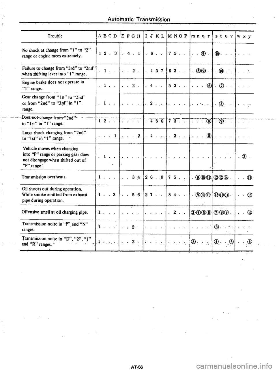
Trouble
No
shock
at
change
from
I
to
2
range
or
engine
races
extremely
Failure
to
change
from
3rd
to
2nd
when
shifting
lever
into
I
range
Engine
brake
does
not
upcrate
in
1
range
Gear
change
frum
I
sr
lu
2nd
or
from
2nd
to
3rd
in
I
range
Does
not
change
f
rom
2nd
to
1st
in
range
Large
shock
changing
from
2nd
to
1st
in
range
Vehicle
moves
when
changing
into
P
range
or
parking
gear
does
not
disengage
when
shifted
out
of
P
range
Transmissic
m
overheats
Oil
shoots
out
during
operation
White
smoke
emitted
from
exhaust
pipe
during
operation
Offensive
smell
at
oil
charging
pipe
Transmission
noise
in
p
and
N
ranges
Transmission
noise
in
D
2
I
and
R
ranges
Automatic
Transmission
ABeD
E
F
G
H
I
J
K
L
1M
NO
P
1m
n
q
r
s
t
u
v
Iw
x
y
6
7
5
@
@
I
I
2
3
4
I
I
2
1
57
6
3
@@
@
I
2
4
5
3
@
f
1
2
@
1
2
4567
3
@
2
1
3
@
2
4
I
2
I
3
4
2
6
8
7
5
@@@
Q
@@
@
I
3
5
6
2
7
8
4
@@@
Q
@@
@
1
2
O
G
@@
f
@@
@
1
2
10
I
I
2
0
G
@
@
AT
56
Page 331 of 537
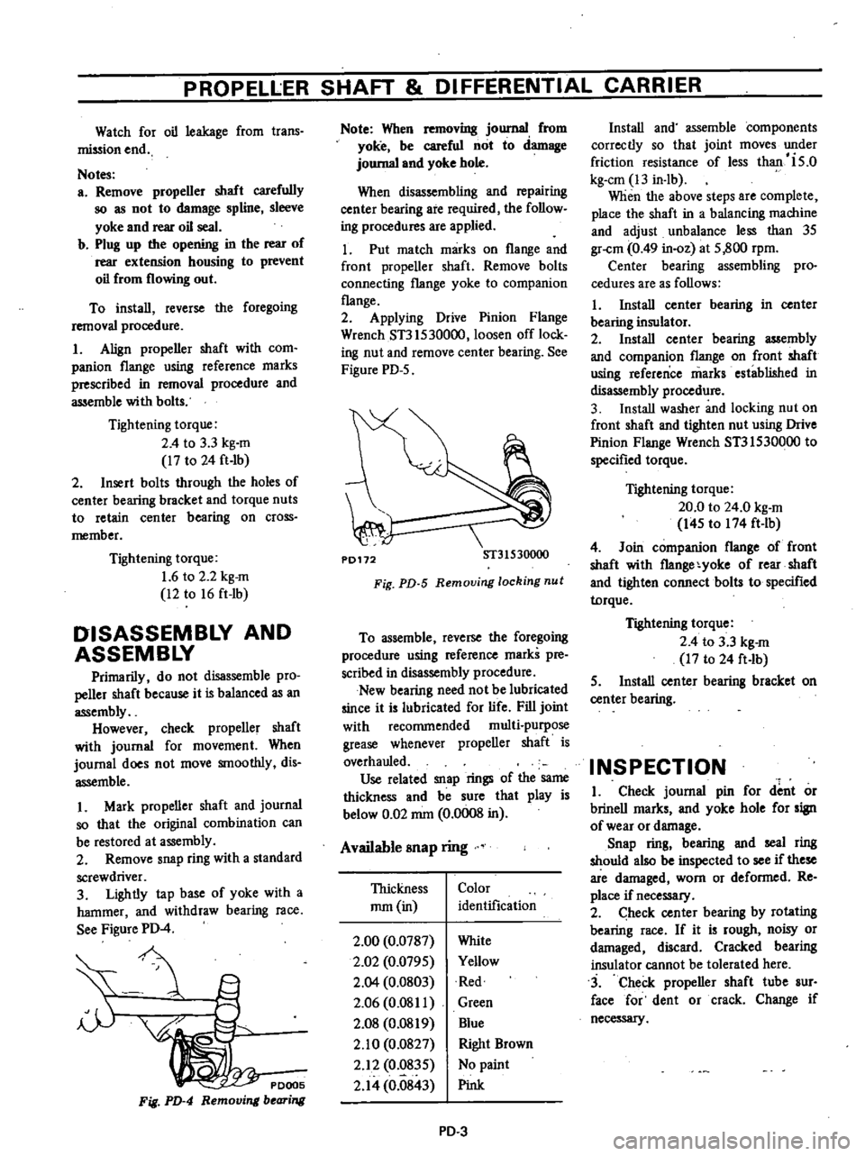
PROPELLER
SHAFT
DIFFERENTIAL
CARRIER
Watch
for
oil
leakage
from
trans
mission
end
Notes
a
Remove
propeller
shaft
carefully
so
as
not
to
damage
spline
sleeve
yoke
and
rear
oil
seal
b
Plug
up
the
opening
in
the
rear
of
rear
extension
housing
to
prevent
oil
from
flowing
out
To
install
reverse
the
foregoing
removal
procedure
1
Align
propeller
shaft
with
com
panion
flange
using
reference
marks
prescribed
in
removal
procedure
and
assemble
with
bolts
Tightening
torque
2
4
to
3
3
kg
m
17
to
24
ft
Ib
2
Insert
bolts
through
the
holes
of
center
beariug
bracket
and
torque
nuts
to
retain
center
bearing
on
cross
member
Tightening
torque
1
6
to
2
2
kg
m
12
to
16
ft
Ib
DISASSEMBLY
AND
ASSEMBLY
Primarily
do
not
disassemble
pro
peller
shaft
because
it
is
balanced
as
an
assembly
However
check
propeller
shaft
with
journal
for
movement
When
journal
does
not
move
smoothly
dis
assemble
1
Mark
propeller
shaft
and
journal
so
that
the
original
combination
can
be
restored
at
assembly
2
Remove
snap
ring
with
a
standard
screwdriver
3
Lightly
tap
base
of
yoke
with
a
hammer
and
withdraw
bearing
race
See
Figure
PD
4
PDOO5
Fig
PD
4
Remo
i
bearing
Note
When
removing
journal
from
yoke
be
careful
not
to
damage
journal
and
yoke
bole
When
disassembling
and
repairing
center
bearing
are
required
the
follow
ing
procedures
are
applied
1
Put
match
marks
on
flange
and
front
propeller
shaft
Remove
bolts
connecting
flange
yoke
to
companion
flange
2
Applying
Drive
Pinion
Flange
Wrench
ST3lS30000
loosen
off
lock
ing
nut
and
remove
center
bearing
See
Figure
PD
5
P0172
ST31530000
Fig
PD
5
Remouing
locking
nut
To
assemble
reverse
the
foregoing
procedure
using
reference
marks
pre
scribed
in
disassembly
procedure
New
bearing
need
not
be
lubricated
since
it
is
lubricated
for
life
Fill
joint
with
recommended
multi
purpose
grease
whenever
propeller
shaft
is
overhauled
Use
related
snap
rings
of
the
same
thickness
and
be
sure
that
play
is
below
0
02
mm
0
0008
in
Available
snap
ring
Thickness
mm
in
Color
identification
2
00
0
0787
2
02
0
079S
2
Q4
0
0803
2
06
0
08
II
2
08
0
0819
2
10
0
0827
2
12
0
83S
2
14
0
0843
White
Yellow
Red
Green
Blue
Right
Brown
No
paint
Pink
PD
3
Install
and
assemble
components
correctly
so
that
joint
moves
under
friction
resistance
of
less
than
is
o
kg
em
13
in
lb
When
the
above
steps
are
complete
place
the
shaft
in
a
balancing
machine
and
adjust
unbalance
less
than
3S
gr
cm
0
49
in
oz
at
S
800
rpm
Center
bearing
assembling
pro
cedures
are
as
follows
I
Install
center
bearing
in
center
bearing
insulator
2
Install
center
bearing
assembly
and
companion
flange
on
front
shaft
usiug
reference
marks
established
in
disassembly
procedure
3
Install
washer
and
locking
nut
on
front
shaft
and
tighten
nut
using
Drive
Pinion
Flange
Wrench
ST3IS30000
to
specified
torque
Tightening
torque
20
0
to
24
0
kg
m
I4S
to
174
ft
lb
4
Join
companion
flange
of
front
shaft
with
f1ange
yoke
of
rear
shaft
and
tighten
connect
bolts
to
specified
torque
Tightening
torque
2
4
to
3
3
kg
m
17
to
24
ft
Ib
S
Install
center
bearing
bracket
on
center
bearing
INSPECTION
I
Check
journal
pin
for
dent
or
brinell
marks
and
yoke
hole
for
sign
of
wear
or
damage
Snap
ring
bearing
and
seal
ring
should
also
be
inspected
to
see
if
these
are
damaged
worn
or
deformed
Re
place
if
necessary
2
heck
center
bearing
by
rotating
bearing
race
If
it
is
rough
noisy
or
damaged
discard
Cracked
bearing
insulator
cannot
be
tolerated
here
3
Check
propeller
shaft
tube
sur
face
for
dent
or
crack
Change
if
necessary