change wheel DODGE AVENGER 2008 Owners Manual
[x] Cancel search | Manufacturer: DODGE, Model Year: 2008, Model line: AVENGER, Model: DODGE AVENGER 2008Pages: 467, PDF Size: 7.16 MB
Page 194 of 467
NOTE: The radio, steering wheel radio controls (if
equipped), and six-disc CD/DVD changer (if equipped)
will remain active for up to 10 minutes after the ignition
switch has been turned OFF. Opening a vehicle front
door will cancel this feature.
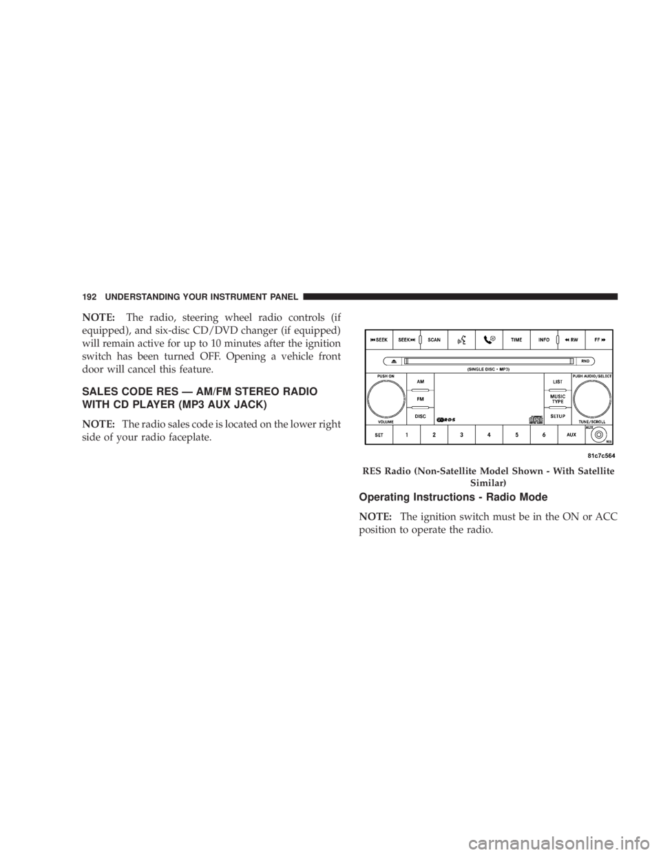
SALES CODE RES Ð AM/FM STEREO RADIO
WITH CD PLAYER (MP3 AUX JACK)
NOTE: The radio sales code is located on the lower right
side of your radio faceplate.
Operating Instructions - Radio Mode
NOTE: The ignition switch must be in the ON or ACC
position to operate the radio. RES Radio (Non-Satellite Model Shown - With Satellite
Similar)192 UNDERSTANDING YOUR INSTRUMENT PANEL
Page 309 of 467
Keep dismounted tires in a cool, dry place with as little
exposure to light as possible. Protect tires from contact
with oil, grease, and gasoline.
Replacement Tires
The tires on your new vehicle provide a balance of many
characteristics. They should be inspected regularly for
wear and correct cold tire inflation pressure. The manu-
facturer strongly recommends that you use tires equiva-
lent to the originals in size, quality and performance
when replacement is needed (refer to the paragraph on
ªTread Wear Indicatorsº). Refer to the ªTire and Loading
Informationº placard for the size designation of your tire.
The service description and load identification will be
found on the original equipment tire. Failure to use
equivalent replacement tires may adversely affect the
safety, handling, and ride of your vehicle. We recommend
that you contact your original equipment or an autho-
rized tire dealer with any questions you may have on tire
specifications or capability. WARNING!Do not use a tire, wheel size or rating other than that
specified for your vehicle. Some combinations of
unapproved tires and wheels may change suspension
dimensions and performance characteristics, result-
ing in changes to steering, handling, and braking of
your vehicle. This can cause unpredictable handling
and stress to steering and suspension components.
You could lose control and have an accident resulting
in serious injury or death. Use only the tire and
wheel sizes with load ratings approved for your
vehicle. STARTING AND OPERATING 307
5
Page 315 of 467
² Seasonal temperature changes will affect tire pressure,
and the TPMS will monitor the actual tire pressure in
the tire.
BASE SYSTEM Ð IF EQUIPPED
The Tire Pressure Monitor System (TPMS) uses wireless
technology with wheel rim mounted electronic sensors to
monitor tire pressure levels. Sensors, mounted to each
wheel as part of the valve stem, transmit tire pressure
readings to the Receiver Module.
NOTE: It is particularly important for you to check the
tire pressure in all of the tires on your vehicle monthly
and to maintain the proper pressure.
The TPMS consists of the following components:
² Receiver Module
² Four Tire Pressure Monitoring Sensors
² Tire Pressure Monitoring Telltale Light Tire Pressure Monitoring Low Pressure Warnings
The Tire Pressure Monitoring Telltale Light will
illuminate in the instrument cluster and a chime
will sound when tire pressure is low in one or
more of the four active road tires. Should this occur, you
should stop as soon as possible, check the inflation
pressure of each tire on your vehicle, and inflate each tire
to the vehicle's recommended cold placard pressure
value. Once the system receives the updated tire pres-
sures, the system will automatically update and the Tire
Pressure Monitoring Telltale Light will turn off. The
vehicle may need to be driven for up to 10 minutes above
15 mph (25 km/h) in order for the TPMS to receive this
information.
Check TPMS Warning
The Tire Pressure Monitoring Telltale Light will flash on
and off for 75 seconds and then remain on solid when a
system fault is detected. The system fault will also sound
a chime. If the ignition key is cycled, this sequence will STARTING AND OPERATING 313
5
Page 354 of 467
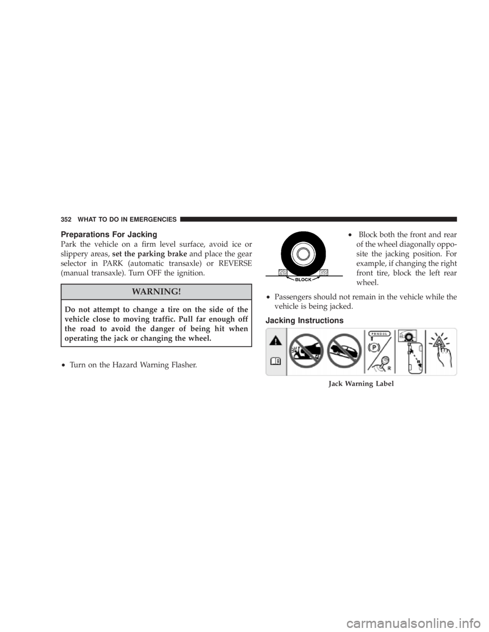
Preparations For Jacking
Park the vehicle on a firm level surface, avoid ice or
slippery areas, set the parking brake and place the gear
selector in PARK (automatic transaxle) or REVERSE
(manual transaxle). Turn OFF the ignition.
WARNING!Do not attempt to change a tire on the side of the
vehicle close to moving traffic. Pull far enough off
the road to avoid the danger of being hit when
operating the jack or changing the wheel.
² Turn on the Hazard Warning Flasher. ² Block both the front and rear
of the wheel diagonally oppo-
site the jacking position. For
example, if changing the right
front tire, block the left rear
wheel.
² Passengers should not remain in the vehicle while the
vehicle is being jacked.
Jacking Instructions
Jack Warning Label352 WHAT TO DO IN EMERGENCIES
Page 358 of 467
3. There are two front jacking locations and two rear
jacking locations on each side of the body as shown.
CAUTION!Do not attempt to raise the vehicle by jacking on
locations other than those indicated in step 3.
4. Turn the jack screw to the left until the jack can be
placed under the jacking location. Once the jack is
positioned, turn the jack screw to the right until the jack
head is properly engaged with the lift area closest to the
wheel to be changed. Do not raise the vehicle until you
are sure the jack is securely engaged. WARNING!Raising the vehicle higher than necessary can make
the vehicle less stable. It could slip off the jack and
hurt someone near it. Raise the vehicle only enough
to remove the tire.
5. Raise the vehicle by turning the jack screw to the right,
using the swivel wrench. Raise the vehicle only until the
tire just clears the surface and enough clearance is
obtained to install the spare tire. Minimum tire lift
provides maximum stability.
6. Remove the wheel nuts, and pull the wheel and wheel
covers (where applicable) off the hub. Install the spare
wheel and wheel nuts with the cone shaped end of the
nuts toward the wheel. Lightly tighten the nuts. To avoid
the risk of forcing the vehicle off the jack, do not tighten
the nuts fully until the vehicle has been lowered.356 WHAT TO DO IN EMERGENCIES
Page 459 of 467

Radio (Sound Systems) ................. 220,223
Rear Cup Holder ........................ 159
Rear Seat, Folding .................... 126,127
Rear Wheel Bearings ..................... 400
Rear Window Defroster ................... 256
Rear Window Features .................... 256
Rearview Mirrors ........................ 85
Recorder, Event Data ...................... 65
Recreational Towing ................... 345,363
Reformulated Gasoline .................... 320
Refrigerant ............................ 383
Reminder, Seat Belt ..................... 48,49
Remote Control
Door Locks ........................... 21
Security Alarm ......................... 18
Remote Keyless Entry (RKE) ................. 21
Remote Keyless Entry (Sedan) ............... 21
Remote Sound System (Radio) Controls ........ 236
Remote Starting System .................... 28 Remote Trunk Release ..................... 39
Replacement Bulbs ....................... 411
Replacement Keys ........................ 16
Replacement Parts ....................... 373
Replacement Tires ....................... 307
Reporting Safety Defects ................... 439
Resetting Oil Change Indicator ........... 173,184
Restraint, Head ......................... 125
Restraints, Child ......................... 67
Restraints, Infant ......................... 68
Rotation, Tires .......................... 309
Safety Checks Inside Vehicle ................. 79
Safety Checks Outside Vehicle ............... 80
Safety Defects, Reporting .................. 439
Safety Information, Tire ................... 291
Safety Tips ............................. 78
Satellite Radio ............... 220,221,223,224,231
Satellite Radio Antenna ................... 233 INDEX 457
10