ignition DODGE AVENGER 2010 2.G Owner's Manual
[x] Cancel search | Manufacturer: DODGE, Model Year: 2010, Model line: AVENGER, Model: DODGE AVENGER 2010 2.GPages: 76, PDF Size: 11.78 MB
Page 44 of 76
Fuel Cap/Loose Gas Cap Message
• If a “gas cap” message (shown as gASCAP) appears, tighten the gas cap until a“clicking” sound is heard.
• Press the odometer reset button to turn the message off.
• If the message continues to appear for mor e than three days after tightening the gas
cap, see your authorized dealer.
Oil Change Indicator
Message
• If an “oil change” message (shown as CHAngE OIL) appears and a single chime
sounds, it is time for your next required oil change.
Resetting The Light After Servicing
• Turn the ignition switch to the ON/RUN position (do not start engine).
• Fully depress the accelerator pedal three times within 10 seconds.
• Turn the ignition switch to the OFF/LOCK position.
IF YOUR ENGINE OVERHEATS
• In any of the following situations, you c an reduce the potential for overheating by
taking the appropriate action.
• On the highways — slow down.
• In city traffic — while stopped, shift tran smission intoNEUTRAL, but do not increase
engine idle speed.
NOTE: There are steps that you can take to slow down an impending overheat
condition:
• If your air conditioner (A/C) is on, turn it off. The A/C system adds heat to the engine cooling system and turning the A/C off can help remove this heat.
• You can also turn the Temperature Control to maximum heat, the Mode Control to floor and the Fan Control to high. This allows the heater core to act as a supplement to the
radiator and aids in removing heat from the engine cooling system.
• If the temperature reading does not re turn to normal, turn the engine off immediately.
• We recommend that you do not operate the vehicle or engine damage will occur. Have the vehicle serviced immediately.
CAUTION!
Driving with a hot cooling system could dama ge your vehicle. If the temperature gauge
reads HOT (H), pull over and stop the vehicle. Idle the vehicle with the air conditioner
turned off until the pointer drops back into the normal range. If the pointer remains on
HOT (H), and you hear continuous chimes, t urn the engine off immediately, and call
for service.
WHAT TO DO IN EMERGENCIES
42
Page 47 of 76
• Set the parking brake and shiftthe automatic transmissioninto PARK.
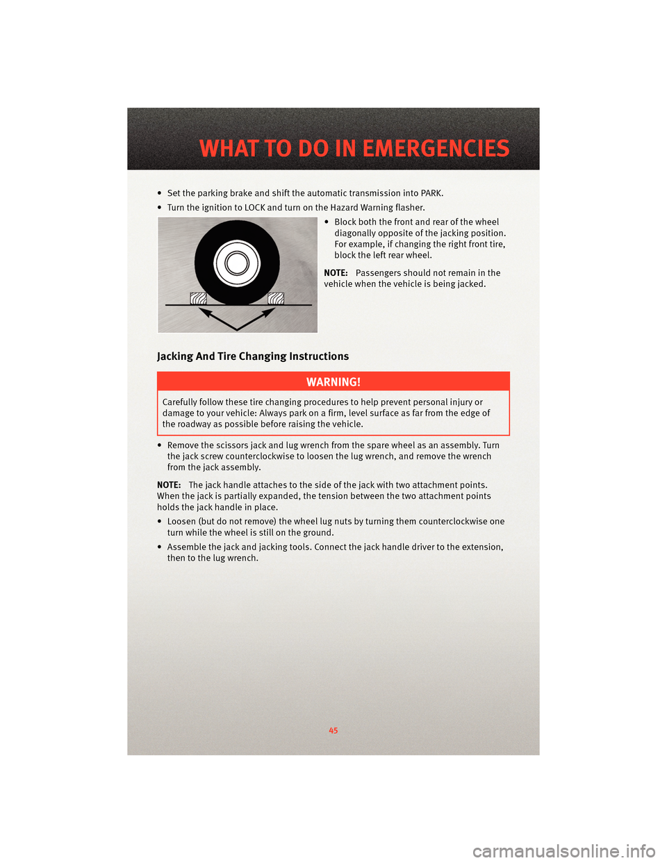
• Turn the ignition to LOCK and turn on the Hazard Warning flasher. • Block both the front and rear of the wheeldiagonally opposite of the jacking position.
For example, if changing the right front tire,
block the left rear wheel.
NOTE: Passengers should not remain in the
vehicle when the vehicle is being jacked.
Jacking And Tire Changing Instructions
WARNING!
Carefully follow these tire changing p rocedures to help prevent personal injury or
damage to your vehicle: Always park on a firm, level surface as far from the edge of
the roadway as possible before raising the vehicle.
• Remove the scissors jack and lug wrench from the spare wheel as an assembly. Turn the jack screw countercloc kwise to loosen the lug wrench, and remove the wrench
from the jack assembly.
NOTE: The jack handle attaches to the side of the jack with two attachment points.
When the jack is partially expanded, the tension between the two attachment points
holds the jack handle in place.
• Loosen (but do not remove) the wheel lug nuts by turning them counterclockwise one
turn while the wheel is still on the ground.
• Assemble the jack and jacking tools. Connect the jack handle driver to the extension, then to the lug wrench.
45
WHAT TO DO IN EMERGENCIES
Page 50 of 76
WARNING!
When temperatures are below the freezing point, electrolyte in a discharged battery
may freeze. Do not attempt jump-startingbecause the battery could rupture or
explode and cause personal injury. Battery temperature must be brought above the
freezing point before attempting a jump-start.
Preparations for Jump-Start
• The battery in your vehicle is located between the left front headlight assembly and
the left front wheel splash shield. To allow jump-starting there are remote battery
posts located on the left side of the engine compartment.
WARNING!
• Take care to avoid the radiator coolin g fan whenever the hood is raised. It can start
anytime the ignition switch is on. You can be injured by moving fan blades.
• Remove any metal jewelry, such as watch bands or bracelets, that might make an inadvertent electrical contact. You could be seriously injured.
• Batteries contain sulfuric acid that can burn your skin or eyes and generate hydrogen gas which is flammable and explosive. Keep open flames or sparks away
from the battery.
• Set the parking brake, shift the autom atic transmission into PARK and turn the ignition
to LOCK.
• Turn off the heater, radio, and all unnecessary electrical accessories.
• Remove the protective cover over the remote positive(+)battery post. To remove the
cover, press the locking tab and pull upward on the cover.
• If using another vehicle to jump-start the battery, park the vehicle within the jumper cables reach, set the parking brake and make sure the ignition is OFF.
WARNING!
WARNING! Do not allow vehicles to touch each other as this could establish a ground
connection and personal injury could result.
WHAT TO DO IN EMERGENCIES
48
Page 64 of 76
FUSES
TotallyIntegrated Power Module (TIPM)
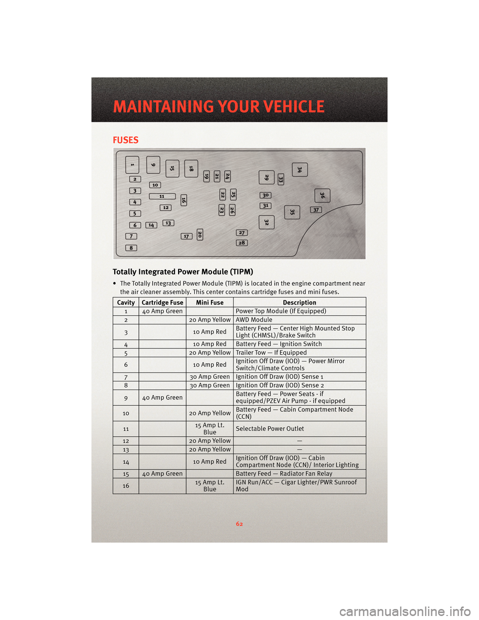
• The Totally Integrated Power Module (TIPM) is located in the engine compartment near
the air cleaner assembly. This center contains cartridge fuses and mini fuses.
Cavity Cartridge Fuse Mini Fuse Description
1 40 Amp Green Power Top Module (If Equipped)
2 20 Amp Yellow AWD Module
3 10 Amp RedBattery Feed — Center High Mounted Stop
Light (CHMSL)/Brake Switch
4 10 Amp Red Battery Feed — Ignition Switch
5 20 Amp Yellow Trailer Tow — If Equipped
6 10 Amp RedIgnition Off Draw (IOD) — Power Mirror
Switch/Clim
ate Controls
7 30 Amp Green Ignition Off Draw (IOD) Sense 1
8 30 Amp Green Ignition Off Draw (IOD) Sense 2
9 40 Amp Green Battery Feed — Power Seats - if
equipped/PZEV Air Pump - if equipped
10 20 Amp YellowBattery Feed — Cabin Compartment Node
(CCN)
11 15 Amp Lt.
Blue Selectable Power Outlet
12 20 Amp Yellow —
13 20 Amp Yellow —
14 10 Amp RedIgnition Off Draw (IOD) — Cabin
Compartment Node (CCN)/ Interior Lighting
15 40 Amp Green Battery Feed — Radiator Fan Relay
16 15 Amp Lt.
Blue IGN Run/ACC — Cigar Lighter/PWR Sunroof
Mod
MAINTAINING YOUR VEHICLE
62
Page 65 of 76
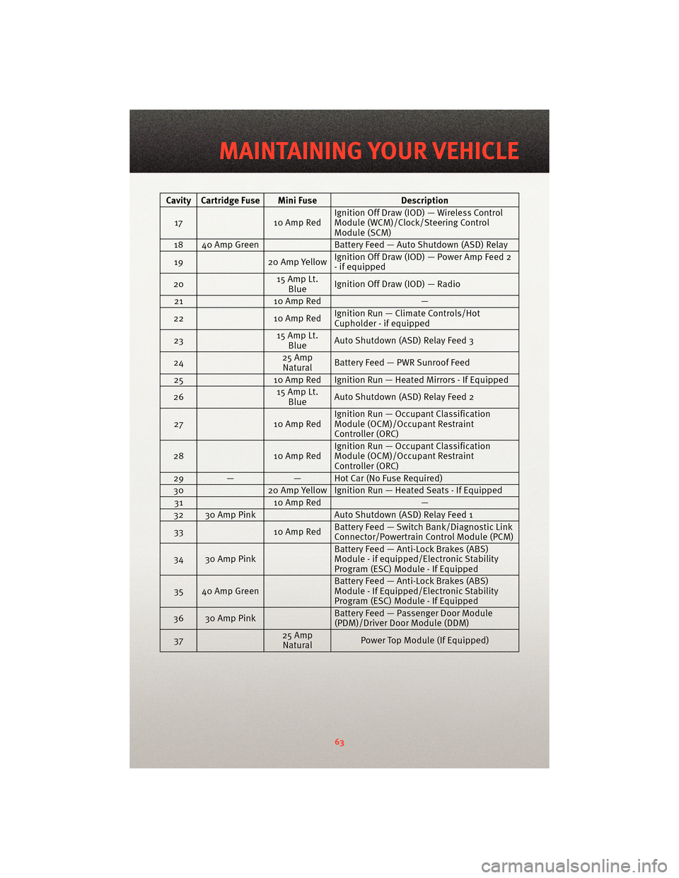
Cavity Cartridge Fuse Mini FuseDescription
17 10 Amp RedIgnition Off Draw (IOD) — Wireless Control
Module (WCM)/Clock/Steering Control
Module (SCM)
18 40 Amp Green Battery Feed — Auto Shutdown (ASD) Relay
19 20 Amp YellowIgnition Off Draw (IOD) — Power Amp Feed 2
- if equipped
20 15 Amp Lt.
Blue Ignition Off Draw (IOD) — Radio
21 10 Amp Red —
22 10 Amp RedIgnition Run — Climate Controls/Hot
Cupholder - if equipped
23 15 Amp Lt.
Blue Auto Shutdown (ASD) Relay Feed 3
24 25 Amp
Natural Battery Feed — PWR Sunroof Feed
25 10 Amp Red Ignition Run — Heated Mirrors - If Equipped
26 15 Amp Lt.
Blue Auto Shutdown (ASD) Relay Feed 2
27 10 Amp RedIgnition Run — Occup
ant Classification
Module (OCM)/Occupant Restraint
Controller (ORC)
28 10 Amp RedIgnition Run — Occup
ant Classification
Module (OCM)/Occupant Restraint
Controller (ORC)
29 — — Hot Car (No Fuse Required)
30 20 Amp Yellow Ignition Run — Heated Seats - If Equipped
31 10 Amp Red —
32 30 Amp Pink Auto Shutdown (ASD) Relay Feed 1
33 10 Amp RedBattery Feed — Switch Bank/Diagnostic Link
Connector/Powertrain Control Module (PCM)
34 30 Amp Pink Battery Feed — Anti-Lock Brakes (ABS)
Module - if equipped/Electronic Stability
Program (ESC) Module - If Equipped
35 40 Amp Green Battery Feed — Anti-Lock Brakes (ABS)
Module - If Equipped/Electronic Stability
Program (ESC) Module - If Equipped
36 30 Amp Pink Battery Feed — Passenger Door Module
(PDM)/Driver Door Module (DDM)
37 25 Amp
Natural Power Top Module (If Equipped)
63
MAINTAINING YOUR VEHICLE