change wheel DODGE CALIBER 2006 1.G Owners Manual
[x] Cancel search | Manufacturer: DODGE, Model Year: 2006, Model line: CALIBER, Model: DODGE CALIBER 2006 1.GPages: 322, PDF Size: 5.99 MB
Page 114 of 322

CAUTION!
The TPMS has been optimized for the original
equipment tires and wheels. TPMS pressures and
warning have been established for the tire size
equipped on your vehicle. Undesirable system op-
eration or sensor damage may result when using
replacement equipment that is not of the same size,
type, and/or style. Aftermarket wheels can cause
sensor damage. Do not use tire sealant from a can, or
balance beads if your vehicle is equipped with a
TPMS, as damage to the sensors may result.
15. Odometer/Trip Odometer
A vacuum fluorescent display indicates the total distance
the vehicle has been driven. Also, the cluster will display,
replacing the odometer/trip odometer, vehicle warning
messages such as: door/gate ajar and loose gas cap.
Loose gas cap will be displayed from the Odometer/Trip
Odometer on all models.
NOTE:If vehicle is equipped with the optional Elec-
tronic Vehicle Information Center (EVIC) in the instru-
ment cluster, all warnings including ªdoorº, and ªgATEº
will only be displayed in the EVIC display. For additional
information, refer to ªElectronic Vehicle Information Cen-
ter Ð If Equippedº in Section 3.
U.S. federal regulations require that upon transfer of
vehicle ownership, the seller certify to the purchaser the
correct mileage that the vehicle has been driven. There-
fore, if the odometer reading is changed during repair or
replacement, be sure to keep a record of the reading
before and after the service so that the correct mileage can
be determined.
16. Malfunction Indicator Light
This light is part of an onboard diagnostic
system called OBD that monitors emissions,
engine, and automatic transmission control
systems. The light will illuminate when the key is in
the ON/RUN position before engine start. If the bulb
does not come on when turning the key from OFF to
ON/RUN, have the condition checked promptly.
114 UNDERSTANDING YOUR INSTRUMENT PANEL
Page 117 of 322

ignition key is turned to the ON position and may stay
on for as long as four seconds.
If the ABS light remains on or comes on during driving,
it indicates that the Anti-Lock portion of the brake system
is not functioning and that service is required, however,
the conventional brake system will continue to operate
normally provided that the BRAKE warning light is not
on.
If the ABS light is on, the brake system should be serviced
as soon as possible to restore the benefit of Anti-Lock
Brakes.
The warning light should be checked frequently to assure
that it is operating properly. Turn the ignition key to the
on position, but do not start the vehicle. The light should
come on. If the light does not come on, have the system
checked by an authorized dealer.
26. High Beam Indicator
This light shows that the headlights are on high
beam. Push the turn signal lever away from the
steering wheel to switch the headlights from high or
low beam.27. Brake System Warning Light
This light monitors various brake functions,
including brake fluid level and parking brake
application. If the brake light turns on, it may indicate
that the parking brake is applied, there is a low brake
fluid level or there is a problem with the anti-lock
brake system.
The dual brake system provides a reserve braking capac-
ity in the event of a failure to a portion of the hydraulic
system. Failure of either half of the dual brake system is
indicated by the Brake Warning Light which will turn on
when the brake fluid level in the master cylinder has
dropped below a specified level.
The light will remain on until the cause is corrected.
NOTE:The light may flash momentarily during sharp
cornering maneuvers which change fluid level condi-
tions. The vehicle should have service performed, and
the brake fluid level checked.
If brake failure is indicated, immediate repair is neces-
sary.
UNDERSTANDING YOUR INSTRUMENT PANEL 117
4
Page 128 of 322

Two Types of Signals
There are two basic types of radio signals... AM or
Amplitude Modulation, in which the transmitted sound
causes the amplitude, or height, of the radio waves to
vary... and FM or Frequency Modulation, in which the
frequency of the wave is varied to carry the sound.
Electrical Disturbances
Radio waves may pick up electrical disturbances during
transmission. They mainly affect the wave amplitude,
and thus remain a part of the AM reception. They
interfere very little with the frequency variations that
carry the FM signal.
AM Reception
AM sound is based on wave amplitude, so AM reception
can be disrupted by such things as lightning, power lines
and neon signs.
FM Reception
Because FM transmission is based on frequency varia-
tions, interference that consists of amplitude variations
can be filtered out, leaving the reception relatively clear,
which is the major feature of FM radio.
NOTE:On vehicles so equipped the radio, steering
wheel radio controls and 6 disc CD/DVD changer will
remain active for up to 45 seconds after the ignition
switch has been turned off. Opening a vehicle front door
will cancel this feature.
ELECTRONIC DIGITAL CLOCK
The clock and radio each use the display panel built into
the radio. A digital readout shows the frequency and/or
time in hours and minutes (depending on your radio
model) whenever the ignition switch is in the ªONº or
ªACCº position.
When the ignition switch is in the ªOFFº position, or
when the radio frequency is being displayed, time keep-
ing is accurately maintained.
On the AM/FM/CD (6-disc) radio the time button alter-
nates the location of the time and frequency on the
display. On the AM/FM/CD (single-disc) radio only one
of the two, time or frequency is displayed.
128 UNDERSTANDING YOUR INSTRUMENT PANEL
Page 161 of 322

PTY Button(SEEK(
When the desired program is obtained, press the9SEEK9
button within five seconds. The channel will change to
the next channel that matches the program type selected.
Satellite Antenna
To ensure optimum reception, do not place items on the
roof around the rooftop antenna location. Metal objects
placed within the line of sight of the antenna will cause
decreased performance. Larger luggage items should be
placed as far forward as possible. Do not place items
directly on or above the antenna. The luggage rack (if
equipped), should also not be positioned directly above
the antenna.
Reception Quality
Satellite reception may be interrupted due to one of the
following reasons.
²The vehicle is parked in an underground parking
structure or under a physical obstacle.
²Dense tree coverage may interrupt reception in the
form of short audio mutes.
²Driving under wide bridges or along tall buildings can
cause intermittent reception.
²Placing objects over or too close to the antenna can
cause signal blockage.
REMOTE SOUND SYSTEM CONTROLS Ð IF
EQUIPPED
The remote sound system controls are located on the rear
surface of the steering wheel. Reach behind the wheel to
access the switches.
UNDERSTANDING YOUR INSTRUMENT PANEL 161
4
Page 205 of 322

WARNING!
²Do not use a tire, wheel size or rating other than
that specified for your vehicle. Some combina-
tions of unapproved tires and wheels may change
suspension dimensions and performance charac-
teristics, resulting in changes to steering, han-
dling, and braking of your vehicle. This can cause
unpredictable handling and stress to steering and
suspension components. You could lose control
and have an accident resulting in serious injury or
death. Use only the tire and wheel sizes with load
ratings approved for your vehicle.
²Never use a tire with a smaller load index or
capacity, other than what was originally equipped
on your vehicle. Using a tire with a smaller load
index could result in tire overloading and failure.
You could lose control and have an accident.
²Failure to equip your vehicle with tires having
adequate speed capability can result in sudden
tire failure and loss of vehicle control.
CAUTION!
Replacing original tires with tires of a different size
may result in false speedometer and odometer read-
ings.
Alignment And Balance
Poor suspension alignment may result in:
²Fast tire wear.
²Uneven tire wear, such as feathering and one-sided
wear.
²Vehicle pull to right or left.
Tires may also cause the vehicle to pull to the left or right.
Alignment will not correct this condition. See your dealer
for proper diagnosis.
Improper alignment will not cause vehicle vibration.
Vibration may be a result of tire and wheel out-of-
balance. Proper balancing will reduce vibration and
avoid tire cupping and spotty wear.
STARTING AND OPERATING 205
5
Page 231 of 322

Preparations For Jacking
Park the vehicle on a firm level surface, avoid ice or
slippery areas,set the parking brakeand place the gear
selector in PARK (automatic transaxle) or REVERSE
(manual transaxle). Turn OFF the ignition.
WARNING!
Do not attempt to change a tire on the side of the
vehicle close to moving traffic. Pull far enough off
the road to avoid the danger of being hit when
operating the jack or changing the wheel.
²Turn on the Hazard Warning Flasher.
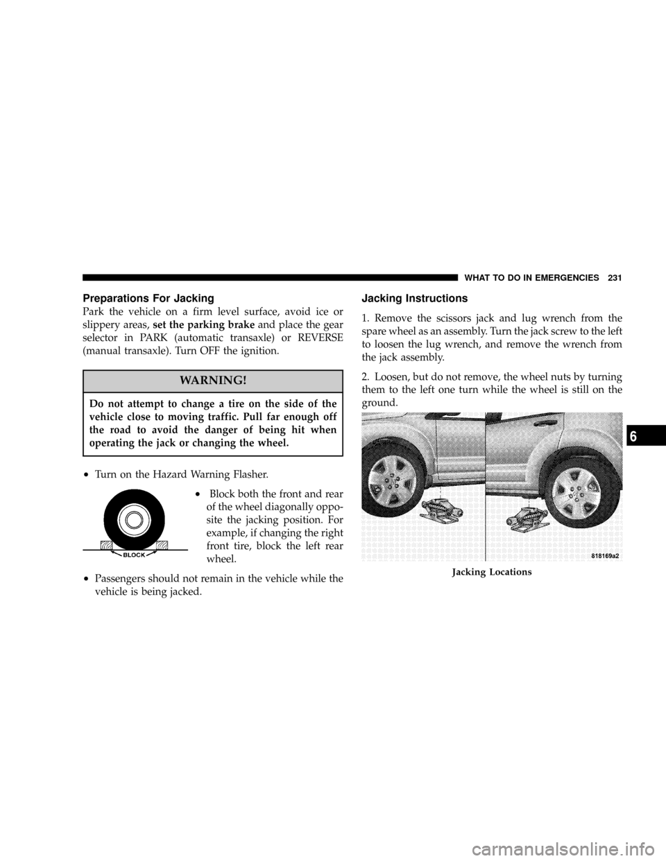
²Block both the front and rear
of the wheel diagonally oppo-
site the jacking position. For
example, if changing the right
front tire, block the left rear
wheel.
²Passengers should not remain in the vehicle while the
vehicle is being jacked.
Jacking Instructions
1. Remove the scissors jack and lug wrench from the
spare wheel as an assembly. Turn the jack screw to the left
to loosen the lug wrench, and remove the wrench from
the jack assembly.
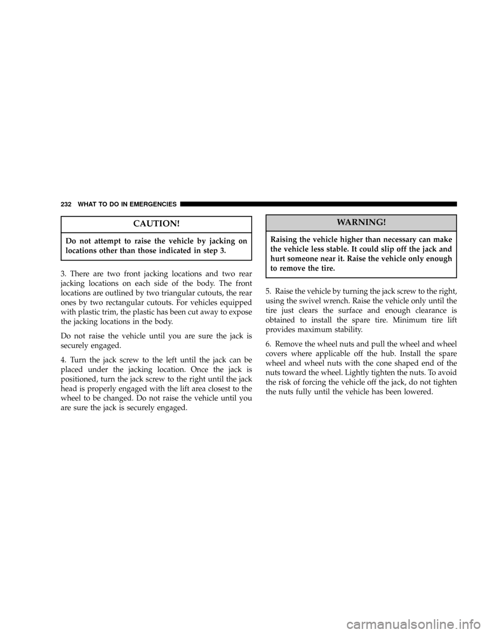
2. Loosen, but do not remove, the wheel nuts by turning
them to the left one turn while the wheel is still on the
ground.
Jacking Locations
WHAT TO DO IN EMERGENCIES 231
6
Page 232 of 322

CAUTION!
Do not attempt to raise the vehicle by jacking on
locations other than those indicated in step 3.
3. There are two front jacking locations and two rear
jacking locations on each side of the body. The front
locations are outlined by two triangular cutouts, the rear
ones by two rectangular cutouts. For vehicles equipped
with plastic trim, the plastic has been cut away to expose
the jacking locations in the body.
Do not raise the vehicle until you are sure the jack is
securely engaged.
4. Turn the jack screw to the left until the jack can be
placed under the jacking location. Once the jack is
positioned, turn the jack screw to the right until the jack
head is properly engaged with the lift area closest to the
wheel to be changed. Do not raise the vehicle until you
are sure the jack is securely engaged.
WARNING!
Raising the vehicle higher than necessary can make
the vehicle less stable. It could slip off the jack and
hurt someone near it. Raise the vehicle only enough
to remove the tire.
5. Raise the vehicle by turning the jack screw to the right,
using the swivel wrench. Raise the vehicle only until the
tire just clears the surface and enough clearance is
obtained to install the spare tire. Minimum tire lift
provides maximum stability.
6. Remove the wheel nuts and pull the wheel and wheel
covers where applicable off the hub. Install the spare
wheel and wheel nuts with the cone shaped end of the
nuts toward the wheel. Lightly tighten the nuts. To avoid
the risk of forcing the vehicle off the jack, do not tighten
the nuts fully until the vehicle has been lowered.
232 WHAT TO DO IN EMERGENCIES
Page 263 of 322

WARNING!
Overfilling the brake fluid reservoir can result in
spilling brake fluid on hot engine parts and the
brake fluid catching fire.
Use only brake fluid that has been in a tightly closed
container to avoid contamination from foreign matter.
Do not allow petroleum based fluid to contaminate the
brake fluid as seal damage will result!
Automatic Transaxle
All front wheel drive vehicles have a transmission and
differential assembly contained within a single housing.
Selection Of Lubricant
It is important that the proper lubricant is used in the
transaxle to assure optimum transaxle performance. Use
only the manufacturer's recommended transmission
fluid which has been formulated with special metal to
metal friction coefficient additives to provide the propersteel belt traction on the drive and driven pulleys. Refer
to Fluids, Lubricants and Genuine Parts for correct fluid
type.
CAUTION!
Using a transmission fluid other than the manufac-
turers recommended fluid will cause belt slip and
result in a complete transmission failure! Refer to
Fluids, Lubricants and Genuine Parts for correct
fluid type.
Fluid Level Check
The fluid level in the automatic transaxle should be
checked only by a trained technician.
Fluid and Filter Changes
Refer to the ªMaintenance Schedule located if section 8 of
this manual for the correct change interval for your type
of driving.
MAINTAINING YOUR VEHICLE 263
7