warning light DODGE CALIBER 2009 1.G User Guide
[x] Cancel search | Manufacturer: DODGE, Model Year: 2009, Model line: CALIBER, Model: DODGE CALIBER 2009 1.GPages: 431, PDF Size: 3.12 MB
Page 128 of 431
CAUTION!
To prevent possible damage, do not slam the hood to
close it. Lower the hood until it is open approxi-
mately 8 in (20 cm) and then drop it. This should
secure both latches. Never drive your vehicle unless
the hood is fully closed, with both latches engaged.
WARNING!
If the hood is not fully latched it could fly up when
the vehicle is moving and block your forward vision.
You could have a collision. Be sure all hood latches
are fully latched before driving.
LIGHTS
Multifunction Lever
The multifunction lever controls the operation of the
headlights, parking lights, turn signals, headlight beam
selection, instrument panel light dimming, interior lights,
the passing lights, and fog lights. The multifunction lever
is located on the left side of the steering column.
Headlights, Parking Lights and Instrument Panel
Lights
Turn the end of the multifunction lever to the first detent
for parking light operation. Turn the multifunction lever
to the second detent for headlight operation.
126 UNDERSTANDING THE FEATURES OF YOUR VEHICLE
Page 133 of 431
Daytime Running Lights (DRL) — If Equipped
The high beam headlights will come on as Daytime
Running Lights (DRL) at DRL intensity, which is a lower
intensity then the normal high beams. The DRL’s will
come on whenever the ignition is ON, the engine is
running, the headlight switch is off, the parking brake is
off, the turn signal is off, and the shift lever is in any
position except for PARK.
NOTE:The DRLs will automatically turn off when the
turn signals or Hazard Warning flashers are in operation
and automatically turn back on when the turn signals
and Hazard Warning flashers are not operating.
WINDSHIELD WIPERS AND WASHERS
The wipers and washers are operated by a switch
on the control lever. The lever is located on the
right side of the steering column.
Windshield Wiper Operation
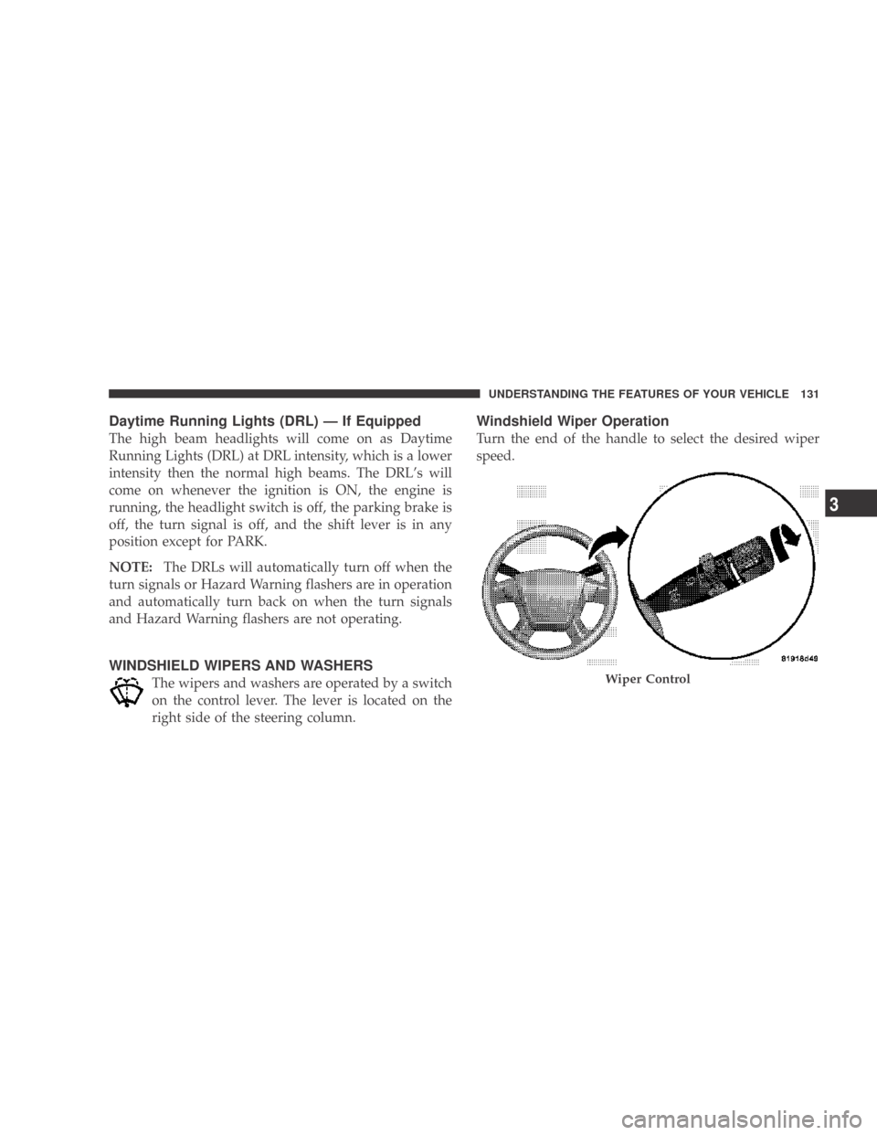
Turn the end of the handle to select the desired wiper
speed.
Wiper Control
UNDERSTANDING THE FEATURES OF YOUR VEHICLE 131
3
Page 139 of 431
Tapping the SET DECEL button once will result in a
1 mph (1.6 km/h) speed decrease. Each time the button is
tapped, speed decreases.
Manual Transaxle
Pressing the clutch pedal will disengage the speed con-
trol. A slight increase in engine RPM before the Electronic
Speed Control disengages is normal.
Vehicles equipped with manual transaxles may need to
be shifted into a lower gear to climb hills without speed
loss.
WARNING!
Electronic Speed Control can be dangerous where the
system cannot maintain a constant speed. Your ve-
hicle could go too fast for the conditions, and you
could lose control. An accident could be the result.
Do not use Electronic Speed Control in heavy traffic
or on roads that are winding, icy, snow-covered, or
slippery.
To Accelerate For Passing
Press the accelerator as you would normally. When the
pedal is released, the vehicle will return to the set speed.
Using Electronic Speed Control On Hills
NOTE:The Electronic Speed Control system maintains
speed, up and down hills. A slight speed change on
moderate hills is normal.
UNDERSTANDING THE FEATURES OF YOUR VEHICLE 137
3
Page 151 of 431
WARNING!
To avoid serious injury or death:
•Do not use a three-prong adapter.
•Do not insert any objects into the receptacles.
•Do not touch with wet hands.
•Close the lid when not in use and while driving
the vehicle.
•If this outlet is mishandled, it may cause an
electric shock and failure.
CAUTION!
•Many accessories that can be plugged in draw
power from the vehicle’s battery, even when not in
use (i.e., cellular phones, etc.). Eventually, if
plugged in long enough, the vehicle’s battery will
discharge sufficiently to degrade battery life
and/or prevent engine starting.
•Accessories that draw higher power (i.e., coolers,
vacuum cleaners, lights, etc.) will degrade the
battery even more quickly. Only use these inter-
mittently and with great caution.
•After the use of high power draw accessories, or
long periods of the vehicle not being started (with
accessories still plugged in), the vehicle must be
driven a sufficient length of time to allow the
generator to recharge the vehicle’s battery.
UNDERSTANDING THE FEATURES OF YOUR VEHICLE 149
3
Page 153 of 431
WARNING!
To avoid serious injury or death:
•Do not use a three-prong adaptor.
•Do not insert any objects into the receptacles.
•Do not touch with wet hands.
•Close the lid when not in use.
•If this outlet is mishandled, it may cause an
electric shock and failure.
CAUTION!
•Many accessories that can be plugged in draw
power from the vehicle’s battery, even when not in
use (i.e., cellular phones, etc.). Eventually, if
plugged in long enough, the vehicle’s battery will
discharge sufficiently to degrade battery life
and/or prevent engine starting.
(Continued)
CAUTION! (Continued)
•Accessories that draw higher power (i.e., coolers,
vacuum cleaners, lights, etc.) will degrade the
battery even more quickly. Only use these inter-
mittently and with great caution.
•After the use of high power draw accessories, or
long periods of the vehicle not being started (with
accessories still plugged in), the vehicle must be
driven a sufficient length of time to allow the
generator to recharge the vehicle’s battery.
UNDERSTANDING THE FEATURES OF YOUR VEHICLE 151
3
Page 172 of 431
WARNING!
A hot engine cooling system is dangerous. You or
others could be badly burned by steam or boiling
coolant. You may want to call an authorized dealer-
ship for service if your vehicle overheats. If you
decide to look under the hood yourself, see Section 7
of this manual. Follow the warnings under the Cool-
ing System Pressure Cap paragraph.
4. Speedometer
The Speedometer shows the vehicle speed in miles per
hour and/or kilometers per hour (mph/kph).
5. Tachometer
The white area of the scale shows the permissible engine
revolutions-per-minute (RPM x 1000) for each gear range.
Before reaching the red area, ease up on the accelerator to
prevent engine damage. 6. Low Fuel Light
When the fuel level reaches approximately 2.0 gal
(7.8 L) this light will turn on, and remain on until
fuel is added.
7. Charging System Light This light shows the status of the electrical charg-
ing system. The light should come on when the
ignition switch is first turned ON and remain on briefly
as a bulb check. If the light stays on or comes on while
driving, turn off some of the vehicle’s non-essential
electrical devices or increase engine speed (if at idle). If
the charging system light remains on, it means that the
vehicle is experiencing a problem with the charging
system. Obtain SERVICE IMMEDIATELY. See an autho-
rized dealer.
170 UNDERSTANDING YOUR INSTRUMENT PANEL
Page 173 of 431
8. Airbag Warning LightThis light turns on and remains on for seven
seconds as a bulb check, when the ignition
switch is first turned ON. If the light is not on
during starting, stays on, or turns on while
driving, have the system inspected by an authorized
dealer as soon as possible.
9. Vehicle Security Light — If Equipped This light will flash at a fast rate for approxi-
mately 16 seconds, when the vehicle security
alarm is arming, and then will flash slowly
until the vehicle is disarmed.
10. Seat Belt Reminder Light When the ignition switch is first turned ON, this
light will turn on for five to eight seconds as a bulb
check. During the bulb check, if the driver’s seat belt is unbuckled, a chime will sound. After the bulb
check or when driving, if the driver’s seat belt remains
unbuckled, the Seat Belt Reminder Light will illuminate
and the chime will sound. Refer to “Occupant Restraints”
in Section 2 for more information.
11. Oil Pressure Warning Light
This light indicates low engine oil pressure. The
light should turn on momentarily when the engine
is started. If the light turns on while driving, stop the
vehicle and shut off the engine as soon as possible. A
chime will sound for four minutes when this light turns
on.
Do not operate the vehicle until the cause is corrected.
This light does not show how much oil is in the engine.
The engine oil level must be checked under the hood.
UNDERSTANDING YOUR INSTRUMENT PANEL 171
4
Page 174 of 431
12. Engine Temperature Warning LightThis light warns of an overheated engine condi-
tion. As temperatures rise and the gauge ap-
proaches H, this indicator will illuminate and a
single chime will sound after reaching a set threshold.
Further overheating will cause the temperature gauge to
pass H, the indicator will continuously flash and a
continuous chime will occur until the engine is allowed
to cool.
If the light turns on while driving, safely pull over and
stop the vehicle. If the A/C system is on, turn it off. Also,
shift the transmission into NEUTRAL and idle the ve-
hicle. If the temperature reading does not return to
normal, turn the engine off immediately and call for
service. Refer to “If Your Engine Overheats” in Section 6
for more information. 13. Shift Lever Indicator
This display indicator shows the automatic transmission
shift lever selection.
14. Tire Pressure Monitoring Telltale Light
Each tire, including the spare (if provided),
should be checked monthly, when cold and
inflated to the inflation pressure recommended
by the vehicle manufacturer on the vehicle
placard or tire inflation pressure label. (If your vehicle
has tires of a different size than the size indicated on the
vehicle placard or tire inflation pressure label, you should
determine the proper tire inflation pressure for those
tires.)
As an added safety feature, your vehicle has been
equipped with a Tire Pressure Monitoring System
(TPMS) that illuminates a low tire pressure telltale when
one or more of your tires is significantly under-inflated.
172 UNDERSTANDING YOUR INSTRUMENT PANEL
Page 179 of 431
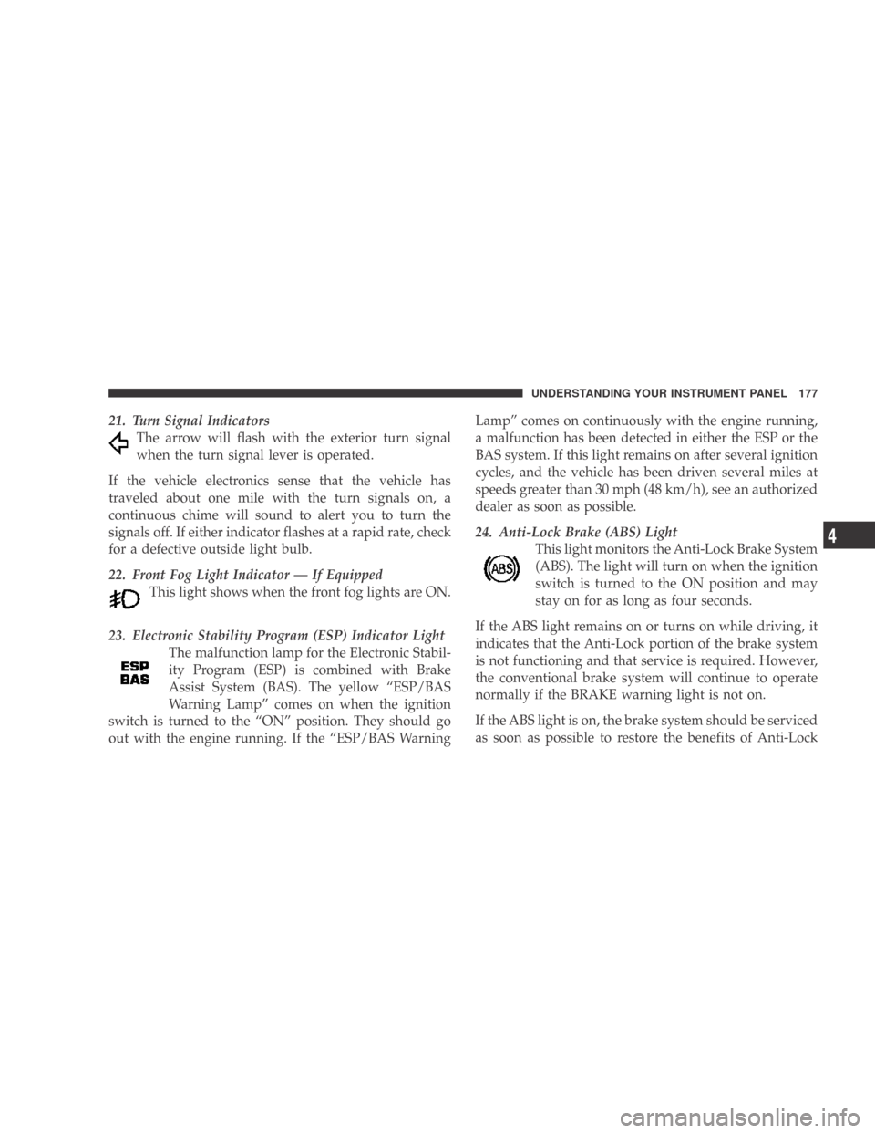
21. Turn Signal IndicatorsThe arrow will flash with the exterior turn signal
when the turn signal lever is operated.
If the vehicle electronics sense that the vehicle has
traveled about one mile with the turn signals on, a
continuous chime will sound to alert you to turn the
signals off. If either indicator flashes at a rapid rate, check
for a defective outside light bulb.
22. Front Fog Light Indicator — If Equipped This light shows when the front fog lights are ON.
23. Electronic Stability Program (ESP) Indicator Light The malfunction lamp for the Electronic Stabil-
ity Program (ESP) is combined with Brake
Assist System (BAS). The yellow “ESP/BAS
Warning Lamp” comes on when the ignition
switch is turned to the “ON” position. They should go
out with the engine running. If the “ESP/BAS Warning Lamp” comes on continuously with the engine running,
a malfunction has been detected in either the ESP or the
BAS system. If this light remains on after several ignition
cycles, and the vehicle has been driven several miles at
speeds greater than 30 mph (48 km/h), see an authorized
dealer as soon as possible.
24. Anti-Lock Brake (ABS) Light
This light monitors the Anti-Lock Brake System
(ABS). The light will turn on when the ignition
switch is turned to the ON position and may
stay on for as long as four seconds.
If the ABS light remains on or turns on while driving, it
indicates that the Anti-Lock portion of the brake system
is not functioning and that service is required. However,
the conventional brake system will continue to operate
normally if the BRAKE warning light is not on.
If the ABS light is on, the brake system should be serviced
as soon as possible to restore the benefits of Anti-Lock
UNDERSTANDING YOUR INSTRUMENT PANEL 177
4
Page 180 of 431
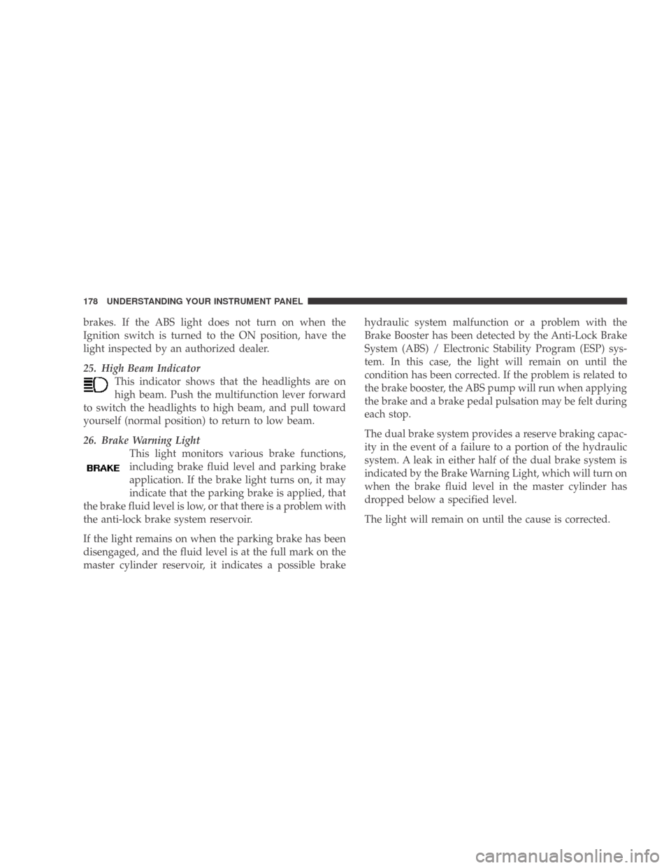
brakes. If the ABS light does not turn on when the
Ignition switch is turned to the ON position, have the
light inspected by an authorized dealer.
25. High Beam IndicatorThis indicator shows that the headlights are on
high beam. Push the multifunction lever forward
to switch the headlights to high beam, and pull toward
yourself (normal position) to return to low beam.
26. Brake Warning Light This light monitors various brake functions,
including brake fluid level and parking brake
application. If the brake light turns on, it may
indicate that the parking brake is applied, that
the brake fluid level is low, or that there is a problem with
the anti-lock brake system reservoir.
If the light remains on when the parking brake has been
disengaged, and the fluid level is at the full mark on the
master cylinder reservoir, it indicates a possible brake hydraulic system malfunction or a problem with the
Brake Booster has been detected by the Anti-Lock Brake
System (ABS) / Electronic Stability Program (ESP) sys-
tem. In this case, the light will remain on until the
condition has been corrected. If the problem is related to
the brake booster, the ABS pump will run when applying
the brake and a brake pedal pulsation may be felt during
each stop.
The dual brake system provides a reserve braking capac-
ity in the event of a failure to a portion of the hydraulic
system. A leak in either half of the dual brake system is
indicated by the Brake Warning Light, which will turn on
when the brake fluid level in the master cylinder has
dropped below a specified level.
The light will remain on until the cause is corrected.
178 UNDERSTANDING YOUR INSTRUMENT PANEL