tow DODGE CALIBER 2012 1.G Owner's Manual
[x] Cancel search | Manufacturer: DODGE, Model Year: 2012, Model line: CALIBER, Model: DODGE CALIBER 2012 1.GPages: 100, PDF Size: 2.63 MB
Page 64 of 100
IF YOUR ENGINE OVERHEATS
• In any of the following situations, you can reduce the potential for overheating bytaking the appropriate action.
• On the highways — slow down.
• In city traffic — while stopped, place the transmission in NEUTRAL, but do not increase engine idle speed.
NOTE: There are steps that you can take to slow down an impending overheat
condition:
• If your air conditioner (A/C) is on, turn it off. The A/C system adds heat to the engine cooling system and turning the A/C off can help remove this heat.
• You can also turn the temperature control to maximum heat, the mode control to floor and the blower control to high. This allows the heater core to act as a
supplement to the radiator and aids in removing heat from the engine cooling
system.
CAUTION!
Driving with a hot cooling system could damage your vehicle. If the temperature
gauge reads 240°F (116 °C) or greater pull over and stop the vehicle. Idle the
vehicle with the air conditioner turned off until the pointer drops back into the
normal range 200–230°F (93–110°C). If the pointer remains at 240°F (116°C)
or greater and you hear a chime, turn the engine off immediately and call for
service.
WARNING!
You or others can be badly burned by hot engine coolant (antifreeze) or steam
from your radiator. If you see or hear steam coming from under the hood, do not
open the hood until the radiator has had time to cool. Never try to open a
cooling system pressure cap when the radiator or coolant bottle is hot.
AUTOMATIC TRANSMISSION OVERHEATING
• During sustained high speed driving or trailer towing up long grades on hot days,the automatic transmission oil may become too hot.
• When the transmission overheat warning light
turns on, you will experience
reduced performance until the automatic transmission cools down. Once the
transmission has cooled down and the light turns off, you may continue to drive
normally. If the high speed is maintained, the overheating will continue to occur.
• If the overheating continues, it may become necessary to stop the vehicle and run the engine at idle with the transmission in NEUTRAL until the light turns off.
WHAT TO DO IN EMERGENCIES
62
Page 65 of 100
JACKING AND TIRE CHANGING
Jack Location
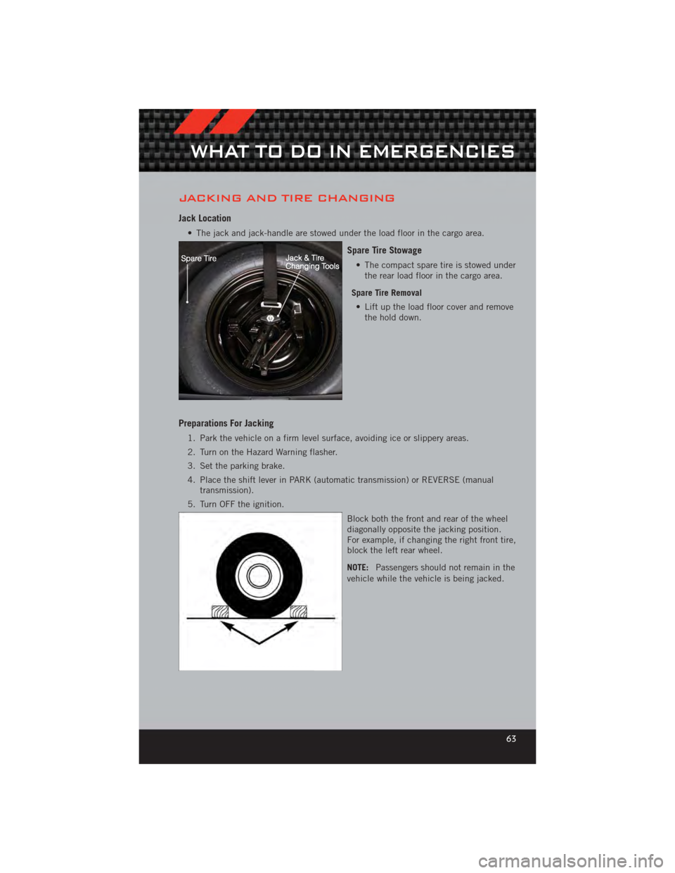
• The jack and jack-handle are stowed under the load floor in the cargo area.
Spare Tire Stowage
• The compact spare tire is stowed underthe rear load floor in the cargo area.
Spare Tire Removal • Lift up the load floor cover and remove the hold down.
Preparations For Jacking
1. Park the vehicle on a firm level surface, avoiding ice or slippery areas.
2. Turn on the Hazard Warning flasher.
3. Set the parking brake.
4. Place the shift lever in PARK (automatic transmission) or REVERSE (manual transmission).
5. Turn OFF the ignition.
Block both the front and rear of the wheel
diagonally opposite the jacking position.
For example, if changing the right front tire,
block the left rear wheel.
NOTE:Passengers should not remain in the
vehicle while the vehicle is being jacked.
WHAT TO DO IN EMERGENCIES
63
Page 67 of 100
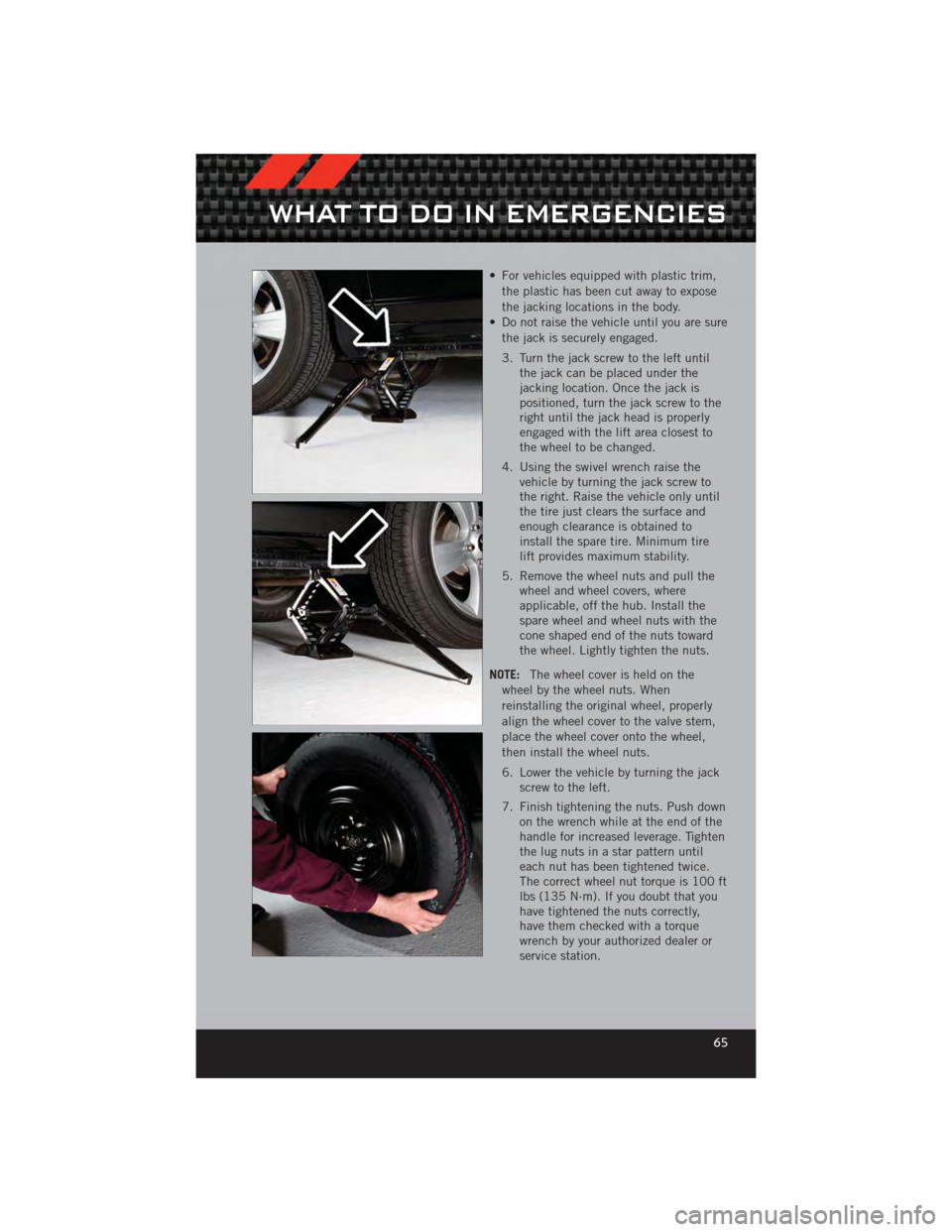
• For vehicles equipped with plastic trim,the plastic has been cut away to expose
the jacking locations in the body.
• Do not raise the vehicle until you are sure the jack is securely engaged.
3. Turn the jack screw to the left until the jack can be placed under the
jacking location. Once the jack is
positioned, turn the jack screw to the
right until the jack head is properly
engaged with the lift area closest to
the wheel to be changed.
4. Using the swivel wrench raise the vehicle by turning the jack screw to
the right. Raise the vehicle only until
the tire just clears the surface and
enough clearance is obtained to
install the spare tire. Minimum tire
lift provides maximum stability.
5. Remove the wheel nuts and pull the wheel and wheel covers, where
applicable, off the hub. Install the
spare wheel and wheel nuts with the
cone shaped end of the nuts toward
the wheel. Lightly tighten the nuts.
NOTE: The wheel cover is held on the
wheel by the wheel nuts. When
reinstalling the original wheel, properly
align the wheel cover to the valve stem,
place the wheel cover onto the wheel,
then install the wheel nuts.
6. Lower the vehicle by turning the jack screw to the left.
7. Finish tightening the nuts. Push down on the wrench while at the end of the
handle for increased leverage. Tighten
the lug nuts in a star pattern until
each nut has been tightened twice.
The correct wheel nut torque is 100 ft
lbs (135 N·m). If you doubt that you
have tightened the nuts correctly,
have them checked with a torque
wrench by your authorized dealer or
service station.
WHAT TO DO IN EMERGENCIES
65
Page 68 of 100
8. Remove the wheel blocks and lower the jack until it is free. Reassemble the lugwrench to the jack assembly and stow it in the spare tire area. Secure the
assembly using the means provided.
9. Place the deflated (flat) tire in the cargo area, have the tire repaired or replaced as
soon as possible.
10. Check the spare tire pressure as soon as possible. Correct the tire pressure as required.
Road Tire Installation
Vehicles Equipped With Wheel Covers
1. Mount the road tire on the axle.
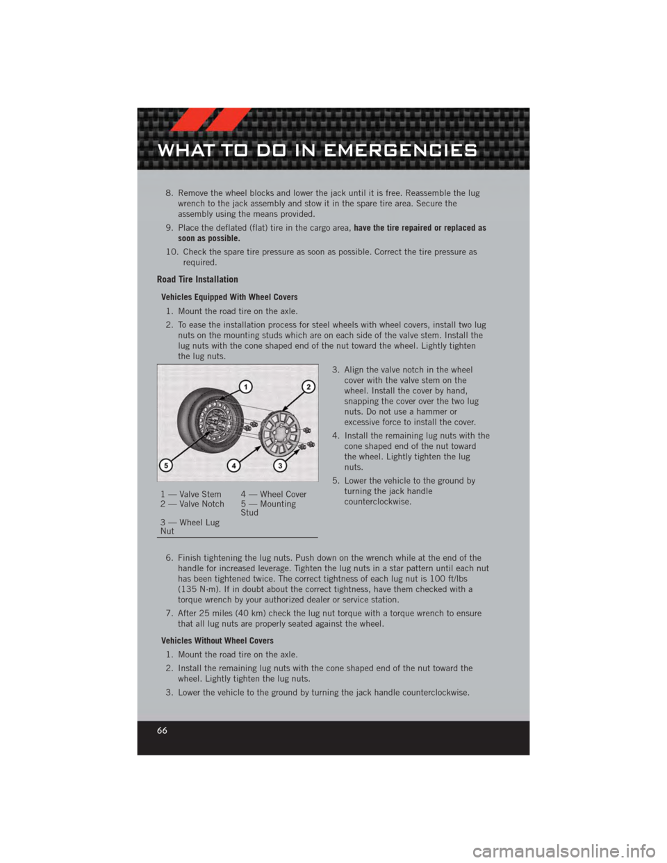
2. To ease the installation process for steel wheels with wheel covers, install two lug nuts on the mounting studs which are on each side of the valve stem. Install the
lug nuts with the cone shaped end of the nut toward the wheel. Lightly tighten
the lug nuts.
3. Align the valve notch in the wheelcover with the valve stem on the
wheel. Install the cover by hand,
snapping the cover over the two lug
nuts. Do not use a hammer or
excessive force to install the cover.
4. Install the remaining lug nuts with the cone shaped end of the nut toward
the wheel. Lightly tighten the lug
nuts.
5. Lower the vehicle to the ground by turning the jack handle
counterclockwise.
6. Finish tightening the lug nuts. Push down on the wrench while at the end of the handle for increased leverage. Tighten the lug nuts in a star pattern until each nut
has been tightened twice. The correct tightness of each lug nut is 100 ft/lbs
(135 N·m). If in doubt about the correct tightness, have them checked with a
torque wrench by your authorized dealer or service station.
7. After 25 miles (40 km) check the lug nut torque with a torque wrench to ensure that all lug nuts are properly seated against the wheel.
Vehicles Without Wheel Covers 1. Mount the road tire on the axle.
2. Install the remaining lug nuts with the cone shaped end of the nut toward the wheel. Lightly tighten the lug nuts.
3. Lower the vehicle to the ground by turning the jack handle counterclockwise.
1 — Valve Stem 4 — Wheel Cover
2 — Valve Notch 5 — Mounting Stud
3 — Wheel Lug
Nut
WHAT TO DO IN EMERGENCIES
66
Page 70 of 100
WARNING!(Continued)
• To assure that spare tires, flat or inflated, are securely stowed, sparesmust be stowed with the valve stem facing the ground.
• Raising the vehicle higher than necessary can make the vehicle less stable. It could slip off the jack and hurt someone near it. Raise the vehicle only
enough to remove the tire.
• To avoid possible personal injury, handle the wheel covers with care to avoid contact with any sharp edges.
• A loose tire or jack thrown forward in a collision or hard stop could injure the occupants in the vehicle. Have the deflated (flat) tire repaired or replaced
immediately.
• To avoid the risk of forcing the vehicle off the jack, do not tighten the lug nuts fully until the vehicle is lowered to the ground. Failure to follow this
warning may result in personal injury.
JUMP-STARTING PROCEDURES
• If your vehicle has a discharged battery it can be jump-started using a set ofjumper cables and a battery in another vehicle or by using a portable battery
booster pack. Jump-starting can be dangerous if done improperly so please follow
the procedures in this section carefully.
NOTE: When using a portable battery booster pack follow the manufacturer’s operating
instructions and precautions.
Preparations For Jump-Start
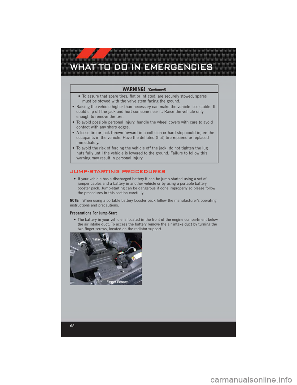
• The battery in your vehicle is located in the front of the engine compartment below the air intake duct. To access the battery remove the air intake duct by turning the
two finger screws, located on the radiator support.
WHAT TO DO IN EMERGENCIES
68
Page 74 of 100
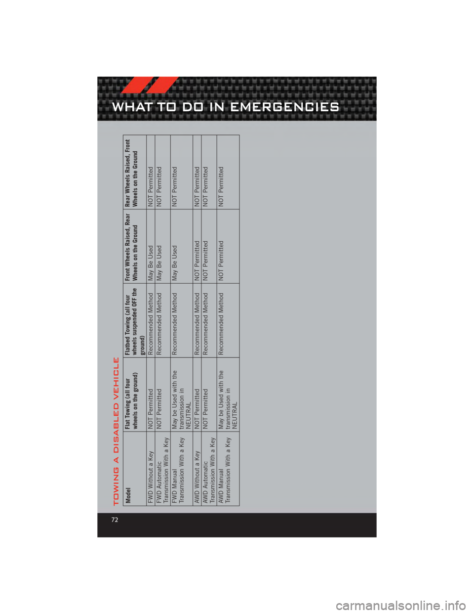
TOWING A DISABLED VEHICLEModelFlat Towing (all four
wheels on the ground)Flatbed Towing (all four
wheels suspended OFF the
ground)Front Wheels Raised, Rear
Wheels on the Ground
Rear Wheels Raised, Front
Wheels on the Ground
FWD Without a Key NOT Permitted Recommended Method May Be UsedNOT Permitted
FWD Automatic
Transmission With a Key NOT Permitted
Recommended Method May Be Used NOT Permitted
FWD Manual
Transmission With a Key May be Used with the
transmission in
NEUTRALRecommended Method May Be Used
NOT Permitted
AWD Without a Key NOT Permitted Recommended Method NOT PermittedNOT Permitted
AWD Automatic
Transmission With a Key NOT Permitted
Recommended Method NOT Permitted NOT Permitted
AWD Manual
Transmission With a Key May be Used with the
transmission in
NEUTRALRecommended Method NOT Permitted
NOT Permitted
WHAT TO DO IN EMERGENCIES
72
Page 81 of 100
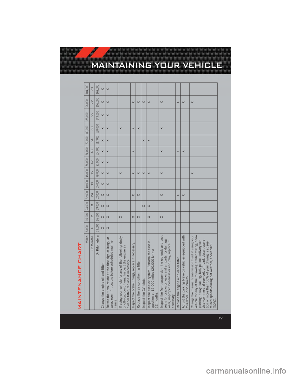
MAINTENANCE CHART
Miles:
8,000 16,000 24,000 32,000 40,000 48,000 56,000 64,000 72,000 80,000 88,000 96,000 104,000
Or Months: 6 12 18 24 30 36 42 48 54 60 66 72 78
Or Kilometers:
13,000 26,000 39,000 52,000 65,000 78,000 91,000
104,000
117,000
130,000 143,000 156,000 169,000
Change the engine oil and filter. X XXXXXXXX X X X X
Rotate the tires, rotate at the first sign of irregular
wear, even if it occurs before scheduled mainte-
nance. XXXXXXXXX X X X X
If using your vehicle for any of the following: dusty
or off-road conditions. Inspect the engine air
cleaner filter; replace if necessary. XX X
Inspect the brake linings; replace if necessary. XXXX X X
Replace the air conditioning filter. XXX XX
Inspect the CV joints. XXX X
Inspect the exhaust system. Perform the first in-
spection at 12,000 miles (20,000 km) or
12 months. X
XXX X
Inspect the front suspension, tie rod ends and boot
seals for cracks or leaks and all parts for damage,
wear, improper looseness or end play; replace if
necessary. XXXX X X
Replace the engine air cleaner filter. XX X
Adjust the parking brake on vehicles equipped with
four-wheel disc brakes. XX X
Change the manual transmission fluid if using your
vehicle for any of the following: trailer towing, snow
plowing, heavy loading, taxi, police, delivery ser-
vice (commercial service), off road, desert opera-
tion or more than 50% of your driving is at sus-
tained speeds during hot weather, above 90°F
(32°C). XX
MAINTAINING YOUR VEHICLE
79
Page 82 of 100
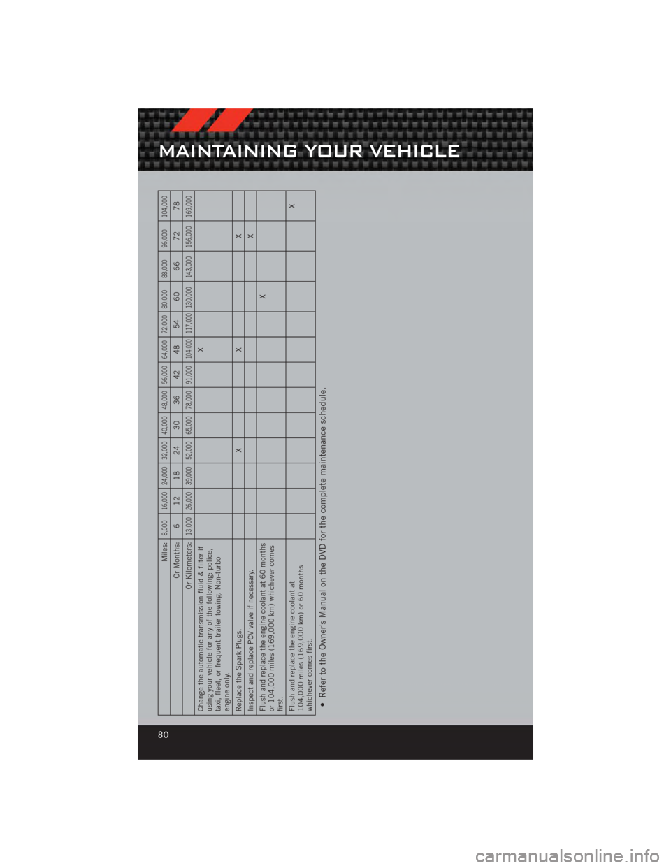
Miles:
8,000 16,000 24,000 32,000 40,000 48,000 56,000 64,000 72,000 80,000 88,000 96,000 104,000
Or Months: 6 12 18 24 30 36 42 48 54 60 66 72 78
Or Kilometers:
13,000 26,000 39,000 52,000 65,000 78,000 91,000
104,000
117,000
130,000 143,000 156,000 169,000
Change the automatic transmission fluid & filter if
using your vehicle for any of the following: police,
taxi, fleet, or frequent trailer towing. Non-turbo
engine only. X
Replace the Spark Plugs. X X X
Inspect and replace PCV valve if necessary. X
Flush and replace the engine coolant at 60 months
or 104,000 miles (169,000 km) whichever comes
first. X
Flush and replace the engine coolant at
104,000 miles (169,000 km) or 60 months
whichever comes first. X• Refer to the Owner's Manual on the DVD for the complete maintenance schedule.
MAINTAINING YOUR VEHICLE
80
Page 84 of 100
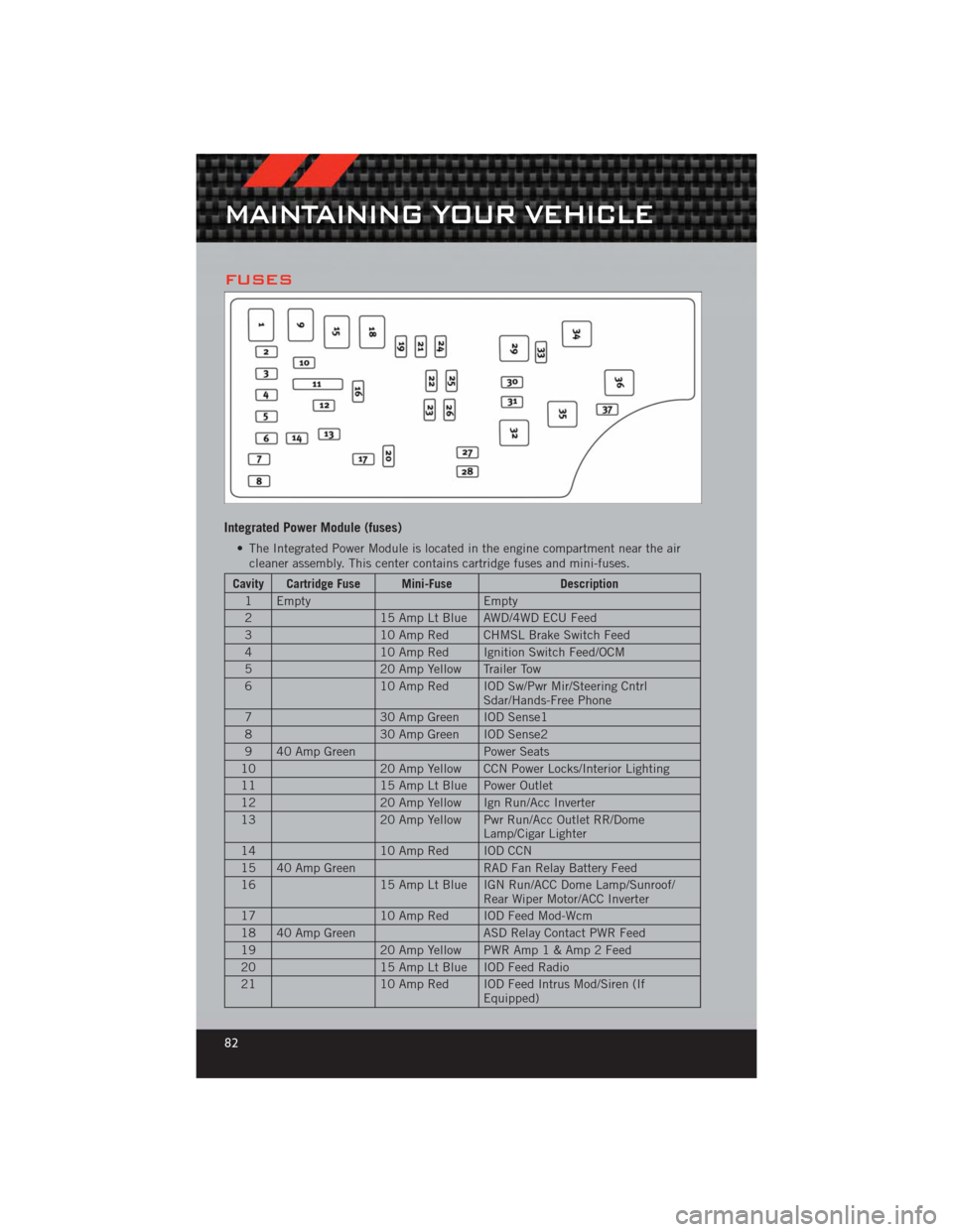
FUSES
Integrated Power Module (fuses)
• The Integrated Power Module is located in the engine compartment near the aircleaner assembly. This center contains cartridge fuses and mini-fuses.
Cavity Cartridge Fuse Mini-Fuse Description
1 Empty Empty
2 15 Amp Lt Blue AWD/4WD ECU Feed
3 10 Amp Red CHMSL Brake Switch Feed
4 10 Amp Red Ignition Switch Feed/OCM
5 20 Amp Yellow Trailer Tow
6 10 Amp Red IOD Sw/Pwr Mir/Steering Cntrl
Sdar/Hands-Free Phone
7 30 Amp Green IOD Sense1
8 30 Amp Green IOD Sense2
9 40 Amp Green Power Seats
10 20 Amp Yellow CCN Power Locks/Interior Lighting
11 15 Amp Lt Blue Power Outlet
12 20 Amp Yellow Ign Run/Acc Inverter
13 20 Amp Yellow Pwr Run/Acc Outlet RR/Dome
Lamp/Cigar Lighter
14 10 Amp Red IOD CCN
15 40 Amp Green RAD Fan Relay Battery Feed
16 15 Amp Lt Blue IGN Run/ACC Dome Lamp/Sunroof/
Rear Wiper Motor/ACC Inverter
17 10 Amp Red IOD Feed Mod-Wcm
18 40 Amp Green ASD Relay Contact PWR Feed
19 20 Amp Yellow PWR Am p1&Amp2Feed
20 15 Amp Lt Blue IOD Feed Radio
21 10 Amp Red IOD Feed Intrus Mod/Siren (If
Equipped)
MAINTAINING YOUR VEHICLE
82
Page 91 of 100
Heated Mirrors........... 21,22
Heated Seats .............. 15
High Beam/Low Beam Select
(Dimmer) Switch ............ 18
HomeLink
®(Garage Door Opener)
Transmitter ............... 52
Hood Release .............. 75
Instrument Cluster ............ 6
Indicators ............... 7
Instrument Cluster Warning
Lights ................. 6,58
Integrated Power Module (Fuses) . . . 82
Intermittent Wipers (Delay Wipers) . . 18
Introduction ............... 2
Inverter Outlet (115V) ......... 54
Inverter, Power ............. 54
iPod
®/USB/MP3 Control ........ 45
Bluetooth Streaming Audio ..... 50
Jack Location .............. 63
Jack Operation ........... 63,64
Jacking Instructions .......... 64
Jump Starting .............. 68
KeyFob .................. 8
Key Fob Programmable Features . . . 51
Lane Change Assist .......... 18
LATCH (Lower Anchors and Tether
forCHildren) .............. 11
Lights Headlights .............. 17
Park .................. 17
Transmission Warning ........ 61
TurnSignal .............. 18
Warning (Instrument Cluster
Description) .............. 6
Maintenance Record .......... 81
MaintenanceSchedule ........ 79
Malfunction Indicator Light
(CheckEngine) ............. 60
MediaCenterRadio ...... 26,28,30
Mirrors Heated .............. 21,22 MOPAR
®Accessories
......... 87
Navigation ................ 39
New Vehicle Break-In Period ..... 17
Oil Change Indicator .......... 61
Oil Change Indicator, Reset ...... 61
Oil Pressure Light ........... 60
Oil, Engine Capacity ............... 78
Outlet Power ................. 55
Overheating, Engine .......... 62
Panic Alarm ............... 8
Phone (Pairing) ............. 46
Phone (Uconnect) ........... 46
Placard, Tire and Loading
Information ............... 83
Power Glass Sunroof ............ 22
Inverter ................ 54
Outlet
(Auxiliary Electrical Outlet) ..... 55
Seats ................. 13
Steering ................ 78
Preparation for Jacking ........ 63
Programmable Electronic Features . . 51
Radio Operation ............ 33
Rain Sensitive Wiper System ..... 18
Rear Seat, Folding ........... 15
Recreational Towing .......... 57
Remote Starting System ........ 8
ReplacementBulbs .......... 84
Reporting Safety Defects ....... 86
Restraints, Child ............ 11
Seat Belts ................. 9
Seats ................... 13
Adjustment .............. 13
Folding Front Passenger ...... 14
Heated ................ 15
Power ................. 13
RearFolding ............. 15
Seek Button ...... 26,27,29,31,32
Setting the Clock ...... 26,28,31,33
INDEX
89