turn signal DODGE CARAVAN 2008 5.G Owner's Manual
[x] Cancel search | Manufacturer: DODGE, Model Year: 2008, Model line: CARAVAN, Model: DODGE CARAVAN 2008 5.GPages: 531, PDF Size: 7.72 MB
Page 374 of 531
The Basic TPMS consists of the following components:
²Receiver Module
²Four Wheel Sensors
²TPMS Telltale Warning Light
The TPMS Telltale Warning Light will illumi-
nate in the instrument cluster, and an audible
chime will be activated when one or more of
the four active road tire pressures are low.
Should this occur, you should stop as soon as possible,
check the inflation pressure of each tire on your vehicle,
and inflate each tire to the vehicle's recommended cold
tire pressure value (located on the placard on the
driver's-side B-Pillar). The system will automatically
update and the TPMS Warning Lamp will extinguish
once the updated tire pressures have been received.
NOTE:
The vehicle may need to be driven for up to 10
minutes above 15 mph (25 km/h) to receive this information.
The TPMS Warning Lamp will flash on and off for 75
seconds, and remain on sold when a system fault is
detected. The system fault will also sound a chime. If the
ignition key is cycled, this sequence will repeat, provid-
ing the system fault still exists. The TPMS Warning Lamp
will turn off when the fault condition no longer exists. A
system fault can occur with any of the following sce-
narios:
1. Jamming due to electronic devices or driving next to
facilities emitting the same radio frequencies as the TPMS
sensors.
2. Installing some form of aftermarket window tinting
that affects radio wave signals.
3. Accumulation of excessive snow and/or ice around
the wheels or wheel housings.
4. Using tire chains on the vehicle.
5. Using wheels/tires not equipped with TPMS sensors.
372 STARTING AND OPERATING
Page 406 of 531
Towing Requirements Ð Trailer Lights and Wiring
Whenever you pull a trailer, regardless of the trailer size,
stop lights and turn signals on the trailer are required for
motoring safety.
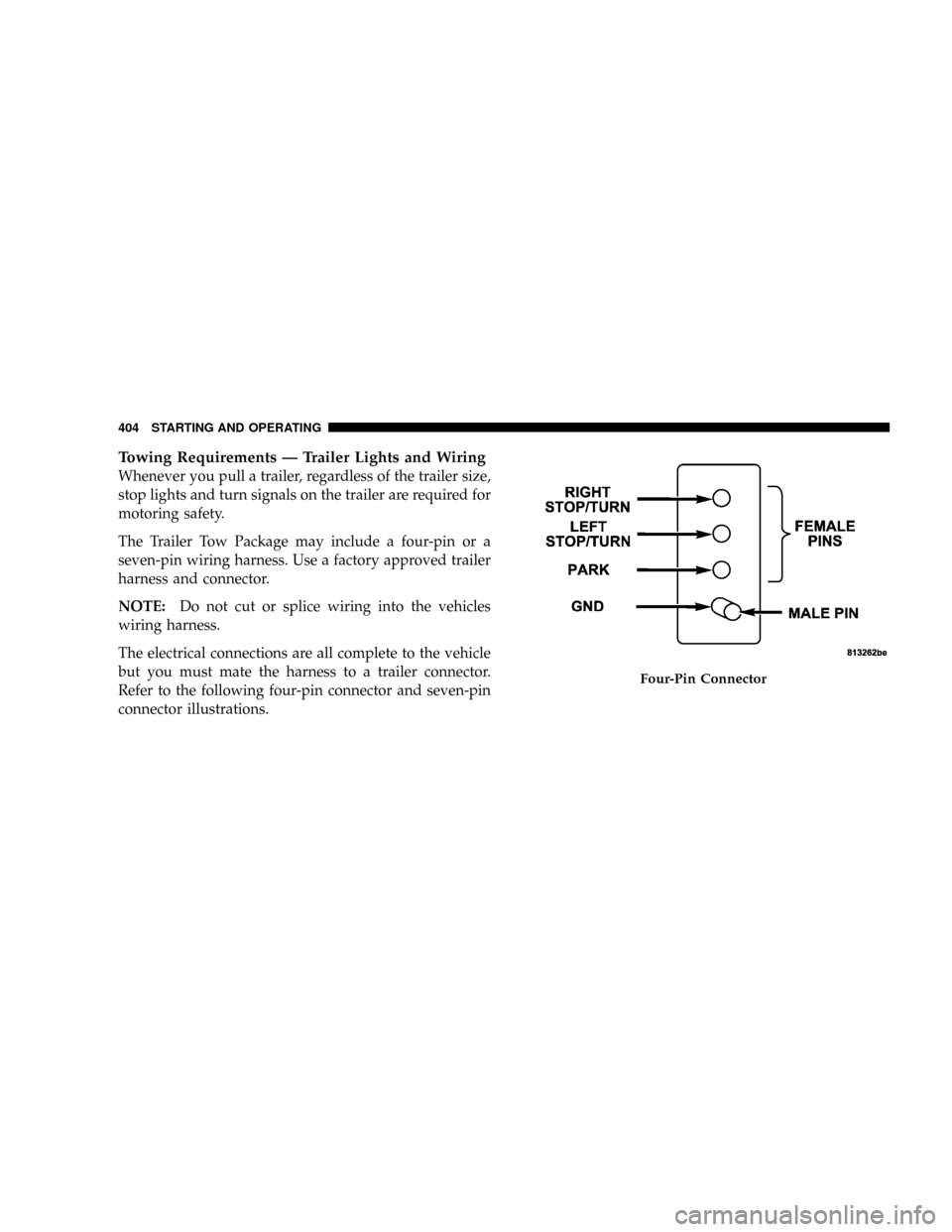
The Trailer Tow Package may include a four-pin or a
seven-pin wiring harness. Use a factory approved trailer
harness and connector.
NOTE:Do not cut or splice wiring into the vehicles
wiring harness.
The electrical connections are all complete to the vehicle
but you must mate the harness to a trailer connector.
Refer to the following four-pin connector and seven-pin
connector illustrations.
Four-Pin Connector
404 STARTING AND OPERATING
Page 412 of 531
HAZARD WARNING FLASHER
The hazard flasher switch is located in the center of
the instrument panel below the radio.
To engage the Hazard Warning Flashers, depress the
switch on the instrument panel. When the Hazard Warn-
ing Switch is activated, all directional turn signals will
flash on and off to warn oncoming traffic of an emer-
gency. Push the switch a second time to turn off the
flashers.
This is an emergency warning system and should not be
used when the vehicle is in motion. Use it when your
vehicle is disabled and is creating a safety hazard for
other motorists.
When you must leave the vehicle to seek assistance, the
Hazard Warning Flashers will continue to operate even
though the ignition switch is OFF.NOTE:With extended use, the Hazard Warning Flash-
ers may wear down your battery.
IF YOUR ENGINE OVERHEATS
In any of the following situations, you can reduce the
potential for overheating by taking the appropriate ac-
tion.
²On the highways Ð Slow down.
²In city traffic Ð While stopped, shift the transmission
gear selector lever into NEUTRAL, but do not increase
engine idle speed.
NOTE:There are steps that you can take to slow down
an impending overheat condition. If your air conditioner
is on, turn it off. The air conditioning system adds heat to
the engine cooling system and turning off the A/C
removes this heat. You can also turn the Temperature
control to maximum heat, the Mode control to floor, and
410 WHAT TO DO IN EMERGENCIES
Page 434 of 531
NPower Steering Ð Fluid Check............452
NFront Suspension Ð Ball Joints............453
NSteering Shaft Seal....................453
NDrive Shaft Universal Joints..............454
NBody Lubrication.....................454
NWindshield Wiper Blades................454
NCooling System.......................456
NHoses And Vacuum/Vapor Harnesses.......461
NFuel System Connections................461
NBrakes.............................462
NAutomatic Transaxle...................464
NFront And Rear Wheel Bearings...........467NAppearance Care And Protection From
Corrosion...........................467
NCleaning The Instrument Panel Cup Holders . . 473
mFuses/Totally Integrated Power Module
(TIPM)..............................474
mVehicle Storage........................481
mReplacement Light Bulbs.................481
mBulb Replacement......................482
NHeadlights..........................482
NFront Park/Turn Signal And Side Marker
Lights.............................483
NFog Lights..........................483
NRear Tail, Stop, Turn Signal, Side Marker And
Backup Lights........................484
432 MAINTAINING YOUR VEHICLE
Page 484 of 531
NOTE:For lighted switches, see your dealer for replace-
ment.
All of the interior bulbs are glass wedge base or glass
cartridge types. Aluminum base bulbs are not approved
and should not be used for replacement.
LIGHT BULBS Ð Exterior Bulb Number
Backup, Tail, Stop Light...................3157
Center High-Mounted Stop Light. . . LED (See Note 1)
Fog Light Ð If Equipped..................9145
Front Side Marker,
Park/Turn Signal............... P27/7Wor3157
Headlight............................. H13
License................................ 168
Note 1: The Center High-Mounted Stop Light (CHMSL)
uses LED lights that are not serviceable separately. The
CHMSL must be replaced as an assembly, see your
authorized Dealer.BULB REPLACEMENT
Headlights
1.Raise the hood to access the rear of the headlight housing.
2. Slide the red lock tab rearward on the connector, then
depress the tab and remove the connector from the bulb.
3. Twist the headlight bulb and pull the bulb from
headlight housing.
4. Install the new headlight bulb and twist until locked
into the headlight housing.
CAUTION!
Do not touch the new bulb with your fingers. Oil
contamination will severely shorten bulb life. If the
bulb comes in contact with an oily surface, clean the
bulb with rubbing alcohol.
482 MAINTAINING YOUR VEHICLE
Page 485 of 531
5. Connect the wiring connector to bulb and slide red
lock tab forward.
Front Park/Turn Signal and Side Marker Lights
1. Raise the hood to access the rear of the headlight
housing.
2. Twist the turn signal socket and remove from the
headlight housing, then pull the bulb out.
3. Push the new bulb into the socket and reinstall the
socket by twisting until locked into the headlight hous-
ing.
Fog Lights
NOTE:Access to the fog light bulb is from the rear of
the fascia. On the left rear side of the fascia, remove the
push pin and lower the hinged access door on the air
dam.1. From behind the bumper fascia, or the access panel on
the air dam, twist the bulb counterclockwise, and remove
bulb.
CAUTION!
Do not touch the new bulb with your fingers. Oil
contamination will severely shorten bulb life. If the
bulb comes in contact with an oily surface, clean the
bulb with rubbing alcohol.
2. Disconnect wire harness from the bulb.
3. Reconnect the wiring harness to the new bulb and
reinstall the bulb by twisting clockwise.
MAINTAINING YOUR VEHICLE 483
7
Page 486 of 531
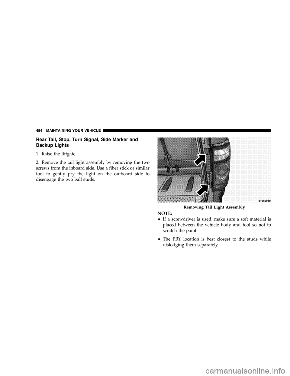
Rear Tail, Stop, Turn Signal, Side Marker and
Backup Lights
1. Raise the liftgate.
2. Remove the tail light assembly by removing the two
screws from the inboard side. Use a fiber stick or similar
tool to gently pry the light on the outboard side to
disengage the two ball studs.
NOTE:
²If a screwdriver is used, make sure a soft material is
placed between the vehicle body and tool so not to
scratch the paint.
²The PRY location is best closest to the studs while
dislodging them separately.
Removing Tail Light Assembly
484 MAINTAINING YOUR VEHICLE
Page 487 of 531
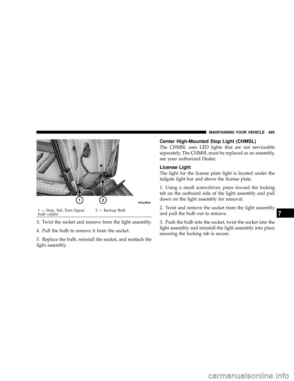
3. Twist the socket and remove form the light assembly.
4. Pull the bulb to remove it from the socket.
5. Replace the bulb, reinstall the socket, and reattach the
light assembly.
Center High-Mounted Stop Light (CHMSL)
The CHMSL uses LED lights that are not serviceable
separately. The CHMSL must be replaced as an assembly,
see your authorized Dealer.
License Light
The light for the license plate light is located under the
tailgate light bar and above the license plate.
1. Using a small screwdriver, press inward the locking
tab on the outboard side of the light assembly and pull
down on the light assembly for removal.
2. Twist and remove the socket from the light assembly
and pull the bulb out to remove.
3. Push the bulb into the socket, twist the socket into the
light assembly and reinstall the light assembly into place
ensuring the locking tab is secure.
1 Ð Stop, Tail, Turn Signal
bulb combo2 Ð Backup BulbMAINTAINING YOUR VEHICLE 4857
Page 516 of 531

Flashers
Hazard Warning....................... 410
Turn Signal.....................227,483,484
Flash-To-Pass........................... 170
Flat Tire Stowage........................ 422
Flexible Fuel Vehicles
Cruising Range........................ 387
Engine Oil........................... 387
Fuel Requirements..................384,386
Maintenance.......................... 388
Replacement Parts..................... 387
Starting............................. 387
Flooded Engine Starting................... 326
Floor Console.......................... 201
Fluid Capacities......................... 486
Fluid Leaks............................. 94
Fluid Level Checks
Automatic Transaxle.................... 465
Automatic Transmission................. 466Brake............................... 463
Power Steering........................ 452
Fluids................................ 487
Fluids, Lubricants and Genuine Parts.......... 487
Fog Light Service........................ 483
Fog Lights.......................165,233,483
Fold in Floor (Stow8n Go) Seating........... 138
Freeing A Stuck Vehicle................... 427
Fuel................................. 377
Adding............................. 382
Additives............................ 380
Clean Air............................ 378
Filler Cap (Gas Cap).................226,382
Filler Door (Gas Cap)................... 226
Gasoline............................ 377
Gauge.............................. 226
Hoses.............................. 461
Light............................... 234
Octane Rating........................ 487
514 INDEX
Page 520 of 531

License............................. 485
Lights On Reminder.................... 165
Low Fuel............................ 234
Malfunction Indicator (Check Engine)........ 232
Oil Pressure.......................... 233
Park.............................162,483
Passing............................. 170
Reading............................. 183
Rear Servicing........................ 484
Rear Tail............................ 484
Seat Belt Reminder..................... 233
Security Alarm (Theft Alarm).............. 233
Service...........................481,482
Service Engine Soon (Malfunction Indicator) . . . 232
Side Marker.......................... 484
Theft Alarm (Security Alarm).............. 233
Turn Signal.....................166,483,484
Voltage............................. 234
Warning (Instrument Cluster Description)..... 226Load Leveling System.................... 218
Loading Vehicle...................214,388,391
Capacities........................... 391
Tires ............................... 353
Locks
Door................................ 31
Lower Anchors and Tether for CHildren (LATCH)... 86
Lubrication, Body....................... 454
Luggage Rack (Roof Rack)................. 215
Lumbar Support........................ 137
Maintenance Free Battery.................. 448
Maintenance Procedures................... 441
Maintenance Schedule.................... 490
Maintenance, Sunroof..................... 195
Malfunction Indicator Light (Check Engine) . . 232,438
Manual, Service......................... 504
Map/Reading Lights..................... 183
Memory Feature (Memory Seat)............. 155
518 INDEX