DODGE CARAVAN 2012 Owners Manual
Manufacturer: DODGE, Model Year: 2012, Model line: CARAVAN, Model: DODGE CARAVAN 2012Pages: 643, PDF Size: 11.83 MB
Page 581 of 643
FUSES
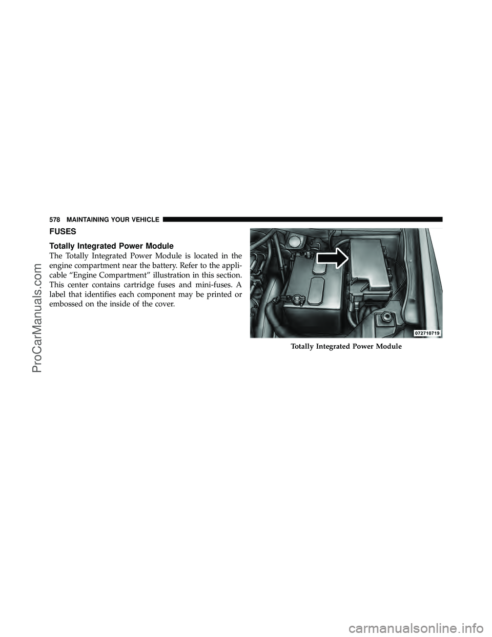
Totally Integrated Power Module
The Totally Integrated Power Module is located in the
engine compartment near the battery. Refer to the appli-
cable “Engine Compartment” illustration in this section.
This center contains cartridge fuses and mini-fuses. A
label that identifies each component may be printed or
embossed on the inside of the cover.
Totally Integrated Power Module
578 MAINTAINING YOUR VEHICLE
ProCarManuals.com
Page 582 of 643
CAUTION!
•When installing the Totally Integrated Power
Module cover, it is important to ensure the cover is
properly positioned and fully latched. Failure to
do so may allow water to get into the Integrated
Power Module, and possibly result in a electrical
system failure.
•When replacing a blown fuse, it is important to
use only a fuse having the correct amperage rating.
The use of a fuse with a rating other than indicated
may result in a dangerous electrical system over-
load. If a properly rated fuse continues to blow, it
indicates a problem in the circuit that must be
corrected.
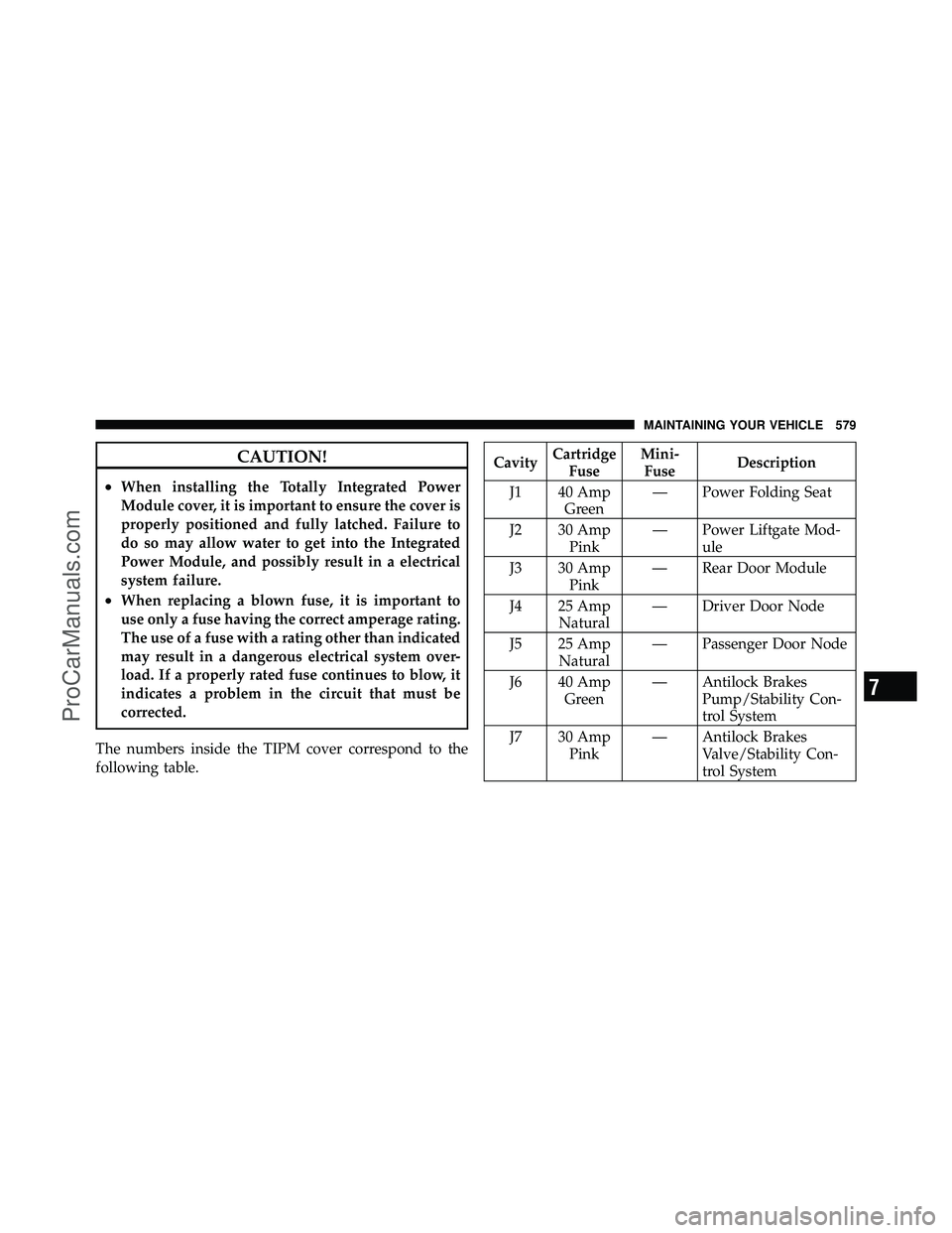
The numbers inside the TIPM cover correspond to the
following table.
Cavity Cartridge
Fuse Mini-
Fuse Description
J1 40 Amp Green — Power Folding Seat
J2 30 Amp Pink — Power Liftgate Mod-
ule
J3 30 Amp Pink — Rear Door Module
J4 25 Amp Natural — Driver Door Node
J5 25 Amp Natural — Passenger Door Node
J6 40 Amp Green — Antilock Brakes
Pump/Stability Con-
trol System
J7 30 Amp Pink — Antilock Brakes
Valve/Stability Con-
trol System
7
MAINTAINING YOUR VEHICLE 579
ProCarManuals.com
Page 583 of 643
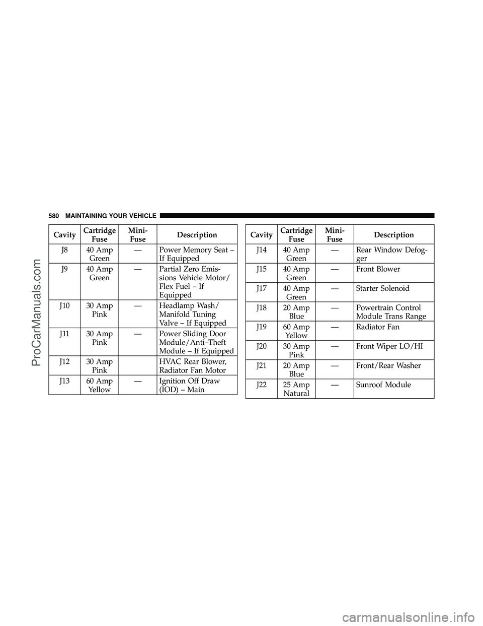
CavityCartridge
Fuse Mini-
Fuse Description
J8 40 Amp Green — Power Memory Seat –
If Equipped
J9 40 Amp Green — Partial Zero Emis-
sions Vehicle Motor/
Flex Fuel – If
Equipped
J10 30 Amp Pink — Headlamp Wash/
Manifold Tuning
Valve – If Equipped
J11 30 Amp Pink — Power Sliding Door
Module/Anti–Theft
Module – If Equipped
J12 30 Amp Pink HVAC Rear Blower,
Radiator Fan Motor
J13 60 Amp Yellow — Ignition Off Draw
(IOD) – MainCavity Cartridge
Fuse Mini-
Fuse Description
J14 40 Amp Green — Rear Window Defog-
ger
J15 40 Amp Green — Front Blower
J17 40 Amp Green — Starter Solenoid
J18 20 Amp Blue — Powertrain Control
Module Trans Range
J19 60 Amp Yellow — Radiator Fan
J20 30 Amp Pink — Front Wiper LO/HI
J21 20 Amp Blue — Front/Rear Washer
J22 25 Amp Natural — Sunroof Module
580 MAINTAINING YOUR VEHICLE
ProCarManuals.com
Page 584 of 643
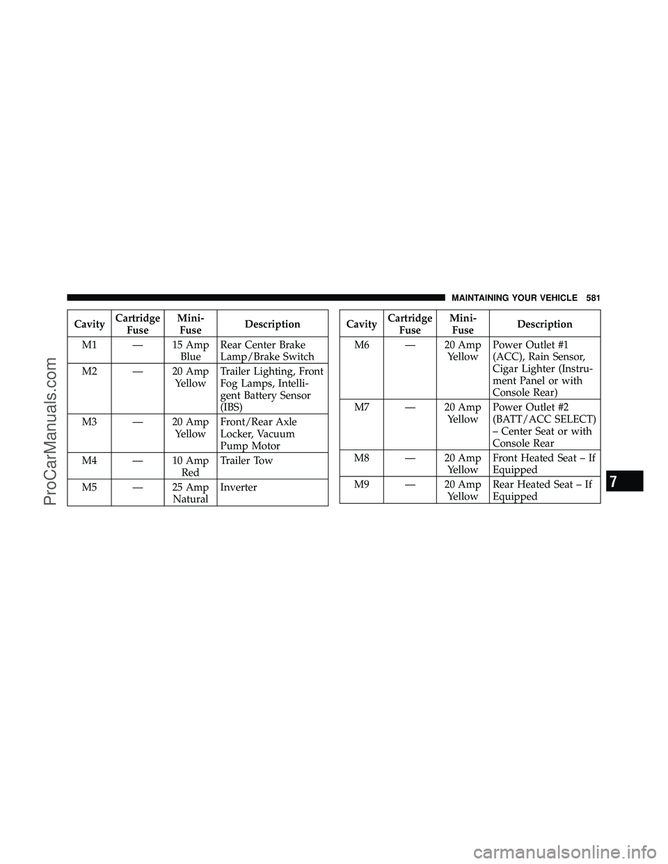
CavityCartridge
Fuse Mini-
Fuse Description
M1 — 15 Amp BlueRear Center Brake
Lamp/Brake Switch
M2 — 20 Amp YellowTrailer Lighting, Front
Fog Lamps, Intelli-
gent Battery Sensor
(IBS)
M3 — 20 Amp YellowFront/Rear Axle
Locker, Vacuum
Pump Motor
M4 — 10 Amp RedTrailer Tow
M5 — 25 Amp NaturalInverterCavity
Cartridge
Fuse Mini-
Fuse Description
M6 — 20 Amp YellowPower Outlet #1
(ACC), Rain Sensor,
Cigar Lighter (Instru-
ment Panel or with
Console Rear)
M7 — 20 Amp YellowPower Outlet #2
(BATT/ACC SELECT)
– Center Seat or with
Console Rear
M8 — 20 Amp YellowFront Heated Seat – If
Equipped
M9 — 20 Amp YellowRear Heated Seat – If
Equipped
7
MAINTAINING YOUR VEHICLE 581
ProCarManuals.com
Page 585 of 643
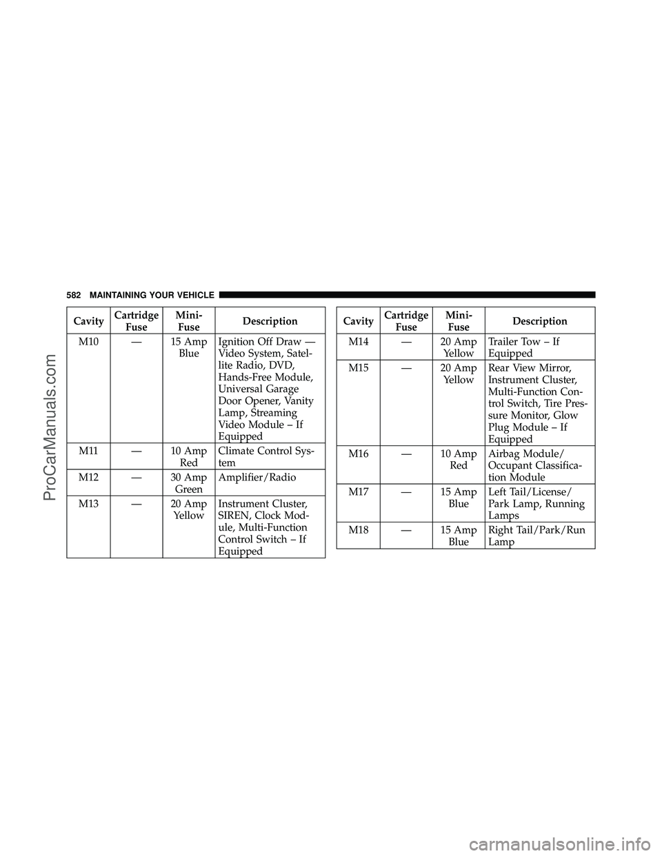
CavityCartridge
Fuse Mini-
Fuse Description
M10 — 15 Amp BlueIgnition Off Draw —
Video System, Satel-
lite Radio, DVD,
Hands-Free Module,
Universal Garage
Door Opener, Vanity
Lamp, Streaming
Video Module – If
Equipped
M11 — 10 Amp RedClimate Control Sys-
tem
M12 — 30 Amp GreenAmplifier/Radio
M13 — 20 Amp YellowInstrument Cluster,
SIREN, Clock Mod-
ule, Multi-Function
Control Switch – If
EquippedCavity
Cartridge
Fuse Mini-
Fuse Description
M14 — 20 Amp YellowTrailer Tow – If
Equipped
M15 — 20 Amp YellowRear View Mirror,
Instrument Cluster,
Multi-Function Con-
trol Switch, Tire Pres-
sure Monitor, Glow
Plug Module – If
Equipped
M16 — 10 Amp RedAirbag Module/
Occupant Classifica-
tion Module
M17 — 15 Amp BlueLeft Tail/License/
Park Lamp, Running
Lamps
M18 — 15 Amp BlueRight Tail/Park/Run
Lamp
582 MAINTAINING YOUR VEHICLE
ProCarManuals.com
Page 586 of 643
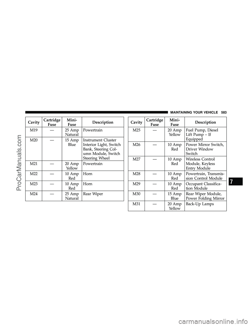
CavityCartridge
Fuse Mini-
Fuse Description
M19 — 25 Amp NaturalPowertrain
M20 — 15 Amp BlueInstrument Cluster
Interior Light, Switch
Bank, Steering Col-
umn Module, Switch
Steering Wheel
M21 — 20 Amp YellowPowertrain
M22 — 10 Amp RedHorn
M23 — 10 Amp RedHorn
M24 — 25 Amp NaturalRear WiperCavity
Cartridge
Fuse Mini-
Fuse Description
M25 — 20 Amp YellowFuel Pump, Diesel
Lift Pump – If
Equipped
M26 — 10 Amp RedPower Mirror Switch,
Driver Window
Switch
M27 — 10 Amp RedWireless Control
Module, Keyless
Entry Module
M28 — 10 Amp RedPowertrain, Transmis-
sion Control Module
M29 — 10 Amp RedOccupant Classifica-
tion Module
M30 — 15 Amp BlueRear Wiper Module,
Power Folding Mirror
M31 — 20 Amp YellowBack-Up Lamps
7
MAINTAINING YOUR VEHICLE 583
ProCarManuals.com
Page 587 of 643
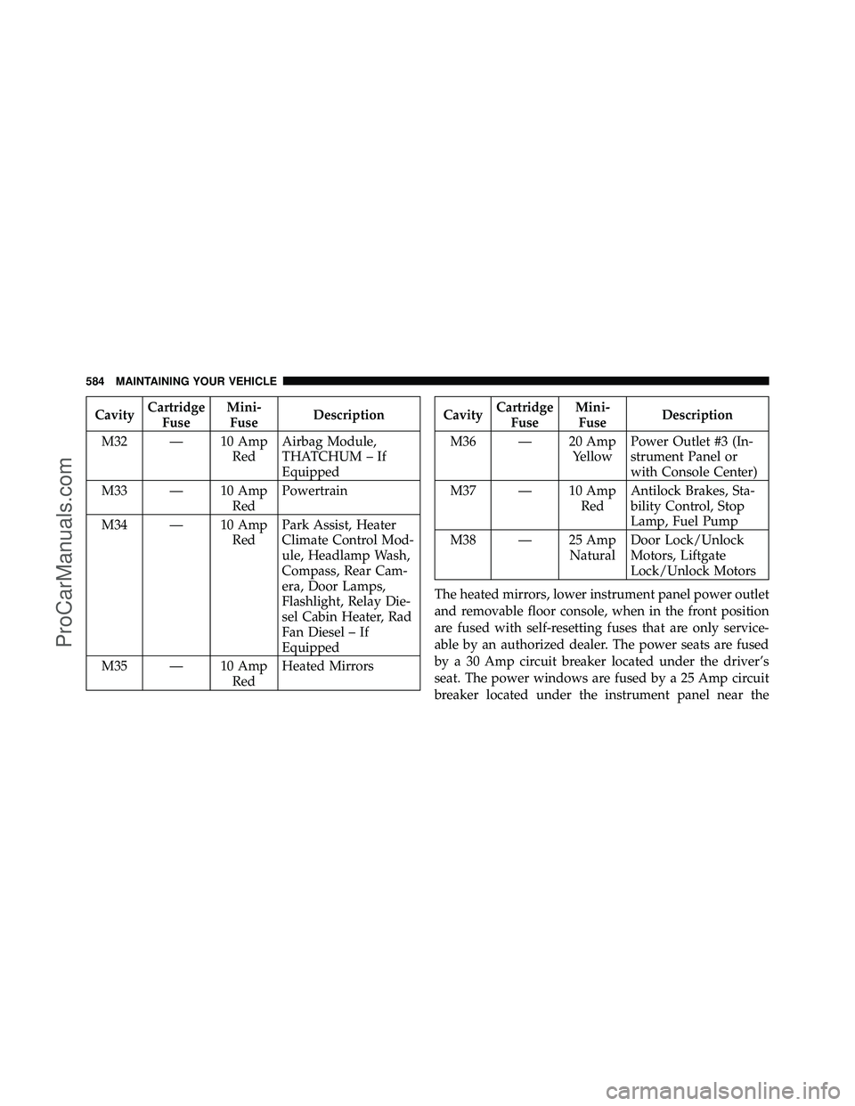
CavityCartridge
Fuse Mini-
Fuse Description
M32 — 10 Amp RedAirbag Module,
THATCHUM – If
Equipped
M33 — 10 Amp RedPowertrain
M34 — 10 Amp RedPark Assist, Heater
Climate Control Mod-
ule, Headlamp Wash,
Compass, Rear Cam-
era, Door Lamps,
Flashlight, Relay Die-
sel Cabin Heater, Rad
Fan Diesel – If
Equipped
M35 — 10 Amp RedHeated MirrorsCavity
Cartridge
Fuse Mini-
Fuse Description
M36 — 20 Amp YellowPower Outlet #3 (In-
strument Panel or
with Console Center)
M37 — 10 Amp RedAntilock Brakes, Sta-
bility Control, Stop
Lamp, Fuel Pump
M38 — 25 Amp NaturalDoor Lock/Unlock
Motors, Liftgate
Lock/Unlock Motors
The heated mirrors, lower instrument panel power outlet
and removable floor console, when in the front position
are fused with self-resetting fuses that are only service-
able by an authorized dealer. The power seats are fused
by a 30 Amp circuit breaker located under the driver’s
seat. The power windows are fused by a 25 Amp circuit
breaker located under the instrument panel near the
584 MAINTAINING YOUR VEHICLE
ProCarManuals.com
Page 588 of 643
steering column. If you experience temporary or perma-
nent loss of these systems, see your authorized dealer for
service.
VEHICLE STORAGE
If you are leaving your vehicle dormant for more than
21 days, you may want to take steps to protect your
battery. You may do the following:
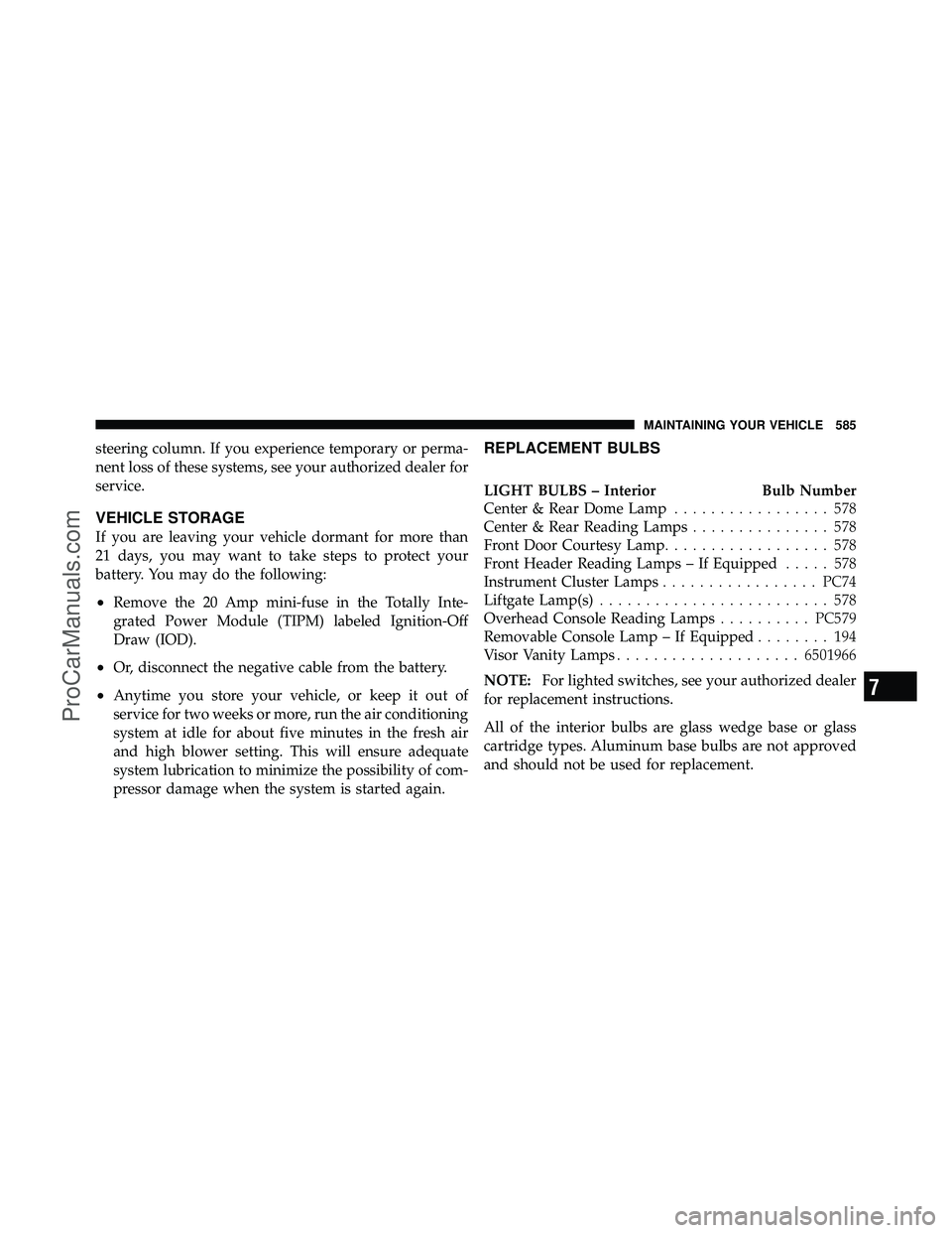
•Remove the 20 Amp mini-fuse in the Totally Inte-
grated Power Module (TIPM) labeled Ignition-Off
Draw (IOD).
•Or, disconnect the negative cable from the battery.
•Anytime you store your vehicle, or keep it out of
service for two weeks or more, run the air conditioning
system at idle for about five minutes in the fresh air
and high blower setting. This will ensure adequate
system lubrication to minimize the possibility of com-
pressor damage when the system is started again.
REPLACEMENT BULBS
LIGHT BULBS – InteriorBulb Number
Center & Rear Dome Lamp ................. 578
Center & Rear Reading Lamps ............... 578
Front Door Courtesy Lamp .................. 578
Front Header Reading Lamps – If Equipped ..... 578
Instrument Cluster Lamps .................PC74
Liftgate Lamp(s) ......................... 578
Overhead Console Reading Lamps ..........PC579
Removable Console Lamp – If Equipped ........ 194
Visor Vanity Lamps .................... 6501966
NOTE: For lighted switches, see your authorized dealer
for replacement instructions.
All of the interior bulbs are glass wedge base or glass
cartridge types. Aluminum base bulbs are not approved
and should not be used for replacement.
7
MAINTAINING YOUR VEHICLE 585
ProCarManuals.com
Page 589 of 643
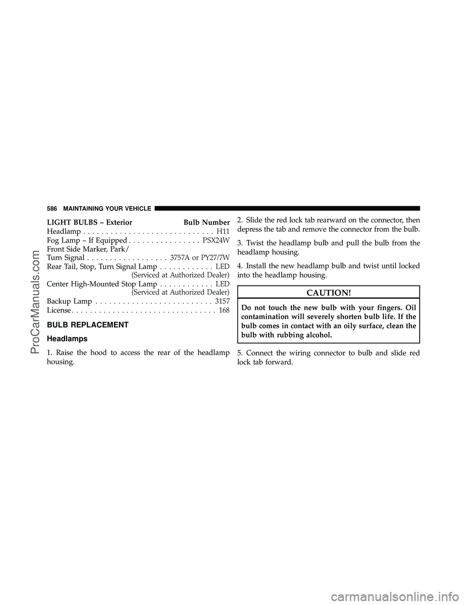
LIGHT BULBS – ExteriorBulb Number
Headlamp ............................. H11
Fog Lamp – If Equipped ................PSX24W
Front Side Marker, Park/
Turn Signal .................. 3757A or PY27/7W
Rear Tail, Stop, Turn Signal Lamp ............ LED
(Serviced at Authorized Dealer)
Center High-Mounted Stop Lamp ............ LED
(Serviced at Authorized Dealer)
Backup Lamp .......................... 3157
License ................................ 168
BULB REPLACEMENT
Headlamps
1. Raise the hood to access the rear of the headlamp
housing. 2. Slide the red lock tab rearward on the connector, then
depress the tab and remove the connector from the bulb.
3. Twist the headlamp bulb and pull the bulb from the
headlamp housing.
4. Install the new headlamp bulb and twist until locked
into the headlamp housing.
CAUTION!
Do not touch the new bulb with your fingers. Oil
contamination will severely shorten bulb life. If the
bulb comes in contact with an oily surface, clean the
bulb with rubbing alcohol.
5. Connect the wiring connector to bulb and slide red
lock tab forward.
586 MAINTAINING YOUR VEHICLE
ProCarManuals.com
Page 590 of 643
Front Park/Turn Signal Lamps
1. Raise the hood to access the rear of the headlamp
housing.
2. Twist the turn signal socket and remove from the
headlamp housing, then pull the bulb out.
3. Push the new bulb into the socket and reinstall the
socket by twisting until locked into the headlamp
housing.
Fog Lamps
NOTE:Access to the fog lamp bulb is from the rear of
the fascia. On the left rear side of the fascia, remove the
push pin and lower the hinged access door on the air
dam. 1. From behind the bumper fascia, or the access panel on
the air dam, squeeze the two tabs on the side of the bulb
socket and pull straight out from the fog lamp.
CAUTION!
Do not touch the new bulb with your fingers. Oil
contamination will severely shorten bulb life. If the
bulb comes in contact with an oily surface, clean the
bulb with rubbing alcohol.
2. Disconnect the wire harness from the bulb.
3. Reconnect the wiring harness to the new bulb and
reinstall by inserting the new bulb straight into the fog
lamp until it locks into place.
7
MAINTAINING YOUR VEHICLE 587
ProCarManuals.com