DODGE CHALLENGER 2010 3.G Owners Manual
Manufacturer: DODGE, Model Year: 2010, Model line: CHALLENGER, Model: DODGE CHALLENGER 2010 3.GPages: 477, PDF Size: 4.79 MB
Page 411 of 477
Cavity Car-tridge
FuseMini-
Fuse
Description
19———
20———
21———
22———
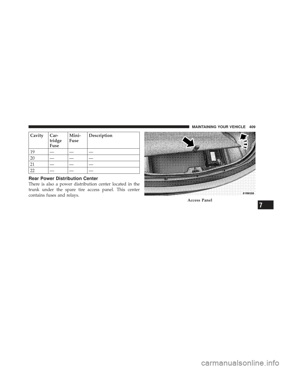
Rear Power Distribution Center
There is also a power distribution center located in the
trunk under the spare tire access panel. This center
contains fuses and relays.
Access Panel
7
MAINTAINING YOUR VEHICLE 409
Page 412 of 477
CAUTION!
•When installing the power distribution center
cover, it is important to ensure the cover is prop-
erly positioned and fully latched. Failure to do so
may allow water to get into the power distribution
center and possibly result in an electrical system
failure.
•When replacing a blown fuse, it is important to
use only a fuse having the correct amperage rating.
The use of a fuse with a rating other than indicated
may result in a dangerous electrical system over-
load. If a properly rated fuse continues to blow, it
indicates a problem in the circuit that must be
corrected.
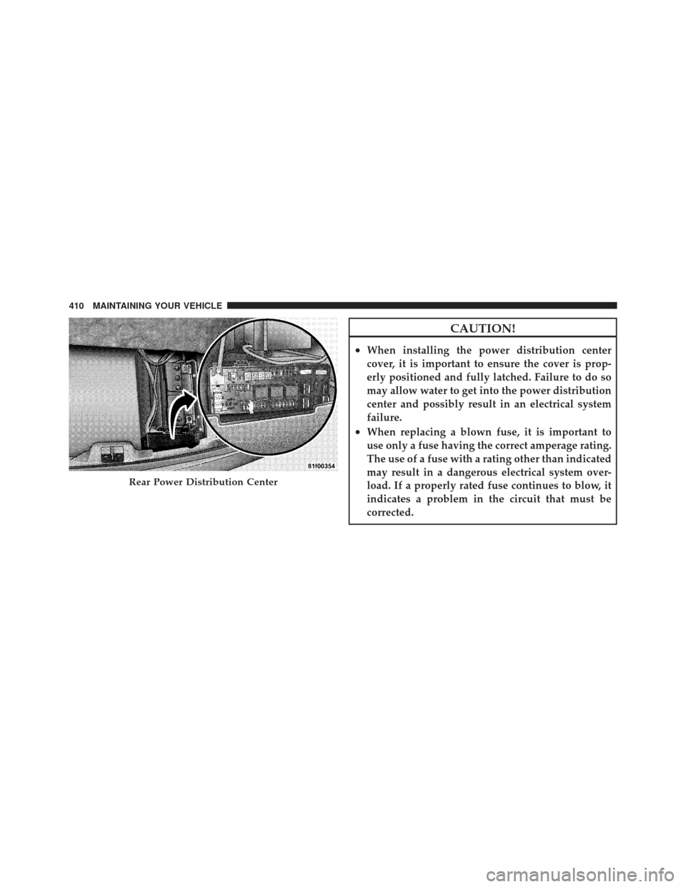
Rear Power Distribution Center
410 MAINTAINING YOUR VEHICLE
Page 413 of 477
Cavity Car-tridge
FuseMini-
Fuse
Description
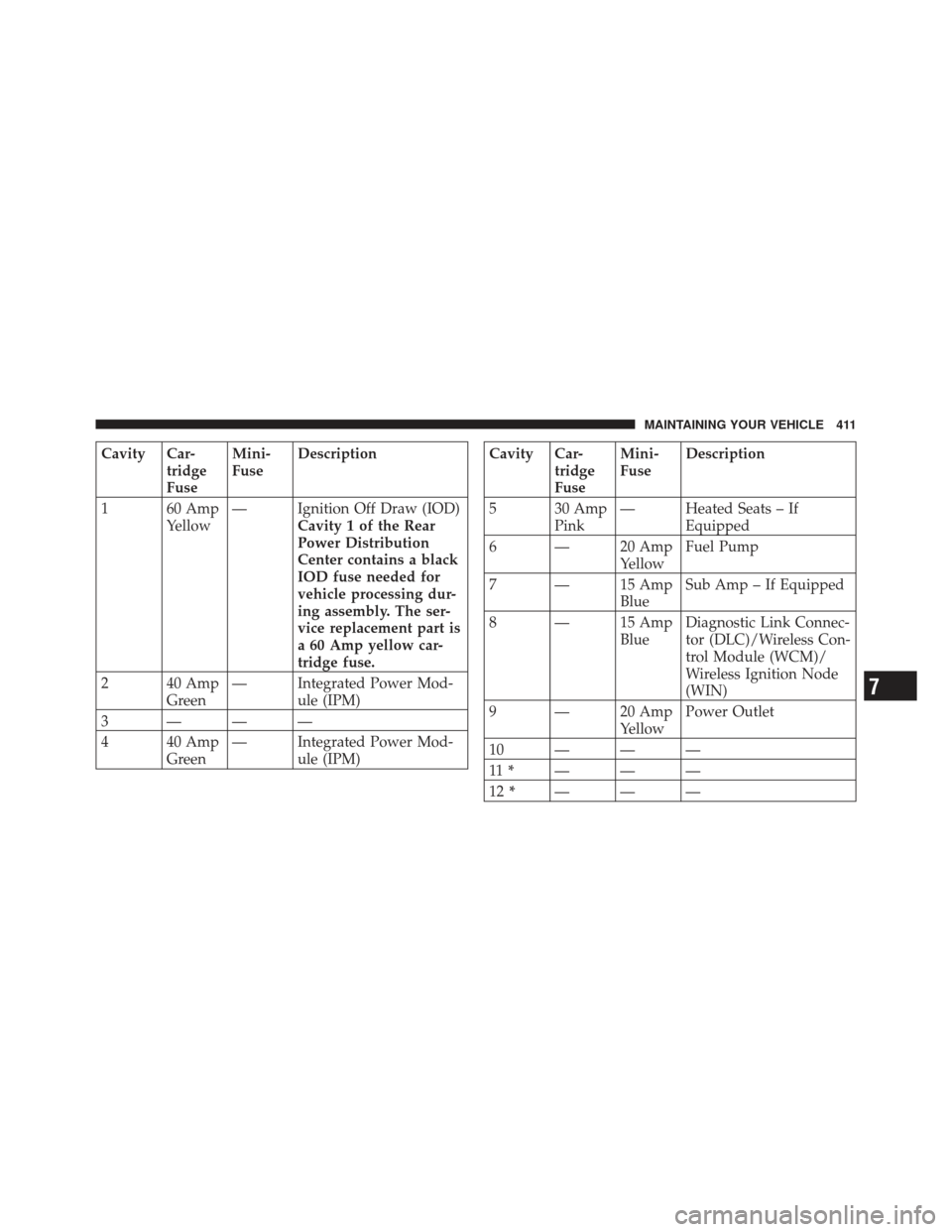
1 60 Amp Yellow— Ignition Off Draw (IOD)
Cavity 1 of the Rear
Power Distribution
Center contains a black
IOD fuse needed for
vehicle processing dur-
ing assembly. The ser-
vice replacement part is
a 60 Amp yellow car-
tridge fuse.
2 40 Amp Green— Integrated Power Mod-
ule (IPM)
3 ———
4 40 Amp Green— Integrated Power Mod-
ule (IPM)Cavity Car-tridge
FuseMini-
Fuse
Description
5 30 Amp Pink— Heated Seats – If
Equipped
6 — 20 Amp YellowFuel Pump
7 — 15 Amp BlueSub Amp – If Equipped
8 — 15 Amp BlueDiagnostic Link Connec-
tor (DLC)/Wireless Con-
trol Module (WCM)/
Wireless Ignition Node
(WIN)
9 — 20 Amp YellowPower Outlet
10———
11 * ———
12 * ———
7
MAINTAINING YOUR VEHICLE 411
Page 414 of 477
Cavity Car-tridge
FuseMini-
Fuse
Description
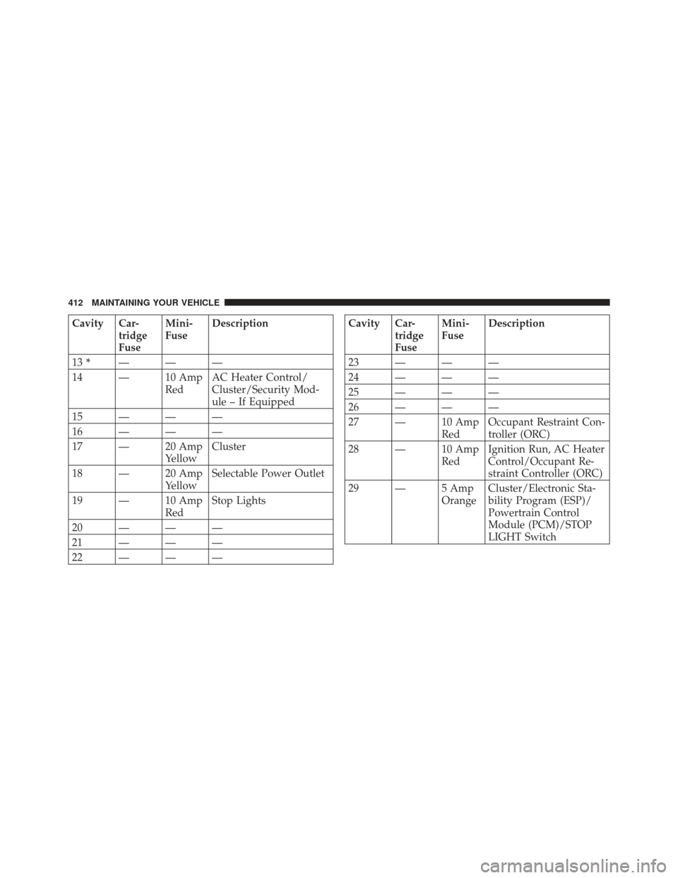
13 * ———
14 — 10 Amp RedAC Heater Control/
Cluster/Security Mod-
ule – If Equipped
15———
16———
17 — 20 Amp YellowCluster
18 — 20 Amp YellowSelectable Power Outlet
19 — 10 Amp RedStop Lights
20———
21———
22———Cavity Car- tridge
FuseMini-
Fuse
Description
23———
24———
25———
26———
27 — 10 Amp RedOccupant Restraint Con-
troller (ORC)
28 — 10 Amp RedIgnition Run, AC Heater
Control/Occupant Re-
straint Controller (ORC)
29 — 5 Amp OrangeCluster/Electronic Sta-
bility Program (ESP)/
Powertrain Control
Module (PCM)/STOP
LIGHT Switch
412 MAINTAINING YOUR VEHICLE
Page 415 of 477
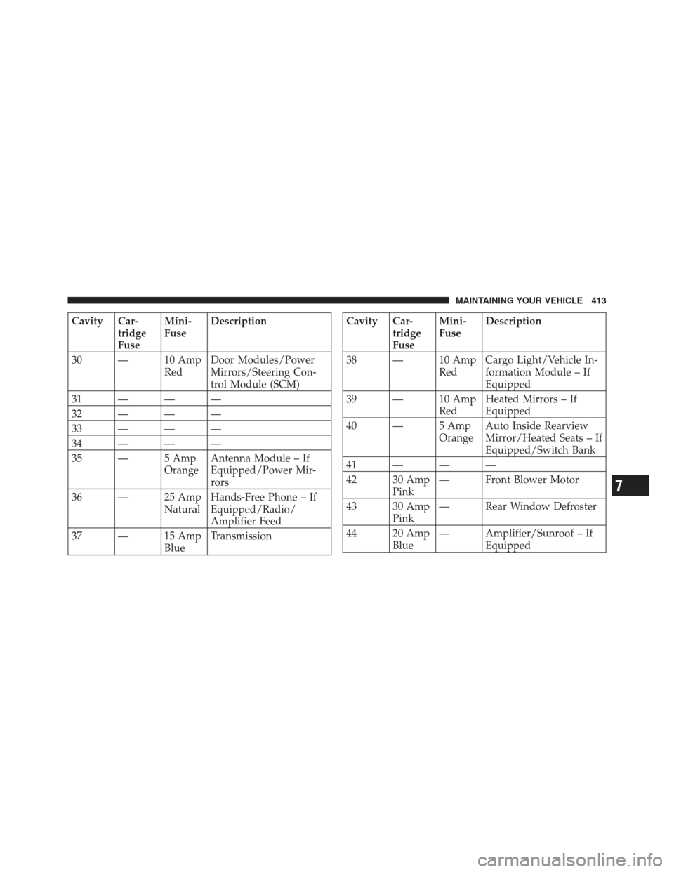
Cavity Car-tridge
FuseMini-
Fuse
Description
30 — 10 Amp RedDoor Modules/Power
Mirrors/Steering Con-
trol Module (SCM)
31———
32———
33———
34———
35 — 5 Amp OrangeAntenna Module – If
Equipped/Power Mir-
rors
36 — 25 Amp NaturalHands-Free Phone – If
Equipped/Radio/
Amplifier Feed
37 — 15 Amp BlueTransmissionCavity Car-
tridge
FuseMini-
Fuse
Description
38 — 10 Amp RedCargo Light/Vehicle In-
formation Module – If
Equipped
39 — 10 Amp RedHeated Mirrors – If
Equipped
40 — 5 Amp OrangeAuto Inside Rearview
Mirror/Heated Seats – If
Equipped/Switch Bank
41———
42 30 Amp Pink— Front Blower Motor
43 30 Amp Pink— Rear Window Defroster
44 20 Amp Blue— Amplifier/Sunroof – If
Equipped
7
MAINTAINING YOUR VEHICLE 413
Page 416 of 477
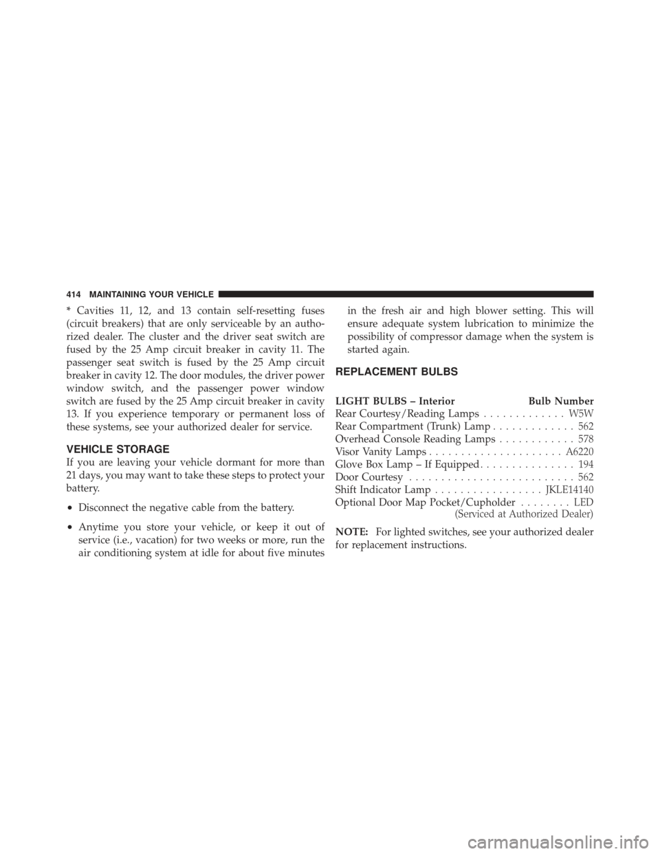
*Cavities 11, 12, and 13 contain self-resetting fuses
(circuit breakers) that are only serviceable by an autho-
rized dealer. The cluster and the driver seat switch are
fused by the 25 Amp circuit breaker in cavity 11. The
passenger seat switch is fused by the 25 Amp circuit
breaker in cavity 12. The door modules, the driver power
window switch, and the passenger power window
switch are fused by the 25 Amp circuit breaker in cavity
13. If you experience temporary or permanent loss of
these systems, see your authorized dealer for service.
VEHICLE STORAGE
If you are leaving your vehicle dormant for more than
21 days, you may want to take these steps to protect your
battery.
•Disconnect the negative cable from the battery.
•Anytime you store your vehicle, or keep it out of
service (i.e., vacation) for two weeks or more, run the
air conditioning system at idle for about five minutes in the fresh air and high blower setting. This will
ensure adequate system lubrication to minimize the
possibility of compressor damage when the system is
started again.
REPLACEMENT BULBS
LIGHT BULBS – Interior
Bulb Number
Rear Courtesy/Reading Lamps ............. W5W
Rear Compartment (Trunk) Lamp ............. 562
Overhead Console Reading Lamps ............ 578
Visor Vanity Lamps ..................... A6220
Glove Box Lamp – If Equipped ............... 194
Door Courtesy .......................... 562
Shift Indicator Lamp ................. JKLE14140
Optional Door Map Pocket/Cupholder ........ LED
(Serviced at Authorized Dealer)
NOTE: For lighted switches, see your authorized dealer
for replacement instructions.
414 MAINTAINING YOUR VEHICLE
Page 417 of 477
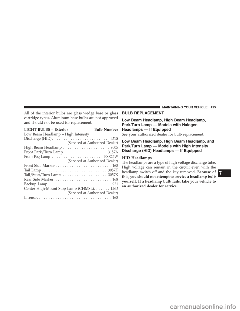
All of the interior bulbs are glass wedge base or glass
cartridge types. Aluminum base bulbs are not approved
and should not be used for replacement.
LIGHT BULBS – Exterior Bulb Number
Low Beam Headlamp – High Intensity
Discharge (HID)......................... D1S
(Serviced at Authorized Dealer)
High Beam Headlamp .................... 9005
Front Park/Turn Lamp ................... 3157A
Front Fog Lamp ...................... PSX24W
(Serviced at Authorized Dealer)
Front Side Marker ........................ 168
Tail Lamp ............................ 3057K
Tail/Stop/Turn Lamp ................... 3057K
Rear Side Marker ........................ 168
Backup Lamp ........................... 921
Center High-Mount Stop Lamp (CHMSL) ....... LED
(Serviced at Authorized Dealer)
License ................................ 168BULB REPLACEMENT
Low Beam Headlamp, High Beam Headlamp,
Park/Turn Lamp — Models with Halogen
Headlamps — If Equipped
See your authorized dealer for bulb replacement.
Low Beam Headlamp, High Beam Headlamp, and
Park/Turn Lamp — Models with High Intensity
Discharge (HID) Headlamps — If Equipped
HID Headlamps
The headlamps are a type of high voltage discharge tube.
High voltage can remain in the circuit even with the
headlamp switch off and the key removed. Because of
this, you should not attempt to service a headlamp bulb
yourself. If a headlamp bulb fails, take your vehicle to
an authorized dealer for service.
7
MAINTAINING YOUR VEHICLE 415
Page 418 of 477
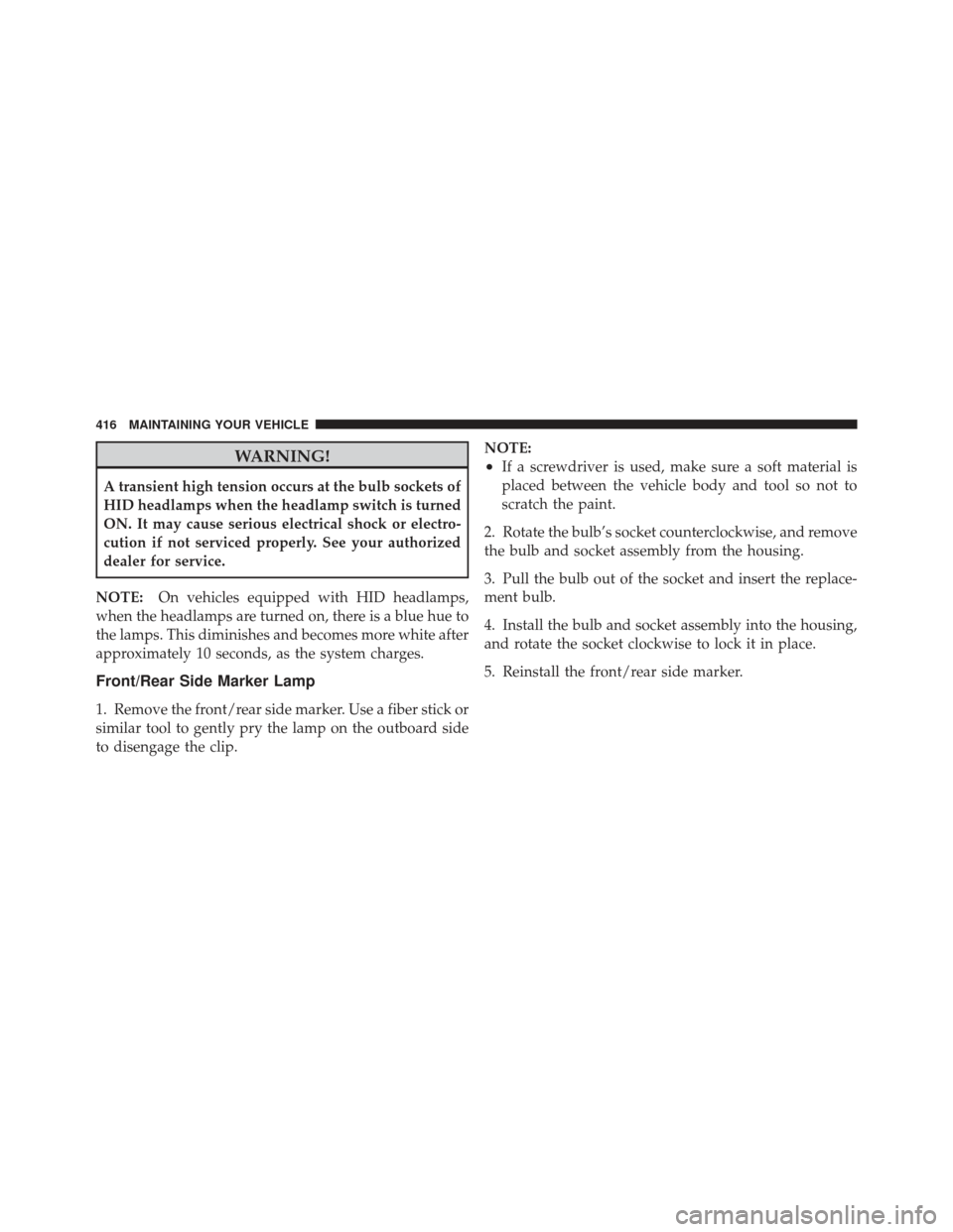
WARNING!
A transient high tension occurs at the bulb sockets of
HID headlamps when the headlamp switch is turned
ON. It may cause serious electrical shock or electro-
cution if not serviced properly. See your authorized
dealer for service.
NOTE: On vehicles equipped with HID headlamps,
when the headlamps are turned on, there is a blue hue to
the lamps. This diminishes and becomes more white after
approximately 10 seconds, as the system charges.
Front/Rear Side Marker Lamp
1. Remove the front/rear side marker. Use a fiber stick or
similar tool to gently pry the lamp on the outboard side
to disengage the clip. NOTE:
•If a screwdriver is used, make sure a soft material is
placed between the vehicle body and tool so not to
scratch the paint.
2. Rotate the bulb’s socket counterclockwise, and remove
the bulb and socket assembly from the housing.
3. Pull the bulb out of the socket and insert the replace-
ment bulb.
4. Install the bulb and socket assembly into the housing,
and rotate the socket clockwise to lock it in place.
5. Reinstall the front/rear side marker.
416 MAINTAINING YOUR VEHICLE
Page 419 of 477
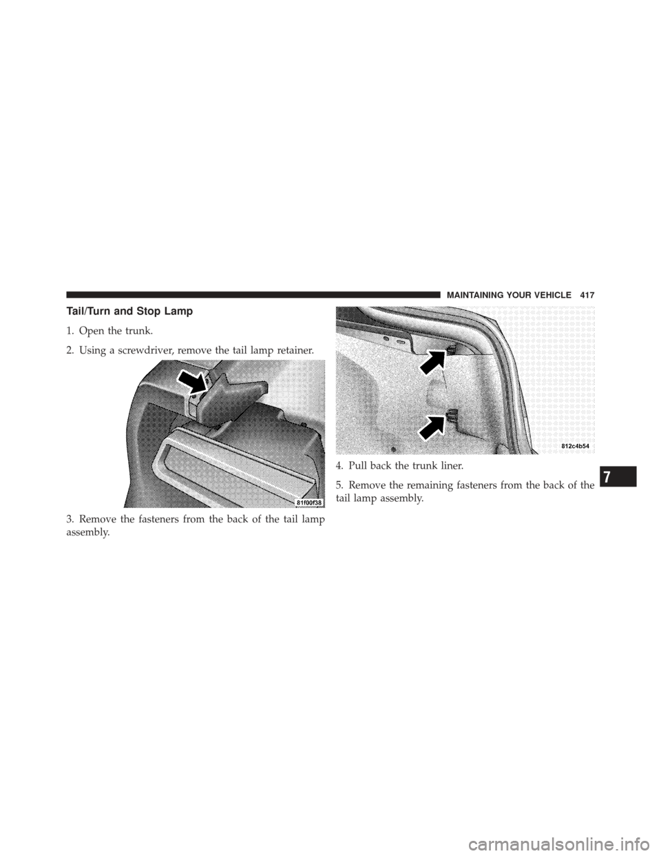
Tail/Turn and Stop Lamp
1. Open the trunk.
2. Using a screwdriver, remove the tail lamp retainer.
3. Remove the fasteners from the back of the tail lamp
assembly.4. Pull back the trunk liner.
5. Remove the remaining fasteners from the back of the
tail lamp assembly.
7
MAINTAINING YOUR VEHICLE 417
Page 420 of 477
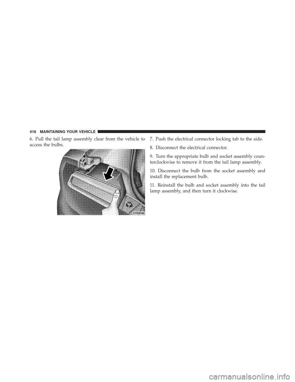
6. Pull the tail lamp assembly clear from the vehicle to
access the bulbs.7. Push the electrical connector locking tab to the side.
8. Disconnect the electrical connector.
9. Turn the appropriate bulb and socket assembly coun-
terclockwise to remove it from the tail lamp assembly.
10. Disconnect the bulb from the socket assembly and
install the replacement bulb.
11. Reinstall the bulb and socket assembly into the tail
lamp assembly, and then turn it clockwise.
418 MAINTAINING YOUR VEHICLE