tow DODGE CHALLENGER 2010 3.G Owner's Manual
[x] Cancel search | Manufacturer: DODGE, Model Year: 2010, Model line: CHALLENGER, Model: DODGE CHALLENGER 2010 3.GPages: 80, PDF Size: 14.2 MB
Page 48 of 80
• The jack and spare tire or TIREFIT kit are stowed under an access cover in the trunk.
• Lift the access cover using the pull strap and remove the fastener securing the sparetire.
• After removing the spare tire, remove the fastener securing the jack.
Preparations For Jacking Or TIREFIT Tire Repair
• Park on a firm, level surface. Avoid ice or slippery areas.
• Set the parking brake and shift the aut omatic transmission into P ARK, or a manual
transmission into REVERSE.
• Turn the ignition to LOCK and turn on the Hazard Warning flasher. • Block both the front and rear of the wheeldiagonally opposite of the jacking position.
For example, if changing the right front tire,
block the left rear wheel.
NOTE: Passengers should not remain in the
vehicle when the vehicle is being jacked.
Jacking And Tire Changing Instructions
WARNING!
Carefully follow these tire changing p rocedures to help prevent personal injury or
damage to your vehicle: Always park on a firm, level surface as far from the edge of
the roadway as possible before raising the vehicle.
• Remove the spare tire, jack and lug wrench.
• If equipped with steel wheels, do not remove the wheel cover at this time. If equipped with aluminum wheels where the center cap covers the lug nuts, use the lug wrench to
pry the center cap off carefully before raising the vehicle.
• Loosen (but do not remove) the wheel lug nuts by turning them to the left one turn while the wheel is still on the ground.
• Assemble the jack and jacking tools. Connect the jack handle driver to the extension, then to the lug wrench.
WHAT TO DO IN EMERGENCIES
46
Page 49 of 80
• Place the jack underneath the lift area that is closest to the flat tire. Turn the jackscrew clockwise to firmly engage the jack saddle with the lift area of the sill flange.
• Raise the vehicle by turning the jack screw clockwise. Raise the vehicle only until the tire just clears the surface and enough clearance is obtained to install the spare tire.
WARNING!
Raising the vehicle higher than necessary can make the vehicle less stable and cause
an accident. It could slip off the jack and hurt someone near it. Raise the vehicle only
enough to remove the tire.
• Remove the lug nuts, wheel cover (if equipped) and wheel.
• Position the spare wheel/tire on the vehicle and install the lug nuts with the cone-shaped end toward the wheel. Do NOT attempt to install a center cap or wheel
cover on the compact spare. Lightly tighten the lug nuts. To avoid the risk of forcing
the vehicle off the jack, do not tighten the nuts fully until the vehicle has been
lowered.
• Lower the vehicle by turning the jack screw to the left, and remove the jack and wheel blocks.
• Finish tightening the lug nuts. Push do wn on the wrench while tightening for
increased leverage. Alternate nuts until each one has been tightened twice. The
correct wheel nut tightness is 100 ft lbs (135 N•m). If in doubt about the correct
tightness, have them checked with a tor que wrench by your authorized dealer or at a
service station.
47
WHAT TO DO IN EMERGENCIES
Page 50 of 80
WARNING!
To assure that spare tires, flat or inflated, are securely stowed, spares must be stowed
with the valve stem facing the ground.
• Secure the tire, jack (base of jack fac es rear of vehicle), and tools in their proper
locations.
TIREFIT Instructions
• TIREFIT will temporarily seal small punctures up to14in.(6 mm) in the tire tread allowing
you to drive your vehicle up to 100 mi (160 km) with a maximum speed of 55 mph
(90 km/hr). TIREFIT can be used in outside temperatures down to approximately -4°F
(-20°C).
NOTE: Do not remove foreign objects (e.g., screws or nails) from the tire.
• Verify that the valve stem is close to the ground.
• Put on the gloves from the TIREFIT Kit Accessory Storage Compartment.
• Turn the Mode Select knob to the Sealant Mode position
.
• Remove the Yellow Cap from the fitting at the end of the Clear Sealant Hose.
• Remove the valve stem cap and screw the fitting at the end of the Clear Sealant Hose onto the valve stem.
• Insert the Power Plug into the vehicle’s 12-volt power outlet.
• Start the engine and then press the Power button
. The sealant (white fluid) will
flow from the Sealant Bottle through the Clear Sealant Hose and into the tire.
NOTE:
• Sealant may leak out through the puncture in the tire.
• If the sealant (white fluid) does not flow withi n0–10secondsthrough the Clear
Sealant Hose: • Press the Power button
to turn OFF the TIREFIT kit.
• Disconnect the Clear Sealant Hose and make sure the valve stem is free of debris.
• Repeat previous steps to verify sealant will flow, making sure the Mode Select knob is in Sealant Mode
.
• Continue to operate the pump until seal ant is no longer flowing through the hose
(typically takes 30 - 70 seconds). As the sealant flows through the Clear Sealant Hose,
the pressure gauge can read as high as 70 psi. The pressure gauge will decrease
quickly from approximately 70 psi to the actual tire pressure when the sealant bottle is
empty.
• The pump will start to inject air into the tire immediately after the sealant bottle is
empty. Continue to operate the pump and inflate the tire to the pressure indicated on
the Tire and Loading Information label on the driver's side door opening. Check the
tire pressure by looking at the pressure gauge.
WHAT TO DO IN EMERGENCIES
48
Page 56 of 80
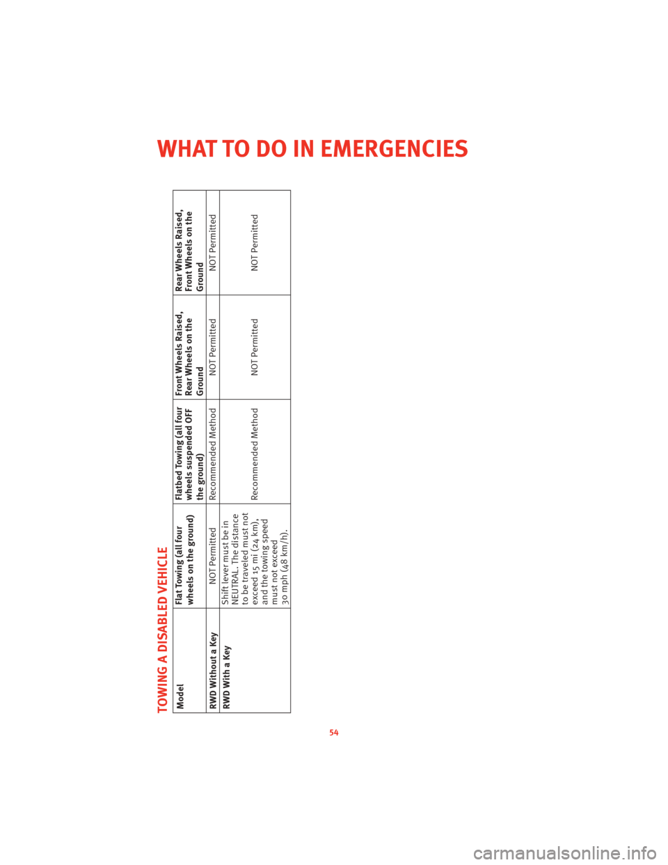
TOWING A DISABLED VEHICLEModelFlat Towing (all four
wheels on the ground)Flatbed Towing (all four
wheels suspended OFF
the ground)Front Wheels Raised,
Rear Wheels on the
GroundRear Wheels Raised,
Front Wheels on the
Ground
RWD Without a Key NOT Permitted Recommended Method NOT Permitted
NOT Permitted
RWD With a Key Shift lever must be in
NEUTRAL. The distance
to be traveled must not
exceed 15 mi (24 km),
and the towing speed
must not exceed
30 mph (48 km/h).Recommended Method NOT Permitted
NOT Permitted
54
WHAT TO DO IN EMERGENCIES
Page 77 of 80
MOPAR®ACCESSORIES
• The following highlights just some of the authentic Dodge Accessories by MOPAR®
that have been engineered to customize your Dodge Challenger.
• To see the full line of accessories, sto p by your Dodge dealer or visitMOPAR.com.
CHROME:
• Chrome Fuel Filler Door • Cat-Back Dual Exhaust System• 20-Inch Chrome Aluminum
Wheel
EXTERIOR:
• Rear Go-Wing Spoiler • Body Decal Kit • T/A Hood
• Molded Splash Guards • Full Vehicle Cover
INTERIOR:
• Premium Carpet Floor Mats • Katzkin Leather Seats • Bright Pedal Kit
• Door Sill Guards • Premium Carpet Cargo Mat
ELECTRONICS:
• Portable Navigation Systems • Uconnect™ Web (WiFi) • Uconnect™ Phone
•iPod
®Adapter • Media Center 730N (RER
Navigation Radio) • Remote Start
• Kicker
®Double
SubWoofer
PERFORMANCE:
• Cold Air Intake Kits • Coilover Suspension Kits • Strut Tower Brace
• Performance Brake Pads • Performance Air Filters
•iPod
®is a registered trademark of Apple, Inc.
• Kicker®is a registered trademark of Stillwater Designs and Audio, Inc.
75
MOPAR ACCESSORIES