fuses DODGE CHALLENGER 2012 3.G User Guide
[x] Cancel search | Manufacturer: DODGE, Model Year: 2012, Model line: CHALLENGER, Model: DODGE CHALLENGER 2012 3.GPages: 124, PDF Size: 4.99 MB
Page 3 of 124

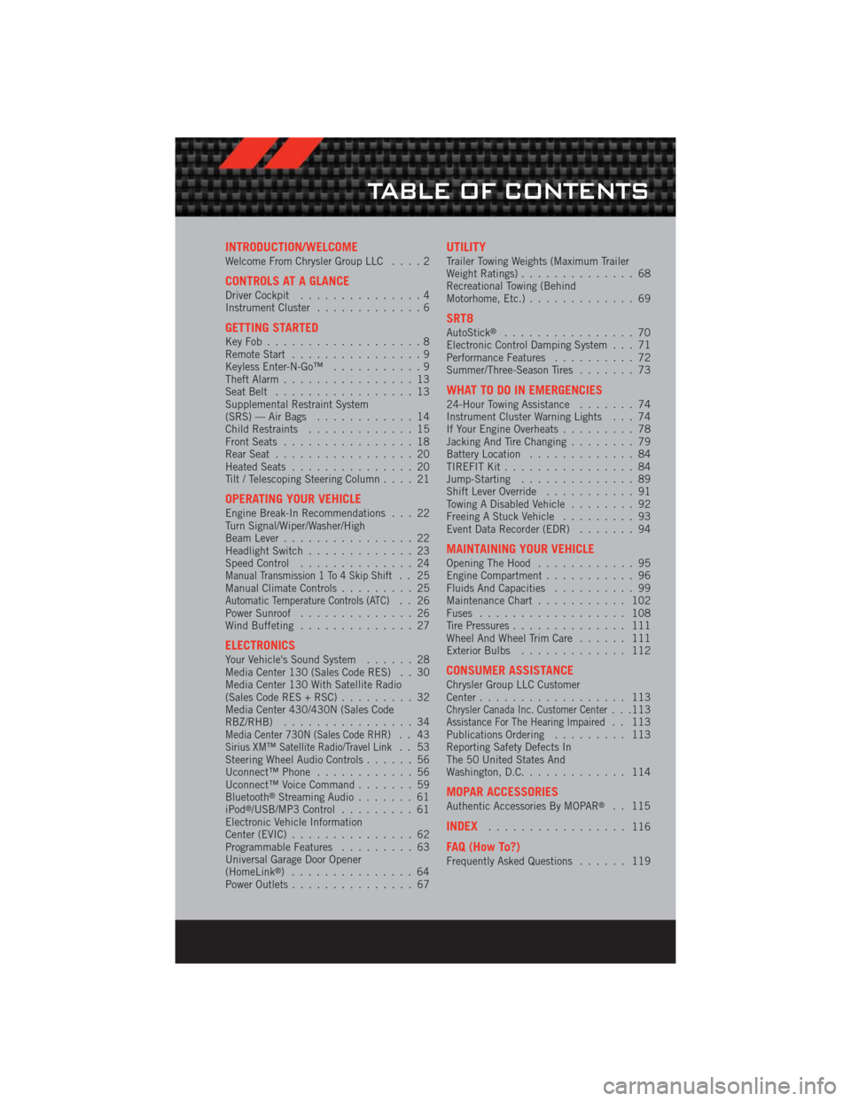
INTRODUCTION/WELCOMEWelcome From Chrysler Group LLC....2
CONTROLS AT A GLANCEDriver Cockpit...............4
Instrument Cluster .............6
GETTING STARTEDKeyFob...................8
Remote Start................9
Keyless Enter-N-Go™ ...........9
Theft Alarm ................13
Seat Belt .................13
Supplemental Restraint System
(SRS) — Air Bags ............14
Child Restraints .............15
Front Seats ................18
Rear Seat .................20
Heated Seats ...............20
Tilt / Telescoping Steering Column ....21
OPERATING YOUR VEHICLEEngine Break-In Recommendations . . . 22
Turn Signal/Wiper/Washer/High
Beam Lever................22
Headlight Switch .............23
Speed Control ..............24
Manual Transmission 1 To 4 Skip Shift.. 25
Manual Climate Controls .........25
Automatic Temperature Controls (ATC).. 26
Power Sunroof ..............26
Wind Buffeting ..............27
ELECTRONICSYour Vehicle's Sound System ......28
Media Center 130 (Sales Code RES) . . 30
Media Center 130 With Satellite Radio
(Sales Code RES + RSC) .........32
Media Center 430/430N (Sales Code
RBZ/RHB) ................34
Media Center 730N (Sales Code RHR).. 43Sirius XM™ Satellite Radio/Travel Link.. 53
Steering Wheel Audio Controls ......56
Uconnect™ Phone ............56
Uconnect™ Voice Command .......59
Bluetooth
®Streaming Audio .......61
iPod®/USB/MP3 Control .........61
Electronic Vehicle Information
Center (EVIC) ...............62
Programmable Features .........63
Universal Garage Door Opener
(HomeLink
®) ...............64
Power Outlets ...............67
UTILITYTrailer Towing Weights (Maximum Trailer
Weight Ratings) ..............68
Recreational Towing (Behind
Motorhome, Etc.) .............69
SRT8AutoStick®................70
Electronic Control Damping System . . . 71
Performance Features ..........72
Summer/Three-Season Tires .......73
WHAT TO DO IN EMERGENCIES24-Hour Towing Assistance.......74
Instrument Cluster Warning Lights . . . 74
If Your Engine Overheats .........78
Jacking And Tire Changing ........79
Battery Location .............84
TIREFIT Kit ................84
Jump-Starting ..............89
Shift Lever Override ...........91
Towing A Disabled Vehicle ........92
Freeing A Stuck Vehicle .........93
Event Data Recorder (EDR) .......94
MAINTAINING YOUR VEHICLEOpening The Hood............95
Engine Compartment ...........96
Fluids And Capacities ..........99
Maintenance Chart ........... 102
Fuses .................. 108
Tire Pressures .............. 111
Wheel And Wheel Trim Care ...... 111
Exterior Bulbs ............. 112
CONSUMER ASSISTANCEChrysler Group LLC Customer
Center.................. 113
Chrysler Canada Inc. Customer Center...113Assistance For The Hearing Impaired. . 113
Publications Ordering ......... 113
Reporting Safety Defects In
The 50 United States And
Washington, D.C. ............ 114
MOPAR ACCESSORIESAuthentic Accessories By MOPAR®. . 115
INDEX................. 116
FAQ (How To?)Frequently Asked Questions ...... 119
TABLE OF CONTENTS
Page 110 of 124

FUSES
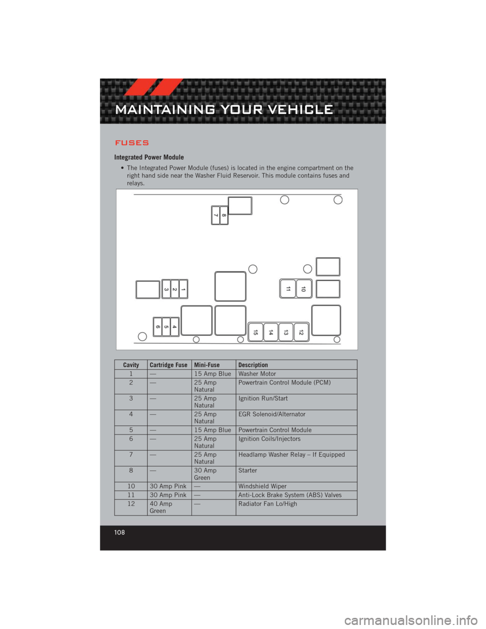
Integrated Power Module
• The Integrated Power Module (fuses) is located in the engine compartment on theright hand side near the Washer Fluid Reservoir. This module contains fuses and
relays.
Cavity Cartridge Fuse Mini-Fuse Description
1 — 15 Amp Blue Washer Motor
2 — 25 Amp
Natural Powertrain Control Module (PCM)
3 — 25 Amp
Natural Ignition Run/Start
4 — 25 Amp
Natural EGR Solenoid/Alternator
5 — 15 Amp Blue Powertrain Control Module
6 — 25 Amp
Natural Ignition Coils/Injectors
7 — 25 Amp
Natural Headlamp Washer Relay – If Equipped
8 — 30 Amp
Green Starter
10 30 Amp Pink — Windshield Wiper
11 30 Amp Pink — Anti-Lock Brake System (ABS) Valves
12 40 Amp Green —
Radiator Fan Lo/High
MAINTAINING YOUR VEHICLE
108
Page 111 of 124

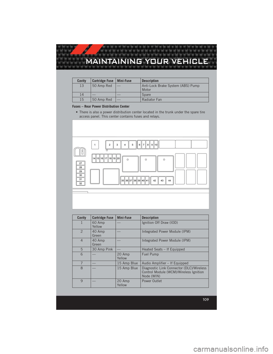
Cavity Cartridge Fuse Mini-Fuse Description13 50 Amp Red — Anti-Lock Brake System (ABS) Pump
Motor
14 — —Spare
15 50 Amp Red — Radiator Fan
Fuses – Rear Power Distribution Center • There is also a power distribution center located in the trunk under the spare tireaccess panel. This center contains fuses and relays.
Cavity Cartridge Fuse Mini-Fuse Description
1 60 Amp Yellow — Ignition Off Draw (IOD)
2 40 Amp Green —
Integrated Power Module (IPM)
4 40 Amp Green —
Integrated Power Module (IPM)
5 30 Amp Pink — Heated Seats – If Equipped
6 — 20 Amp
Yellow Fuel Pump
7 — 15 Amp Blue Audio Amplifier – If Equipped
8 — 15 Amp Blue Diagnostic Link Connector (DLC)/Wireless
Control Module (WCM)/Wireless Ignition
Node (WIN)
9 — 20 Amp
Yellow Power Outlet
MAINTAINING YOUR VEHICLE
109