buttons DODGE CHALLENGER 2015 3.G Owners Manual
[x] Cancel search | Manufacturer: DODGE, Model Year: 2015, Model line: CHALLENGER, Model: DODGE CHALLENGER 2015 3.GPages: 603, PDF Size: 14.97 MB
Page 23 of 603
NOTE:
•The front courtesy overhead console and door cour-
tesy lights do not turn on if the dimmer control is in
the#Dome ON#position (extreme top position).
•The Illuminated Entry system will not operate if the
dimmer control is in the “Dome defeat” position
(extreme bottom position).
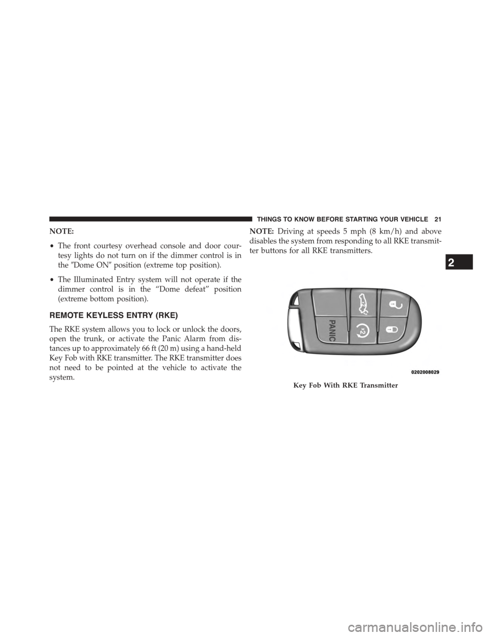
REMOTE KEYLESS ENTRY (RKE)
The RKE system allows you to lock or unlock the doors,
open the trunk, or activate the Panic Alarm from dis-
tances up to approximately 66 ft (20 m) using a hand-held
Key Fob with RKE transmitter. The RKE transmitter does
not need to be pointed at the vehicle to activate the
system.
NOTE:Driving at speeds 5 mph (8 km/h) and above
disables the system from responding to all RKE transmit-
ter buttons for all RKE transmitters.
Key Fob With RKE Transmitter
2
THINGS TO KNOW BEFORE STARTING YOUR VEHICLE 21
Page 34 of 603
Automatic Unlock Doors On Exit
The doors will unlock automatically if:
1. The Automatic Unlock Doors On Exit feature is en-
abled.
2. The transmission was in gear and the vehicle speed
returned to 0 mph (0 km/h).
3. The transmission is in PARK.
4. The driver door is opened.
5. The doors were not previously unlocked.
6. The vehicle speed is 0 mph (0 km/h).
Automatic Unlock Doors On Exit Programming
The Automatic Unlock Doors On Exit feature can be
enabled or disabled. Refer to “Uconnect® Settings” in
“Understanding Your Instrument Panel” for further in-
formation.
NOTE:Use the Automatic Unlock Doors On Exit feature
in accordance with local laws.
KEYLESS ENTER-N-GO™
The Passive Entry system is an enhancement to the
vehicle’s Remote Keyless Entry (RKE) system and a
feature of Keyless Enter-N-Go™. This feature allows you
to lock and unlock the vehicle’s door(s) without having to
push the RKE transmitter lock or unlock buttons.
32 THINGS TO KNOW BEFORE STARTING YOUR VEHICLE
Page 109 of 603
NOTE:The ASSIST and 9–1–1 features operate through
the Uconnect® Access service. These buttons will only
operate as long as your Uconnect® Access service is
active. Refer to your “Uconnect® System supplement
manual” for further information.
ASSIST Call
The ASSIST Button is used to automatically connect you
to any one of the following support centers:
•Roadside Assistance – If you get a flat tire, or need a
tow, just press the Assist button and you’ll be con-
nected to someone who can help. Roadside Assistance
will know what vehicle you’re driving and its location.
Additional fees may apply for roadside Assistance.
•Uconnect® Access Customer Care – In-vehicle support
for Uconnect® Access and Uconnect® Access Via
Mobile features.
•Vehicle Customer Care – Total support for all other
vehicle issues.
9-1-1 Call
1. Press the 9-1-1 Call button on the Rearview Mirror.
NOTE:In case the 9-1-1 Call button is pushed in error,
there will be a 10 second delay before the 9-1-1 Call
system initiates a call to a 9-1-1 operator. To cancel the
9-1-1 Call connection, press the 9-1-1 Call button on the
Rearview Mirror or press the cancellation button on the
Phone Screen. Termination of the 9-1-1 Call will turn the
green LED light on the Rearview Mirror off.
2. The LED light located between the Assist and 9-1-1
buttons on the Rearview Mirror will turn green once a
connection to a 9-1-1 operator has been made.
3
UNDERSTANDING THE FEATURES OF YOUR VEHICLE 107
Page 112 of 603
If the 9-1-1 Call system detects a malfunction, any of the
following may occur at the time the malfunction is
detected, and at the beginning of each ignition cycle:
•The Rearview Mirror light located between the Assist
and 9-1-1 buttons will continuously be illuminated
red.
•The Phone Screen will display the following message
“Vehicle phone requires service. Please contact your
dealer.”
•An In-Vehicle Audio message will state “Vehicle phone
requires service. Please contact your dealer.”
WARNING!
•Ignoring the Rearview Mirror light could mean you
will not have 9-1-1 Call services. If the Rearview
Mirror light is illuminated, have an authorized
dealer service the 9-1-1 Call system immediately.
•The Occupant Restraint Control module turns on
the Air Bag Warning Light on the instrument panel
if a malfunction in any part of the system is
detected. If the Air Bag Warning Light is illumi-
nated, the air bag system may not be working
properly and the 9-1-1 system may not be able to
send a signal to a 9-1-1 operator. If the Air Bag
Warning Light is illuminated, have an authorized
dealer service the ORC system immediately.
11 0 U N D E R S TA N D I N G T H E F E AT U R E S O F Y O U R V E H I C L E
Page 130 of 603
WARNING!
•Adjusting a seat while driving may be dangerous.
Moving a seat while driving could result in loss of
control which could cause a collision and serious
injury or death.
•Seats should be adjusted before fastening the seat
belts and while the vehicle is parked. Serious
injury or death could result from a poorly adjusted
seat belt.
•Do not ride with the seatback reclined so that the
shoulder belt is no longer resting against your
chest. In a collision you could slide under the seat
belt, which could result in serious injury or death.
CAUTION!
Do not place any article under a power seat or
impede its ability to move as it may cause damage to
the seat controls. Seat travel may become limited if
movement is stopped by an obstruction in the seat’s
path.
Front Heated Seats — If Equipped
The front heated seats control buttons are located within
the Uconnect® system. You can gain access to the control
buttons through the climate screen or the controls screen.
•Press the heated seat buttononce to turn the High
setting ON.
•Press the heated seat buttona second time to turn
the Low setting ON.
•Press the heated seat buttona third time to turn
the heating elements OFF.
128 UNDERSTANDING THE FEATURES OF YOUR VEHICLE
Page 132 of 603
Front Ventilated Seats — If Equipped
Located in the seat cushion and seat back are small fans
that draw the air from the passenger compartment and
blow air through fine perforations in the seat cover to
help keep the driver and front passenger cooler in higher
ambient temperatures. The fans operate at two speeds,
HIGH and LOW.
The front ventilated seats control buttons are located
within the Uconnect® system. You can gain access to the
control buttons through the climate screen or the controls
screen.
•Press the ventilated seat buttononce to choose
HIGH.
•Press the ventilated seat buttona second time to
choose LOW.
•Press the ventilated seat buttona third time to
turn the ventilated seat OFF.
NOTE:The engine must be running for the ventilated
seats to operate.
Vehicles Equipped With Remote Start
On models that are equipped with remote start, the
ventilated seats can be programed to come on during a
remote start.
This feature can be programmed through the Uconnect®
system. Refer to “Uconnect® Settings” in “Understand-
ing Your Instrument Panel” for further information.
Manual Forward Or Rearward Adjustment
The adjusting bar is located at the front of the seat, near
the floor. Pull the bar upward to move the seat forward or
rearward. Release the bar once the seat is in the desired
position. Using body pressure, move forward and rear-
ward on the seat to be sure that the seat adjusters have
latched.
130 UNDERSTANDING THE FEATURES OF YOUR VEHICLE
Page 157 of 603
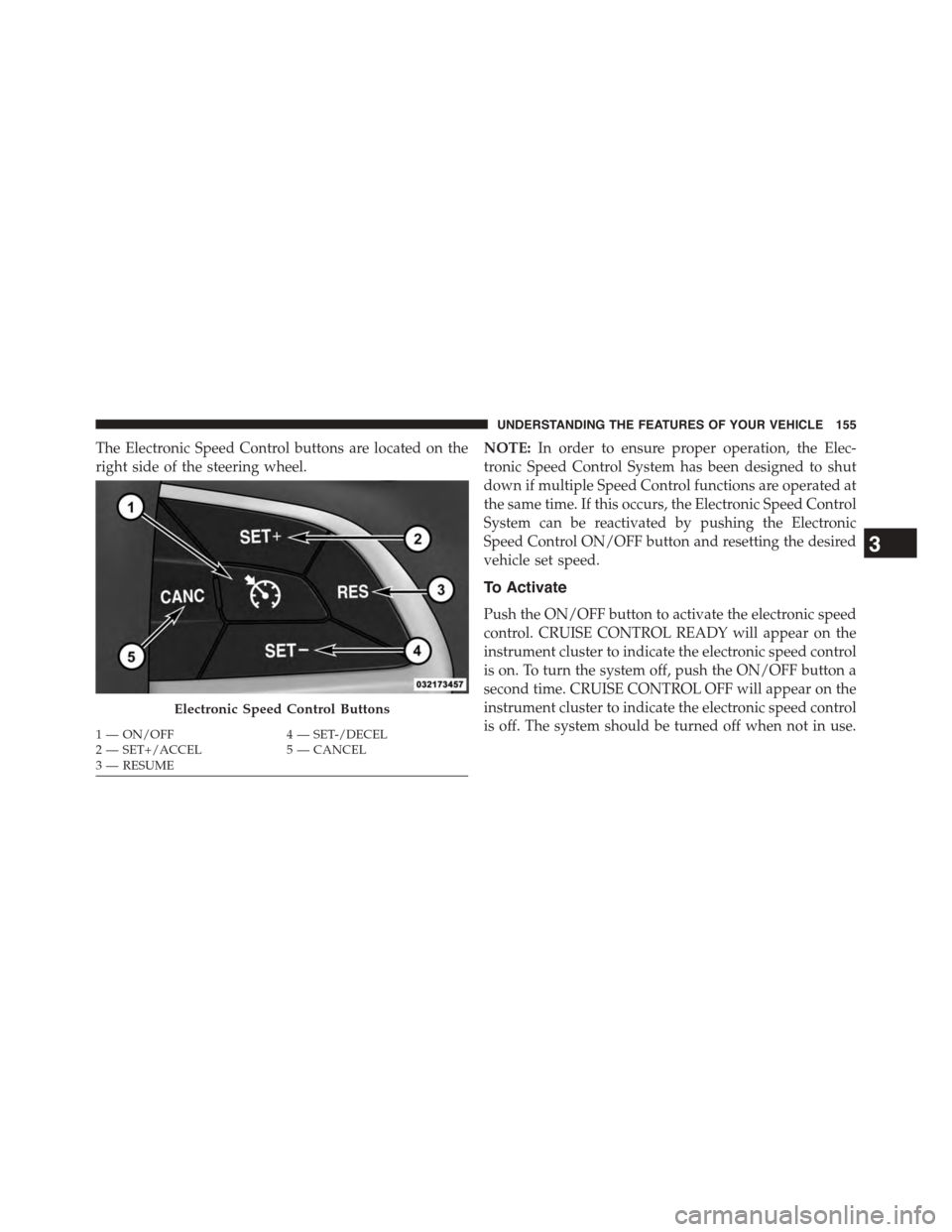
The Electronic Speed Control buttons are located on the
right side of the steering wheel.
NOTE:In order to ensure proper operation, the Elec-
tronic Speed Control System has been designed to shut
down if multiple Speed Control functions are operated at
the same time. If this occurs, the Electronic Speed Control
System can be reactivated by pushing the Electronic
Speed Control ON/OFF button and resetting the desired
vehicle set speed.
To Activate
Push the ON/OFF button to activate the electronic speed
control. CRUISE CONTROL READY will appear on the
instrument cluster to indicate the electronic speed control
is on. To turn the system off, push the ON/OFF button a
second time. CRUISE CONTROL OFF will appear on the
instrument cluster to indicate the electronic speed control
is off. The system should be turned off when not in use.
Electronic Speed Control Buttons
1—ON/OFF4—SET-/DECEL2—SET+/ACCEL5—CANCEL3—RESUME
3
UNDERSTANDING THE FEATURES OF YOUR VEHICLE 155
Page 163 of 603
•Normal (fixed speed) cruise control mode is for cruis-
ing at a constant preset speed. For additional informa-
tion, refer to “Normal (Fixed Speed) Cruise Control
Mode” in this section.
NOTE:The system will not react to preceding vehicles.
Always be aware of the mode selected.
You can change the mode by using the Cruise Control
buttons. The two control modes function differently.
Always confirm which mode is selected.
Adaptive Cruise Control (ACC) Operation
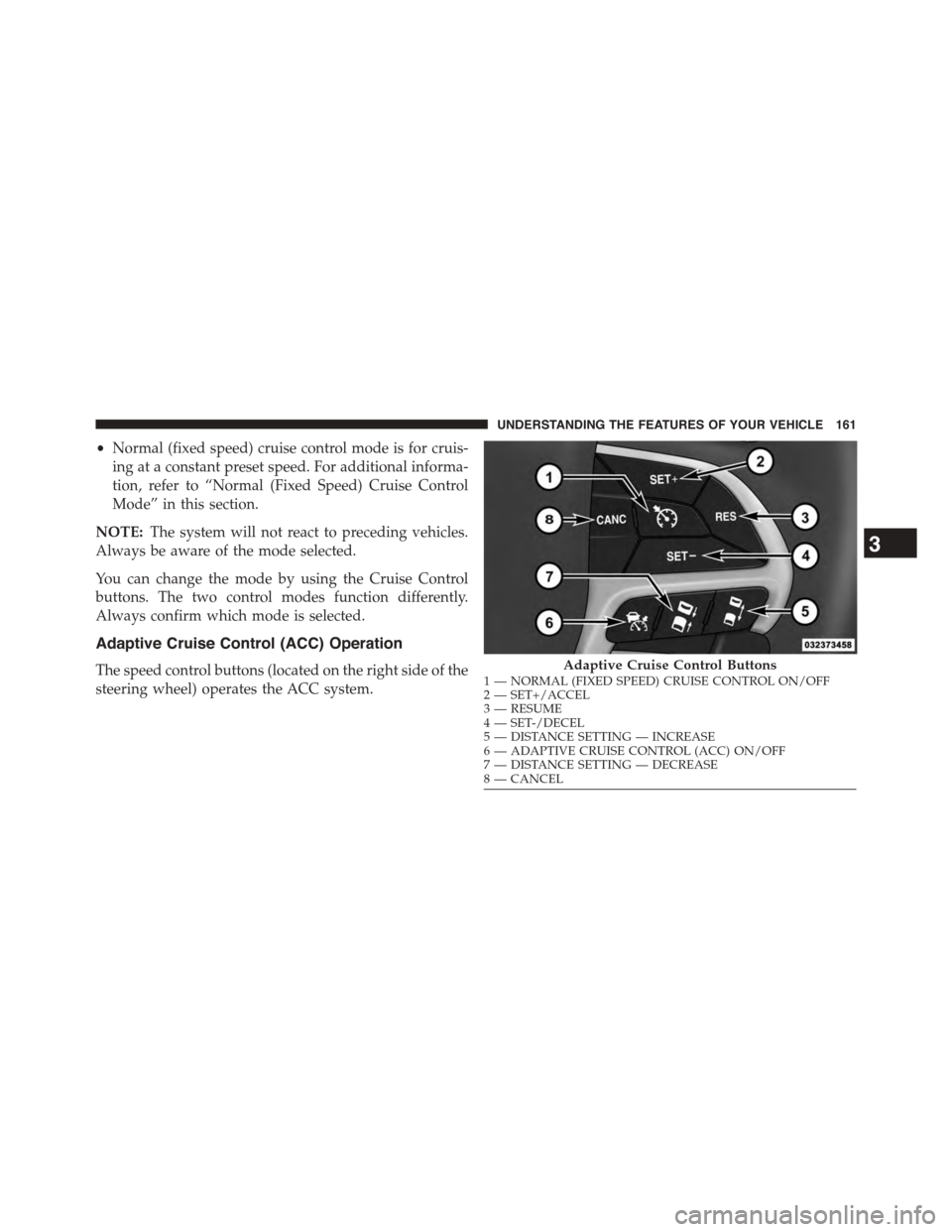
The speed control buttons (located on the right side of the
steering wheel) operates the ACC system.
Adaptive Cruise Control Buttons1—NORMAL(FIXEDSPEED)CRUISECONTROLON/OFF2—SET+/ACCEL3—RESUME4—SET-/DECEL5—DISTANCESETTING—INCREASE6—ADAPTIVECRUISECONTROL(ACC)ON/OFF7—DISTANCESETTING—DECREASE8—CANCEL
3
UNDERSTANDING THE FEATURES OF YOUR VEHICLE 161
Page 169 of 603
Metric Speed (km/h)
•Pressing the SET-button once will result in a 1 km/h
decrease in set speed. Each subsequent tap of the
button results in a decrease of 1 km/h.
•If the button is continually pressed, the set speed will
continue to decrease in 10 km/h increments until the
button is released. The decrease in set speed is re-
flected in the DID.
NOTE:
•When you override and push the SET+button or SET
-buttons, the new Set Speed will be the current speed
of the vehicle.
•When you use the SET-button to decelerate, if the
engine’s braking power does not slow the vehicle
sufficiently to reach the set speed, the brake system
will automatically slow the vehicle.
•The ACC system applies the brake down to 15 mph
(24 km/h) when following a target vehicle.
•The ACC system maintains set speed when driving up
hill and down hill. However, a slight speed change on
moderate hills is normal. In addition, downshifting
may occur while climbing uphill or descending down-
hill. This is normal operation and necessary to main-
tain set speed. When driving up hill and down hill, the
ACC system will cancel if the braking temperature
exceeds normal range (overheated).
Setting The Following Distance In ACC
The specified following distance for ACC can be set by
varying the distance setting between four bars (longest),
three bars (long), two bars (medium) and one bar (short).
Using this distance setting and the vehicle speed, ACC
calculates and sets the distance to the vehicle ahead. This
distance setting displays in the DID.
3
UNDERSTANDING THE FEATURES OF YOUR VEHICLE 167
Page 201 of 603
GARAGE DOOR OPENER — IF EQUIPPED
HomeLink® replaces up to three hand-held transmitters
that operate devices such as garage door openers, motor-
ized gates, lighting or home security systems. The
HomeLink® unit is powered by your vehicles 12 Volt
battery.
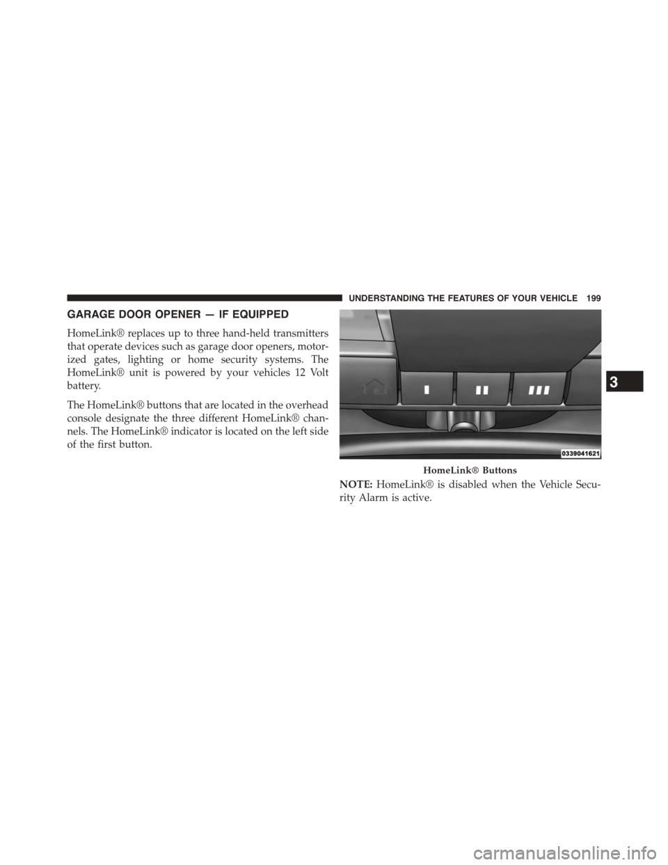
The HomeLink® buttons that are located in the overhead
console designate the three different HomeLink® chan-
nels. The HomeLink® indicator is located on the left side
of the first button.
NOTE:HomeLink® is disabled when the Vehicle Secu-
rity Alarm is active.
HomeLink® Buttons
3
UNDERSTANDING THE FEATURES OF YOUR VEHICLE 199