fuel cap DODGE CHALLENGER 2015 3.G Owners Manual
[x] Cancel search | Manufacturer: DODGE, Model Year: 2015, Model line: CHALLENGER, Model: DODGE CHALLENGER 2015 3.GPages: 603, PDF Size: 14.97 MB
Page 226 of 603
INSTRUMENT CLUSTER DESCRIPTIONS
1. Tachometer
The red segments indicate the maximum permissible
engine revolutions per minute (RPM x 1000) for each gear
range. Ease up on the accelerator before reaching the red
area.
2. Malfunction Indicator Light (MIL)
The Malfunction Indicator Light (MIL) is part of
an onboard diagnostic system called OBD. The
OBD system monitors engine and automatic
transmission control systems. The MIL will turn on when
the ignition is in the ON/RUN position before engine
start. If the MIL does not come on when turning the key
from OFF to ON/RUN, have the condition checked
promptly.
Certain conditions, such as a loose or missing gas cap,
poor fuel quality, etc., may illuminate the MIL after
engine start. The vehicle should be serviced if the MIL
stays on through several of your typical driving cycles. In
most situations, the vehicle will drive normally and will
not require towing.
CAUTION!
Prolonged driving with the Malfunction Indicator
Light (MIL) on could cause damage to the engine
control system. It also could affect fuel economy and
driveability. If the MIL is flashing, severe catalytic
converter damage and power loss will soon occur.
Immediate service is required.
WARNING!
A malfunctioning catalytic converter, as referenced
above, can reach higher temperatures than in normal
(Continued)
224 UNDERSTANDING YOUR INSTRUMENT PANEL
Page 256 of 603
Units
After pressing the “Units” button on the touchscreen the
following settings will be available:
•Units
When in this display, you may select each unit of measure
independently displayed in the Driver Information Dis-
play (DID), and navigation system (if equipped). The
following selectable units of measure are listed below:
•Speed
Select from: “MPH” or “km/h.”
•Distance
Select from: “mi” or “km.”
•Fuel Consumption
Select from: “MPG” (US), “MPG” (UK), “L/100 km” or
“km/L.”
•Capacity
Select from: “gal” (US), “gal” (UK), or “L.”
•Pressure
Select from: “psi,” “kPa,” or “bar.”
•Temperature
Select from: “°C,” or “°F.”
•Power
Select from: “HP” (US), “HP” (UK), and “kW.”
•Torque
Select from: “lb-ft” or “Nm.”
•After the desired setting has been selected, press the
back arrow/Done button on the touchscreen to return
to the previous menu.
254 UNDERSTANDING YOUR INSTRUMENT PANEL
Page 273 of 603
•Navigation Turn-By-Turn In Cluster — If Equipped
When this feature is selected, the turn-by-turn directions
will appear in the display as the vehicle approaches a
designated turn within a programmed route. To make
your selection, press the “Navigation Turn-By-Turn In
Cluster” button on the touchscreen, until a check-mark
appears next to the setting, showing that setting has been
selected. Press the back arrow button on the touchscreen
to return to the previous menu.
Units
After pressing the “Units” button on the touchscreen the
following settings will be available:
•Units
When in this display, you may select each unit of measure
independently displayed in the Driver Information Dis-
play (DID), and navigation system (if equipped). The
following selectable units of measure are listed below:
•Speed
Select from: “MPH” or “km/h.”
•Distance
Select from: “mi” or “km.”
•Fuel Consumption
Select from: “MPG” (US), “MPG” (UK), “L/100 km” or
“km/L.”
•Capacity
Select from: “gal” (US), “gal” (UK), or “L.”
•Pressure
Select from: “psi,” “kPa,” or “bar.”
•Temperature
Select from: “°C,” or “°F.”
4
UNDERSTANDING YOUR INSTRUMENT PANEL 271
Page 348 of 603
▫6.4L Engine..........................426
▫Reformulated Gasoline.................427
▫Gasoline/Oxygenate Blends..............427
▫E-85 Usage In Non-Flex Fuel Vehicles.......428
▫MMT In Gasoline.....................428
▫Materials Added To Fuel................429
▫Fuel System Cautions...................429
▫Carbon Monoxide Warnings.............430
!ADDING FUEL........................431
▫Fuel Filler Cap (Gas Cap)...............431
▫Loose Fuel Filler Cap Message............433
!VEHICLE LOADING....................433
▫Vehicle Certification Label...............433
▫Gross Vehicle Weight Rating (GVWR).......434
▫Gross Axle Weight Rating (GAWR).........434
▫Overloading.........................434
▫Loading............................435
!TRAILER TOWING.....................435
▫Common Towing Definitions.............436
▫Trailer Hitch Classification...............439
▫Trailer Towing Weights (Maximum Trailer Weight
Ratings)............................440
▫Trailer And Tongue Weight..............440
▫Towing Requirements..................441
▫Towing Tips.........................446
!RECREATIONAL TOWING (BEHIND
MOTORHOME, ETC.)...................448
▫Towing This Vehicle Behind Another Vehicle . .448
346 STARTING AND OPERATING
Page 356 of 603
Clearing A Flooded Engine (Using ENGINE
START/STOP Button) — Manual Transmission
Only
If the engine fails to start after you have followed the
“Normal Starting” or “Extreme Cold Weather#proce-
dures, it may be flooded. To clear any excess fuel, press
and hold the clutch pedal, push the accelerator pedal all
the way to the floor and hold it, then press and hold the
ENGINE START/STOP button for no more than 15
seconds. Release the accelerator pedal and the clutch
pedal, wait 10 to 15 seconds, then repeat the “Normal
Starting” procedure.
After Starting
The idle speed is controlled automatically and it will
decrease as the engine warms up.
ENGINE BLOCK HEATER — IF EQUIPPED
The engine block heater warms the engine, and permits
quicker starts in cold weather. Connect the cord to a
standard 110-115 Volt AC electrical outlet with a
grounded, three-wire extension cord.
The engine block heater must be plugged in at least one
hour to have an adequate warming effect on the engine.
The engine block heater cord is routed under the hood on
the driver side of the vehicle. It has a removable cap that
is located near the air box.
WARNING!
Remember to disconnect the engine block heater
cord before driving. Damage to the 110-115 Volt
electrical cord could cause electrocution.
354 STARTING AND OPERATING
Page 433 of 603
WARNING!(Continued)
•Guard against carbon monoxide with proper main-
tenance. Have the exhaust system inspected every
time the vehicle is raised. Have any abnormal
conditions repaired promptly. Until repaired, drive
with all side windows fully open.
•Keep the trunk closed when driving your vehicle to
prevent carbon monoxide and other poisonous ex-
haust gases from entering the vehicle.
ADDING FUEL
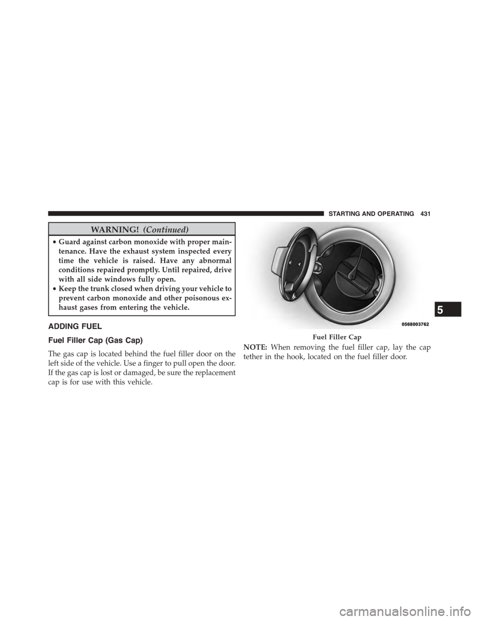
Fuel Filler Cap (Gas Cap)
The gas cap is located behind the fuel filler door on the
left side of the vehicle. Use a finger to pull open the door.
If the gas cap is lost or damaged, be sure the replacement
cap is for use with this vehicle.
NOTE:When removing the fuel filler cap, lay the cap
tether in the hook, located on the fuel filler door.
Fuel Filler Cap
5
STARTING AND OPERATING 431
Page 434 of 603
CAUTION!
•Damage to the fuel system or emissions control
system could result from using an improper fuel
tank filler tube cap (gas cap).
•A poorly fitting gas cap could let impurities into
the fuel system.
•A poorly fitting gas cap may cause the “Malfunc-
tion Indicator Light (MIL)” to turn on.
•To avoid fuel spillage and overfilling, do not “top
off” the fuel tank after filling. When the fuel
nozzle “clicks” or shuts off, the fuel tank is full.
WARNING!
•Never have any smoking materials lit in or near the
vehicle when the gas cap is removed or the tank is
being filled.
(Continued)
WARNING!(Continued)
•Never add fuel to the vehicle when the engine is
running.
•A fire may result if gasoline is pumped into a
portable container that is inside of a vehicle. You
could be burned. Always place gas containers on
the ground while filling.
NOTE:
•When the fuel nozzle “clicks” or shuts off, the fuel tank
is full.
•Tighten the gas cap until you hear a “clicking” sound.
This is an indication that the gas cap is tightened
properly. The MIL in the instrument cluster may turn
on if the gas cap is not secured properly. Make sure
that the gas cap is tightened each time the vehicle is
refueled.
432 STARTING AND OPERATING
Page 435 of 603
Loose Fuel Filler Cap Message
If the vehicle diagnostic system determines that the fuel
filler cap is loose, improperly installed, or damaged, a
”gASCAP” message will display in the odometer or a
“Check Gascap” message will display in the Driver
Information Display (DID). If this occurs, tighten the fuel
filler cap properly and press the TRIP ODOMETER
button to turn off the message. If the problem continues,
the message will appear the next time the vehicle is
started.
A loose, improperly installed, or damaged fuel filler cap
may also turn on the MIL. Refer to “Onboard Diagnostic
System” in “Maintaining Your Vehicle” for further infor-
mation.
VEHICLE LOADING
The load carrying capacity of your vehicle is shown on
the “Vehicle Certification Label”. This information
should be used for passenger and luggage loading as
indicated.
Do not exceed the specified Gross Vehicle Weight Rating
(GVWR) or the Gross Axle Weight Rating (GAWR).
Vehicle Certification Label
Your vehicle has a Vehicle Certification Label affixed to
the drivers side B-Pillar or the rear of the driver ’s door.
The label contains the following information:
•Name of manufacturer
•Month and year of manufacture
•Gross Vehicle Weight Rating (GVWR)
•Gross Axle Weight Rating (GAWR) front
5
STARTING AND OPERATING 433
Page 489 of 603
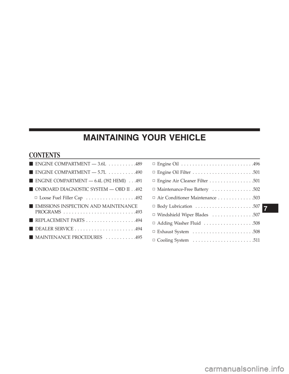
MAINTAINING YOUR VEHICLE
CONTENTS
!ENGINE COMPARTMENT — 3.6L..........489
!ENGINE COMPARTMENT — 5.7L..........490
!ENGINE COMPARTMENT — 6.4L (392 HEMI) . . .491
!ONBOARD DIAGNOSTIC SYSTEM — OBD II . .492
▫Loose Fuel Filler Cap..................492
!EMISSIONS INSPECTION AND MAINTENANCE
PROGRAMS..........................493
!REPLACEMENT PARTS..................494
!DEALER SERVICE......................494
!MAINTENANCE PROCEDURES...........495
▫Engine Oil..........................496
▫Engine Oil Filter......................501
▫Engine Air Cleaner Filter................501
▫Maintenance-Free Battery...............502
▫Air Conditioner Maintenance.............503
▫Body Lubrication.....................507
▫Windshield Wiper Blades...............507
▫Adding Washer Fluid..................508
▫Exhaust System......................508
▫Cooling System......................511
7
Page 494 of 603
ONBOARD DIAGNOSTIC SYSTEM — OBD II
Your vehicle is equipped with a sophisticated onboard
diagnostic system called OBD II. This system monitors
the performance of the emissions, engine, and automatic
transmission control systems. When these systems are
operating properly, your vehicle will provide excellent
performance and fuel economy, as well as engine emis-
sions well within current government regulations.
If any of these systems require service, the OBD II system
will turn on the “Malfunction Indicator Light” (MIL). It
will also store diagnostic codes and other information to
assist your service technician in making repairs. Al-
though your vehicle will usually be drivable and not
need towing, see your authorized dealer for service as
soon as possible.
CAUTION!
•Prolonged driving with the MIL on could cause
further damage to the emission control system. It
could also affect fuel economy and driveability.
The vehicle must be serviced before any emissions
tests can be performed.
•If the MIL is flashing while the engine is running,
severe catalytic converter damage and power loss
will soon occur. Immediate service is required.
Loose Fuel Filler Cap
If the vehicle diagnostic system determines that the fuel
filler cap is loose, improperly installed, or damaged, a
”gASCAP” message will display in the odometer or a
“Check Gascap” message will display in the Driver
Information Display (DID). If this occurs, tighten the fuel
filler cap properly and press the Trip Odometer button to
492 MAINTAINING YOUR VEHICLE