length DODGE CHALLENGER 2015 3.G Owners Manual
[x] Cancel search | Manufacturer: DODGE, Model Year: 2015, Model line: CHALLENGER, Model: DODGE CHALLENGER 2015 3.GPages: 603, PDF Size: 14.97 MB
Page 119 of 603
Automatic Transmission Vehicles
The BSM system sensors operate when the vehicle is in
any forward gear or REVERSE and enters stand-by mode
when the vehicle is in PARK.
Manual Transmission Vehicles
The BSM system sensors operate when the vehicle is in
any gear and enters stand-by mode when the Park Brake
is engaged, the vehicle is not in REVERSE, and the
vehicle is stationary.
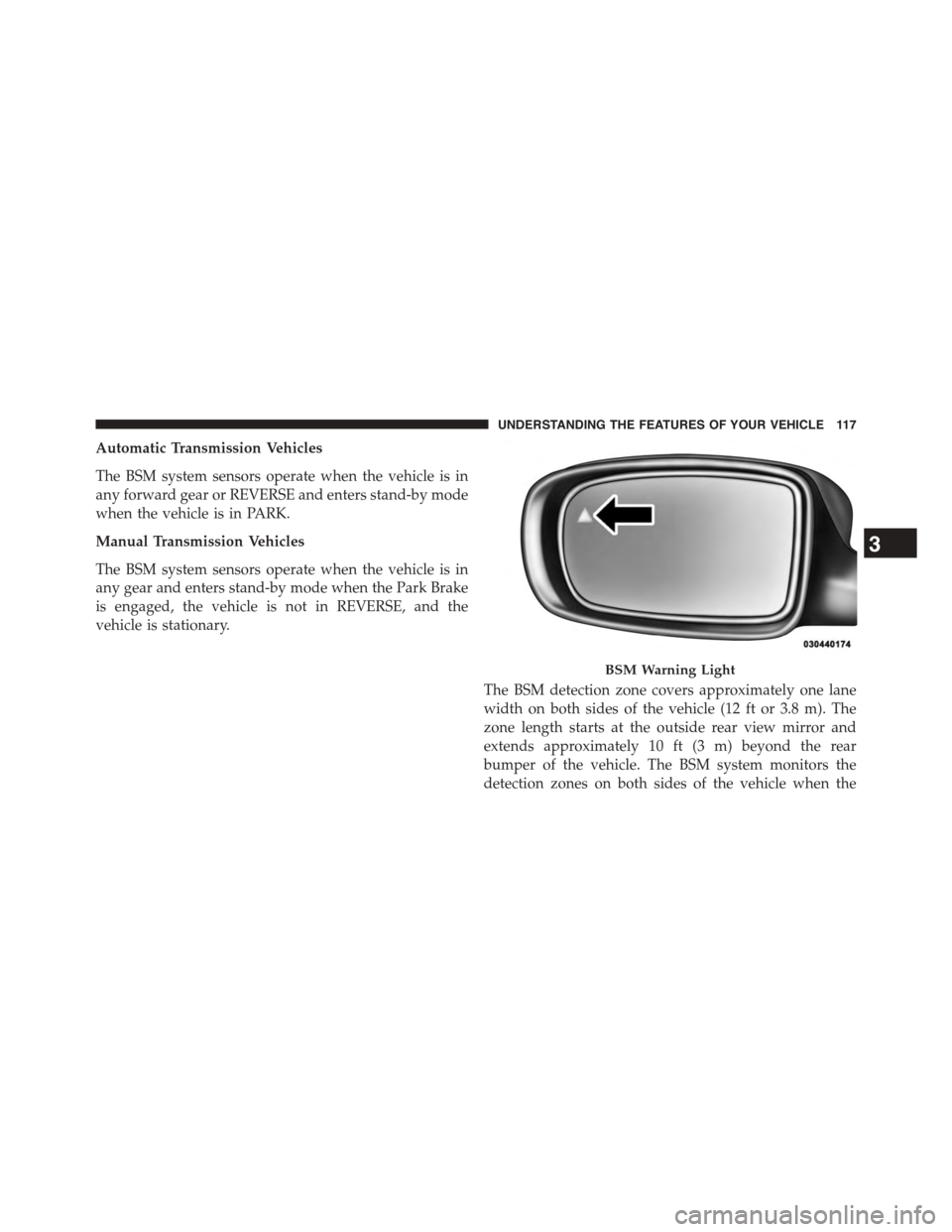
The BSM detection zone covers approximately one lane
width on both sides of the vehicle (12 ft or 3.8 m). The
zone length starts at the outside rear view mirror and
extends approximately 10 ft (3 m) beyond the rear
bumper of the vehicle. The BSM system monitors the
detection zones on both sides of the vehicle when the
BSM Warning Light
3
UNDERSTANDING THE FEATURES OF YOUR VEHICLE 117
Page 153 of 603
The Rain Sensing system has protection features for the
wiper blades and arms, and will not operate under the
following conditions:
•Low Ambient Temperature— When the ignition is
first turned ON, the Rain Sensing system will not
operate until the wiper switch is moved, vehicle speed
is greater than 0 mph (0 km/h), or the outside tem-
perature is greater than 32°F (0°C).
•Transmission In NEUTRAL Position— When the
ignition is ON, and the transmission is in the NEU-
TRAL position, the Rain Sensing system will not
operate until the wiper switch is moved, vehicle speed
is greater than 5 mph (8 km/h), or the shift lever is
moved out of the NEUTRAL position.
NOTE:Rain Sensing can be turned on and off using the
Uconnect® System, refer to “Uconnect® Settings” in
“Understanding Your Instrument Panel” for further in-
formation.
TILT/TELESCOPING STEERING COLUMN
This feature allows you to tilt the steering column
upward or downward. It also allows you to lengthen or
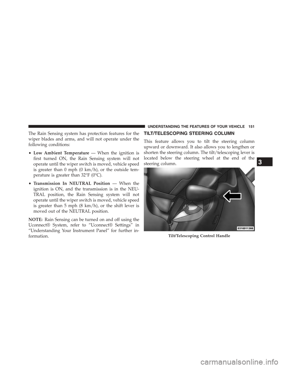
shorten the steering column. The tilt/telescoping lever is
located below the steering wheel at the end of the
steering column.
Tilt/Telescoping Control Handle
3
UNDERSTANDING THE FEATURES OF YOUR VEHICLE 151
Page 154 of 603
To unlock the steering column, pull the lever downward.
To tilt the steering column, move the steering wheel
upward or downward as desired. To lengthen or shorten
the steering column, pull the steering wheel outward or
push it inward as desired. To lock the steering column in
position, push the lever upward until fully engaged.
WARNING!
Do not adjust the steering column while driving.
Adjusting the steering column while driving or driv-
ing with the steering column unlocked, could cause
the driver to lose control of the vehicle. Failure to
follow this warning may result in serious injury or
death.
POWER TILT/TELESCOPING STEERING COLUMN
— IF EQUIPPED
This feature allows you to tilt the steering column
upward or downward. It also allows you to lengthen or
shorten the steering column. The power tilt/telescoping
steering column lever is located below the multifunction
lever on the steering column.
152 UNDERSTANDING THE FEATURES OF YOUR VEHICLE
Page 155 of 603
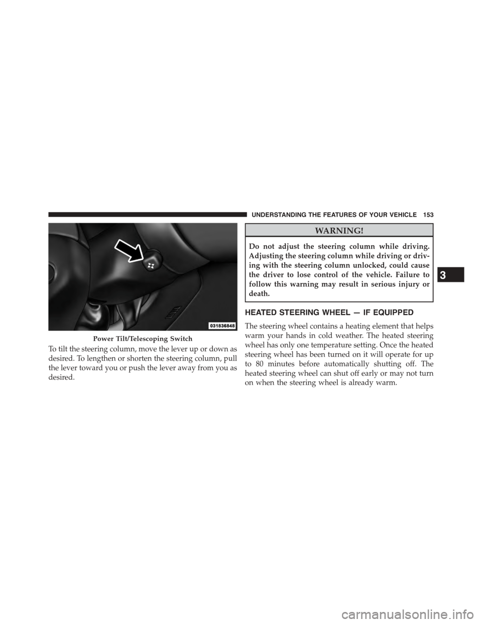
To tilt the steering column, move the lever up or down as
desired. To lengthen or shorten the steering column, pull
the lever toward you or push the lever away from you as
desired.
WARNING!
Do not adjust the steering column while driving.
Adjusting the steering column while driving or driv-
ing with the steering column unlocked, could cause
the driver to lose control of the vehicle. Failure to
follow this warning may result in serious injury or
death.
HEATED STEERING WHEEL — IF EQUIPPED
The steering wheel contains a heating element that helps
warm your hands in cold weather. The heated steering
wheel has only one temperature setting. Once the heated
steering wheel has been turned on it will operate for up
to 80 minutes before automatically shutting off. The
heated steering wheel can shut off early or may not turn
on when the steering wheel is already warm.
Power Tilt/Telescoping Switch
3
UNDERSTANDING THE FEATURES OF YOUR VEHICLE 153
Page 216 of 603
WARNING!
To avoid serious injury or death:
•Only devices designed for use in this type of outlet
should be inserted into any 12 Volt outlet.
•Do not touch with wet hands.
•Close the lid when not in use and while driving the
vehicle.
•If this outlet is mishandled, it may cause an electric
shock and failure.
CAUTION!
•Many accessories that can be plugged in draw
power from the vehicle’s battery, even when not in
use (i.e., cellular phones, etc.). Eventually, if
plugged in long enough, the vehicle’s battery will
discharge sufficiently to degrade battery life and/or
prevent the engine from starting.
•Accessories that draw higher power (i.e., coolers,
vacuum cleaners, lights, etc.), will degrade the
battery even more quickly. Only use these intermit-
tently and with greater caution.
•After the use of high power draw accessories, or
long periods of the vehicle not being started (with
accessories still plugged in), the vehicle must be
driven a sufficient length of time to allow the
alternator to recharge the vehicle’s battery.
(Continued)
214 UNDERSTANDING THE FEATURES OF YOUR VEHICLE
Page 257 of 603
Voice
•Voice Response Length
When in this display, you may change the Voice Re-
sponse Length settings. To change mode status, press and
release the “Brief” or “Long” button on the touchscreen.
Press the back arrow/Done button on the touchscreen to
return to the previous menu.
•Show Command List
When in this display, you may change the Show Com-
mand List settings. To change the mode status, press and
release the “Always,” “With Help,” or “Never” button on
the touchscreen. Press the back arrow/Done button on
the touchscreen to return to the previous menu.
Clock & Date
After pressing the “Clock & Date” button on the touch-
screen the following settings will be available:
•Set Time
When in this display, you may set the time and format
manually. Press the “Set Time” button then choose from
a 12 hour or 24 hour format. Press the corresponding
arrow above and below the current time to adjust, then
select “AM” or “PM.” Press the back arrow/Done button
on the touchscreen to return to the previous menu.
•Show Time Status
When in this display, you may turn on or shut off the
digital clock in the status bar. To change the Show Time
Status setting press the “Show Time Status” button on the
touchscreen and select from “ON” or “OFF.” Press the
back arrow/Done button on the touchscreen to return to
the previous menu.
•Set Date
When in this display, you may set the date manually.
Press the “Set Date” button on the touchscreen then press
4
UNDERSTANDING YOUR INSTRUMENT PANEL 255
Page 274 of 603
•Power
Select from: “HP” (US), “HP” (UK), and “kW.”
•Torque
Select from: “lb-ft” or “Nm.”
•After the desired setting has been selected, press the
back arrow button on the touchscreen to return to the
previous menu.
Voice
•Voice Response Length
When in this display, you may change the Voice Re-
sponse Length settings. To change the Voice Response
Length, press the “Brief” or “Detailed” button on the
touchscreen until a check-mark appears next to the
setting, showing that setting has been selected. Press the
back arrow button on the touchscreen to return to the
previous menu.
•Show Command List
When in this display, you may change the Show Com-
mand List settings. To change the Show Command List
settings, press the “Always,” “With Help” or “Never”
button on the touchscreen until a check-mark appears
next to the setting, showing that setting has been se-
lected. Press the back arrow button on the touchscreen to
return to the previous menu.
Clock
After pressing the “Clock” button on the touchscreen the
following settings will be available:
•Sync Time With GPS
This feature will allow you to automatically have the
radio set the time. To change the Sync Time setting, press
the “Sync time with GPS” button on the touchscreen until
a check-mark appears next to the setting, showing that
272 UNDERSTANDING YOUR INSTRUMENT PANEL