ESP DODGE CHALLENGER 2015 3.G User Guide
[x] Cancel search | Manufacturer: DODGE, Model Year: 2015, Model line: CHALLENGER, Model: DODGE CHALLENGER 2015 3.GPages: 220, PDF Size: 30.96 MB
Page 6 of 220
VEHICLES SOLD IN CANADA
With respect to any vehicles sold in Canada, the name Chrysler Group LLC shall be
deemed to be deleted and the name Chrysler Canada Inc. used in substitution (excluding
legal lines).
WARNING!
•Pedalsthatcannotmovefreelycancauselossofvehiclecontrolandincreasethe
risk of serious personal injury.
•Alwaysmakesurethatobjectscannotfallintothedriverfootwellwhilethevehicle
is moving. Objects can become trapped under the brake pedal and accelerator
pedal causing a loss of vehicle control.
•Failuretoproperlyfollowfloormatinstallationormountingcancauseinterference
with the brake pedal and accelerator pedal operation causing loss of control of the
vehicle.
•Neverleavechildrenaloneinavehicle,orwithaccesstoanunlockedvehicle.
Allowing children to be in a vehicle unattended is dangerous for a number of
reasons. A child or others could be seriously or fatally injured. Children should be
warned not to touch the parking brake, brake pedal or the shift lever/transmission
gear selector.
•Donotleavethekeyfobinornearthevehicle,orinalocationaccessibletochildren,
and do not leave the ignition of a vehicle equipped with Keyless Enter-N-Go in the
ACC or ON/RUN mode. A child could operate power windows, other controls, or
move the vehicle.
•Neverusethe“PARK”positionasasubstitutefortheparkingbrake.Alwaysapply
the parking brake fully when parked to guard against vehicle movement and
possible injury or damage.
•RefertoyourOwner'sManualontheDVDforfurtherdetails.
INTRODUCTION/WELCOME
4
Page 20 of 220
SUPPLEMENTAL RESTRAINT SYSTEM (SRS) — AIR BAGS
Air Bag System Components
Yo u r v e h i c l e m a y b e e q u i p p e d w i t h t h e f o l l o w i n g a i r b a g s y s t e m c o m p o n e n t s :
•OccupantRestraintController(ORC)
•AirBagWarningLight
•SteeringWheelandColumn
•InstrumentPanel
•KneeImpactBolsters
•AdvancedFrontAirBags
•SupplementalSideAirBags
•FrontandSideImpactSensors
•SeatBeltPretenioners
•SeatBeltBuckleSwitch
•SeatTrackPositionSensors
Advanced Front Air Bags
•ThisvehiclehasAdvancedFrontAirBagsforboththedriverandfrontpassengerasa
supplement to the seat belt restraint systems. The Advanced Front Air Bags will not
deploy in every type of collision.
•AdvancedFrontAirBagsaredesignedtoprovideadditionalprotectionbysupplement-
ing the seat belts. Advanced Front Air Bags are not expected to reduce the risk of injury
in rear, side, or rollover collisions.
•TheAdvancedFrontAirBagswillnotdeployinallfrontalcollisions,includingsome
that may produce substantial vehicle damage — for example, some pole collisions,
truck underrides, and angle offset collisions.
•Ontheotherhand,dependingonthetypeandlocationofimpact,AdvancedFrontAir
Bags may deploy in crashes with little vehicle front-end damage but that produce a
severe initial deceleration.
•Becauseairbagsensorsmeasurevehicledecelerationovertime,vehiclespeedand
damage by themselves are not good indicators of whether or not an air bag should have
deployed.
•Seatbeltsarenecessaryforyourprotectioninallcollisions,andalsoareneededtohelp
keep you in position, away from an inflating air bag.
•Theairbagsmustbereadytoinflateforyourprotectioninacollision.TheOccupant
Restraint Controller (ORC) monitors the internal circuits and interconnecting wiring
associated with air bag system electrical components.
GETTING STARTED
18
Page 31 of 220
HEATED/VENTILATED SEATS
Front Heated Seats
The front heated seats control buttons are located within the climate or controls screen of
the touchscreen.
•Presstheheatedseatbuttononce to turn the High setting On.
•PresstheheatedseatbuttonasecondtimetoturntheLowsettingOn.
•PresstheheatedseatbuttonathirdtimetoturntheheatingelementsOff.
If the High-level setting is selected, the system will automatically switch to Low-level after
approximately 60 minutes. The Low-level setting will turn Off automatically after approxi-
mately 45 minutes.
NOTE:
Vehicle Equipped With Remote Start
On models that are equipped with remote start, this feature can be programmed to come
on during a remote start through the Uconnect®system. Refer to “Uconnect®Settings”
in “Understanding Your Instrument Panel” in the Owner's Manual on the DVD.
WARNING!
•Personswhoareunabletofeelpaintotheskinbecauseofadvancedage,chronic
illness, diabetes, spinal cord injury, medication, alcohol use, exhaustion or other
physical conditions must exercise care when using the seat heater. It may cause
burns even at low temperatures, especially if used for long periods of time.
•Donotplaceanythingontheseatthatinsulatesagainstheat,suchasablanketor
cushion. This may cause the seat heater to overheat. Sitting in a seat that has been
overheated could cause serious burns due to the increased surface temperature of
the seat.
Front Ventilated Seats
Located in the seat cushion and seatback are small fans that draw the air from the
passenger compartment and pull air through fine perforations in the seat cover to help
keep the driver and front passenger cooler in higher ambient temperatures.
There are two ventilated seat control buttons located in the touchscreen that allow the
driver and passenger to operate the seats independently.
The ventilated seat buttons are used to control the speed of the fans located in the seat.
GETTING STARTED
29
Page 32 of 220
To o p e r a t e t h e s y s t e m , p r e s s t h e “ C o n t r o l s ” b u t t o n o n t o u c h s c r e e n l o c a t e d o n t h e b o t t o m
of the Uconnect®display.
•Presstheventilatedseatbuttononce to choose HIGH.
•PresstheventilatedseatbuttonasecondtimetochooseLOW.
•PresstheventilatedseatbuttonathirdtimetoturntheventilatedseatOFF.
NOTE:
Vehicle Equipped With Remote Start
On models that are equipped with remote start, this feature can be programmed to come
on during a remote start through the Uconnect®system. Refer to “Uconnect®Settings”
in “Understanding Your Instrument Panel” in the Owner's Manual on the DVD.
HEATED STEERING WHEEL
The steering wheel contains a heating element that heats the steering wheel to one
temperature setting.
The heated steering wheel control button is located within the Uconnect®system. You can
gain access to the control buttons through the climate screen or the controls screen.
•Presstheheatedsteeringwheelbuttononce to turn the heating element ON.
•Presstheheatedsteeringwheelbuttonasecondtimetoturntheheatingelement
OFF.
Once the heated steering wheel has been turned on, it will operate for up to 80 minutes
before automatically shutting off. The heated steering wheel can shut off early or may not
turn on when the steering wheel is already warm.
NOTE:
Vehicle Equipped With Remote Start
On models that are equipped with remote start, this feature can be programmed to come
on during a remote start through the Uconnect®system. Refer to “Uconnect®Settings”
in “Understanding Your Instrument Panel” in the Owner's Manual on the DVD.
WARNING!
•Personswhoareunabletofeelpaintotheskinbecauseofadvancedage,chronic
illness, diabetes, spinal cord injury, medication, alcohol use, exhaustion, or other
physical conditions must exercise care when using the steering wheel heater. It may
cause burns even at low temperatures, especially if used for long periods.
•Donotplaceanythingonthesteeringwheelthatinsulatesagainstheat,suchasa
blanket or steering wheel covers of any type and material. This may cause the
steering wheel heater to overheat.
GETTING STARTED
30
Page 35 of 220
ENGINE BREAK-IN RECOMMENDATIONS
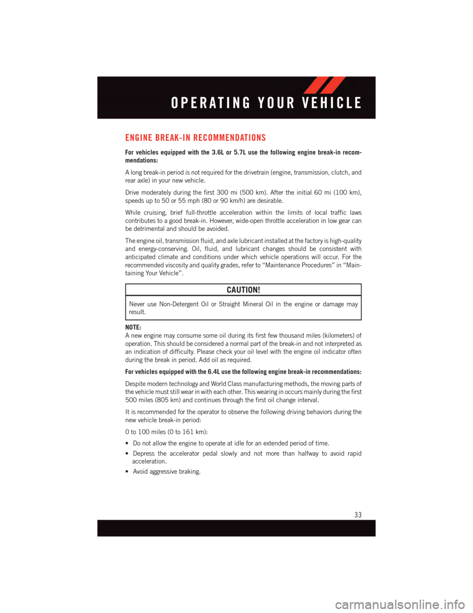
For vehicles equipped with the 3.6L or 5.7L use the following engine break-in recom-
mendations:
Alongbreak-inperiodisnotrequiredforthedrivetrain(engine,transmission,clutch,and
rear axle) in your new vehicle.
Drive moderately during the first 300 mi (500 km). After the initial 60 mi (100 km),
speeds up to 50 or 55 mph (80 or 90 km/h) are desirable.
While cruising, brief full-throttle acceleration within the limits of local traffic laws
contributes to a good break-in. However, wide-open throttle acceleration in low gear can
be detrimental and should be avoided.
The engine oil, transmission fluid, and axle lubricant installed at the factory is high-quality
and energy-conserving. Oil, fluid, and lubricant changes should be consistent with
anticipated climate and conditions under which vehicle operations will occur. For the
recommended viscosity and quality grades, refer to “Maintenance Procedures” in “Main-
taining Your Vehicle”.
CAUTION!
Never use Non-Detergent Oil or Straight Mineral Oil in the engine or damage may
result.
NOTE:
Anewenginemayconsumesomeoilduringitsfirstfewthousandmiles(kilometers)of
operation. This should be considered a normal part of the break-in and not interpreted as
an indication of difficulty. Please check your oil level with the engine oil indicator often
during the break in period. Add oil as required.
For vehicles equipped with the 6.4L use the following engine break-in recommendations:
Despite modern technology and World Class manufacturing methods, the moving parts of
the vehicle must still wear in with each other. This wearing in occurs mainly during the first
500 miles (805 km) and continues through the first oil change interval.
It is recommended for the operator to observe the following driving behaviors during the
new vehicle break-in period:
0to100miles(0to161km):
•Donotallowtheenginetooperateatidleforanextendedperiodoftime.
•Depresstheacceleratorpedalslowlyandnotmorethanhalfwaytoavoidrapid
acceleration.
•Avoidaggressivebraking.
OPERATING YOUR VEHICLE
33
Page 36 of 220
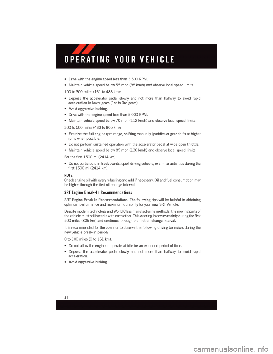
•Drivewiththeenginespeedlessthan3,500RPM.
•Maintainvehiclespeedbelow55mph(88km/h)andobservelocalspeedlimits.
100 to 300 miles (161 to 483 km):
•Depresstheacceleratorpedalslowlyandnotmorethanhalfwaytoavoidrapid
acceleration in lower gears (1st to 3rd gears).
•Avoidaggressivebraking.
•Drivewiththeenginespeedlessthan5,000RPM.
•Maintainvehiclespeedbelow70mph(112km/h)andobservelocalspeedlimits.
300 to 500 miles (483 to 805 km):
•Exercisethefullenginerpmrange,shiftingmanually(paddlesorgearshift)athigher
rpms when possible.
•Donotperformsustainedoperationwiththeacceleratorpedalatwideopenthrottle.
•Maintainvehiclespeedbelow85mph(136km/h)andobservelocalspeedlimits.
For the first 1500 mi (2414 km):
•Donotparticipateintrackevents,sportdrivingschools,orsimilaractivitiesduringthe
first 1500 mi (2414 km).
NOTE:
Check engine oil with every refueling and add if necessary. Oil and fuel consumption may
be higher through the first oil change interval.
SRT Engine Break-In Recommendations
SRT Engine Break-In Recommendations: The following tips will be helpful in obtaining
optimum performance and maximum durability for your new SRT Vehicle.
Despite modern technology and World Class manufacturing methods, the moving parts of
the vehicle must still wear in with each other. This wearing in occurs mainly during the first
500 miles (805 km) and continues through the first oil change interval.
It is recommended for the operator to observe the following driving behaviors during the
new vehicle break-in period:
0to100miles(0to161km):
•Donotallowtheenginetooperateatidleforanextendedperiodoftime.
•Depresstheacceleratorpedalslowlyandnotmorethanhalfwaytoavoidrapid
acceleration.
•Avoidaggressivebraking.
OPERATING YOUR VEHICLE
34
Page 37 of 220
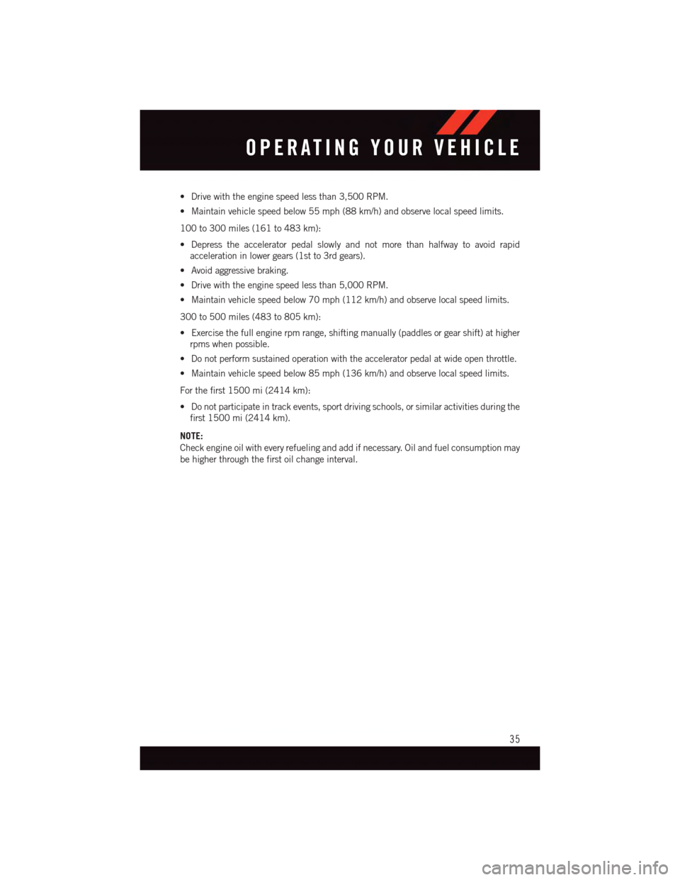
•Drivewiththeenginespeedlessthan3,500RPM.
•Maintainvehiclespeedbelow55mph(88km/h)andobservelocalspeedlimits.
100 to 300 miles (161 to 483 km):
•Depresstheacceleratorpedalslowlyandnotmorethanhalfwaytoavoidrapid
acceleration in lower gears (1st to 3rd gears).
•Avoidaggressivebraking.
•Drivewiththeenginespeedlessthan5,000RPM.
•Maintainvehiclespeedbelow70mph(112km/h)andobservelocalspeedlimits.
300 to 500 miles (483 to 805 km):
•Exercisethefullenginerpmrange,shiftingmanually(paddlesorgearshift)athigher
rpms when possible.
•Donotperformsustainedoperationwiththeacceleratorpedalatwideopenthrottle.
•Maintainvehiclespeedbelow85mph(136km/h)andobservelocalspeedlimits.
For the first 1500 mi (2414 km):
•Donotparticipateintrackevents,sportdrivingschools,orsimilaractivitiesduringthe
first 1500 mi (2414 km).
NOTE:
Check engine oil with every refueling and add if necessary. Oil and fuel consumption may
be higher through the first oil change interval.
OPERATING YOUR VEHICLE
35
Page 40 of 220

•Rotatethedimmercontroluptothelastdetentpositiontoturnontheinteriorlighting.
•Ifyourvehicleisequippedwithatouchscreen,thedimmingisprogrammablethroughthe Uconnect®system. Refer to “Uconnect®Settings” in “Understanding Your Instru-ment Panel” in the Owner's Manual on the DVD for further details.
Ambient Light Dimmer
•Rotatetheambientlightcontrolupordowntoincreaseordecreasethebrightnessofthe release handle, map pocket (if equipped), overhead and floor lighting when theparking lights or headlights are on.
•Rotatetoextremebottompositiontoturnoff.
ELECTRONIC SPEED CONTROL
The Electronic Speed Control switches are located on the right side of the steering wheel.
Cruise ON/OFF
•PushtheON/OFFbuttonto activate
the Electronic Speed Control.
CRUISE CONTROL READY will appear in
the Driver Information Display (DID) to in-
dicate the Electronic Speed Control is on.
•PushtheON/OFFbuttonasecond
time to turn the system off.
CRUISE CONTROL OFF will appear in the
Driver Information Display (DID) to indicate
the Electronic Speed Control is off.
SET
•WiththeElectronicSpeedControlon,
push and release the SET+ or SET- but-
ton to set a desired speed.
Once a speed has been set a message
CRUISE CONTROL SET TO MPH/KM will
appear indicating what speed was set. An
indicator CRUISE will also appear and stay
on in the Driver Information Display (DID) when the speed is set.
Accel/Decel
To Increase Speed
•WhentheElectronicSpeedControlisset,youcanincreasespeedbypushingtheSET
+button.
Electronic Speed Control Switches
1—PushCancel2—PushSet+/Accel3—PushResume4—PushOn/Off5—PushSet-/Decel
OPERATING YOUR VEHICLE
38
Page 43 of 220
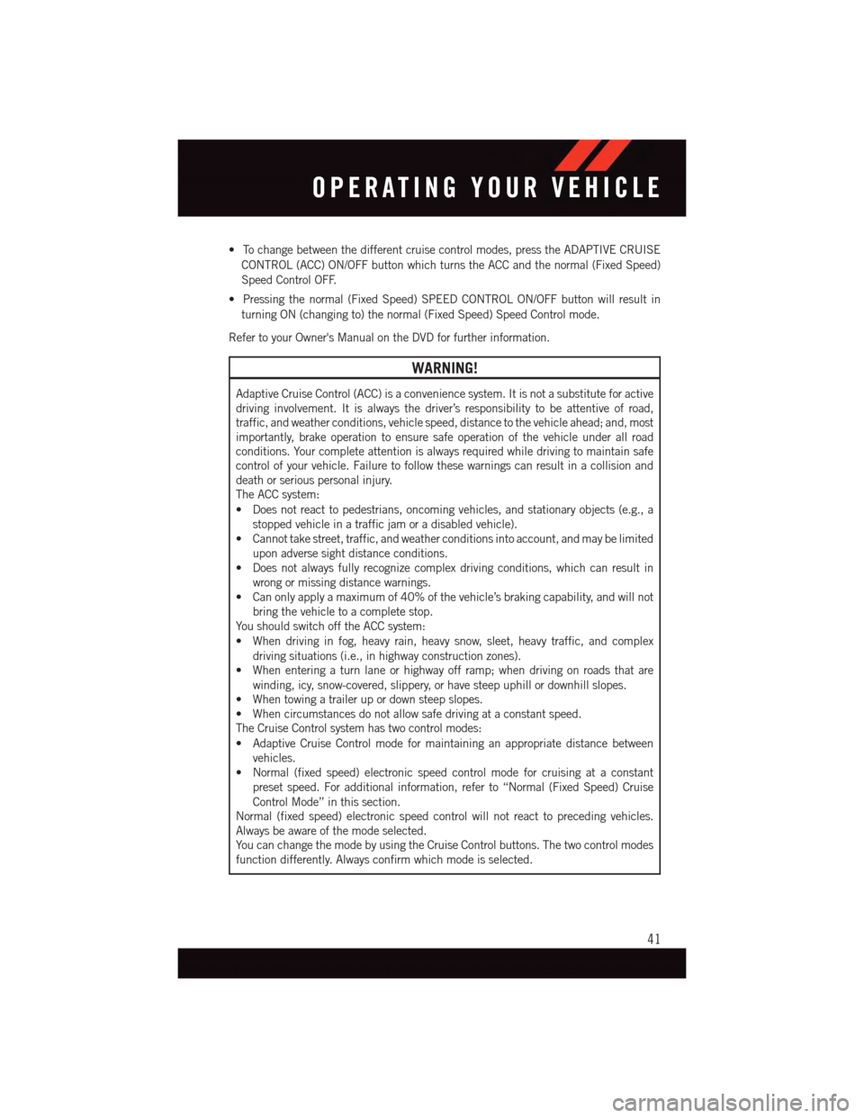
•Tochangebetweenthedifferentcruisecontrolmodes,presstheADAPTIVECRUISE
CONTROL (ACC) ON/OFF button which turns the ACC and the normal (Fixed Speed)
Speed Control OFF.
•Pressingthenormal(FixedSpeed)SPEEDCONTROLON/OFFbuttonwillresultin
turning ON (changing to) the normal (Fixed Speed) Speed Control mode.
Refer to your Owner's Manual on the DVD for further information.
WARNING!
Adaptive Cruise Control (ACC) is a convenience system. It is not a substitute for active
driving involvement. It is always the driver’s responsibility to be attentive of road,
traffic, and weather conditions, vehicle speed, distance to the vehicle ahead; and, most
importantly, brake operation to ensure safe operation of the vehicle under all road
conditions. Your complete attention is always required while driving to maintain safe
control of your vehicle. Failure to follow these warnings can result in a collision and
death or serious personal injury.
The ACC system:
•Doesnotreacttopedestrians,oncomingvehicles,andstationaryobjects(e.g.,a
stopped vehicle in a traffic jam or a disabled vehicle).
•Cannottakestreet,traffic,andweatherconditionsintoaccount,andmaybelimited
upon adverse sight distance conditions.
•Doesnotalwaysfullyrecognizecomplexdrivingconditions,whichcanresultin
wrong or missing distance warnings.
•Canonlyapplyamaximumof40%ofthevehicle’sbrakingcapability,andwillnot
bring the vehicle to a complete stop.
Yo u s h o u l d s w i t c h o f f t h e A C C s y s t e m :
•Whendrivinginfog,heavyrain,heavysnow,sleet,heavytraffic,andcomplex
driving situations (i.e., in highway construction zones).
•Whenenteringaturnlaneorhighwayofframp;whendrivingonroadsthatare
winding, icy, snow-covered, slippery, or have steep uphill or downhill slopes.
•Whentowingatrailerupordownsteepslopes.
•Whencircumstancesdonotallowsafedrivingataconstantspeed.
The Cruise Control system has two control modes:
•AdaptiveCruiseControlmodeformaintaininganappropriatedistancebetween
vehicles.
•Normal(fixedspeed)electronicspeedcontrolmodeforcruisingataconstant
preset speed. For additional information, refer to “Normal (Fixed Speed) Cruise
Control Mode” in this section.
Normal (fixed speed) electronic speed control will not react to preceding vehicles.
Always be aware of the mode selected.
Yo u c a n c h a n g e t h e m o d e b y u s i n g t h e C r u i s e C o n t r o l b u t t o n s . T h e t w o c o n t r o l m o d e s
function differently. Always confirm which mode is selected.
OPERATING YOUR VEHICLE
41
Page 45 of 220
This setting provides less reaction time than the “Far” setting, which allows for a more
dynamic driving experience.
More dynamic or aggressive drivers that want to avoid frequent warnings may prefer this
setting.
Refer to the Owner's Manual on the DVD for further details.
WARNING!
Forward Collision Warning (FCW) is not intended to avoid a collision on its own, nor can
FCW detect every type of potential collision. The driver has the responsibility to avoid
acollisionbycontrollingthevehicleviabrakingandsteering.Failuretofollowthis
warning could lead to serious injury or death.
PARKSENSE® REAR PARK ASSIST
The four ParkSense®sensors, located in the rear fascia/bumper, monitor the area behind
the vehicle that is within the sensors’ field of view.
The sensors can detect obstacles from approximately 12 in (30 cm) up to 79 in (200 cm)
from the rear bumper while the vehicle is in REVERSE, a warning will display in the Driver
Information Display (DID) only when (Sound and Display is selected from the Uconnect®
System). As the vehicle moves closer to the obstacle, the (DID) will show fewer arcs and
the sound tone will change from slow, to fast, to continuous.
Refer to your Owner's Manual on the DVD for further details.
AUTOSTICK
AutoStick is a driver-interactive transmission feature providing manual shift control,
giving you more control of the vehicle. AutoStick allows you to maximize engine braking,
eliminate undesirable upshifts and downshifts, and improve overall vehicle performance.
This system can also provide you with more control during passing, city driving, cold
slippery conditions, mountain driving, trailer towing, and many other situations.
Operation
When the shift lever is in the DRIVE (D) position, the transmission will operate automatically,
shifting between the eight available gears. To activate AutoStick, move the shift lever into the
MANUAL (M) position (beside the DRIVE position). The current transmission gear will be
displayed in the instrument cluster, along with a highlighted "M" (Manual) indication. When
the shift lever is in the MANUAL (M) position, tap the shift lever forward (-) (or tap the (-) shift
paddle on the steering wheel, if equipped) to downshift the transmission to the next lower
gear, or tap the lever rearward (+) (or tap the (+) shift paddle, if equipped) to command an
upshift.
OPERATING YOUR VEHICLE
43