ECO mode DODGE CHALLENGER 2015 3.G User Guide
[x] Cancel search | Manufacturer: DODGE, Model Year: 2015, Model line: CHALLENGER, Model: DODGE CHALLENGER 2015 3.GPages: 220, PDF Size: 30.96 MB
Page 3 of 220
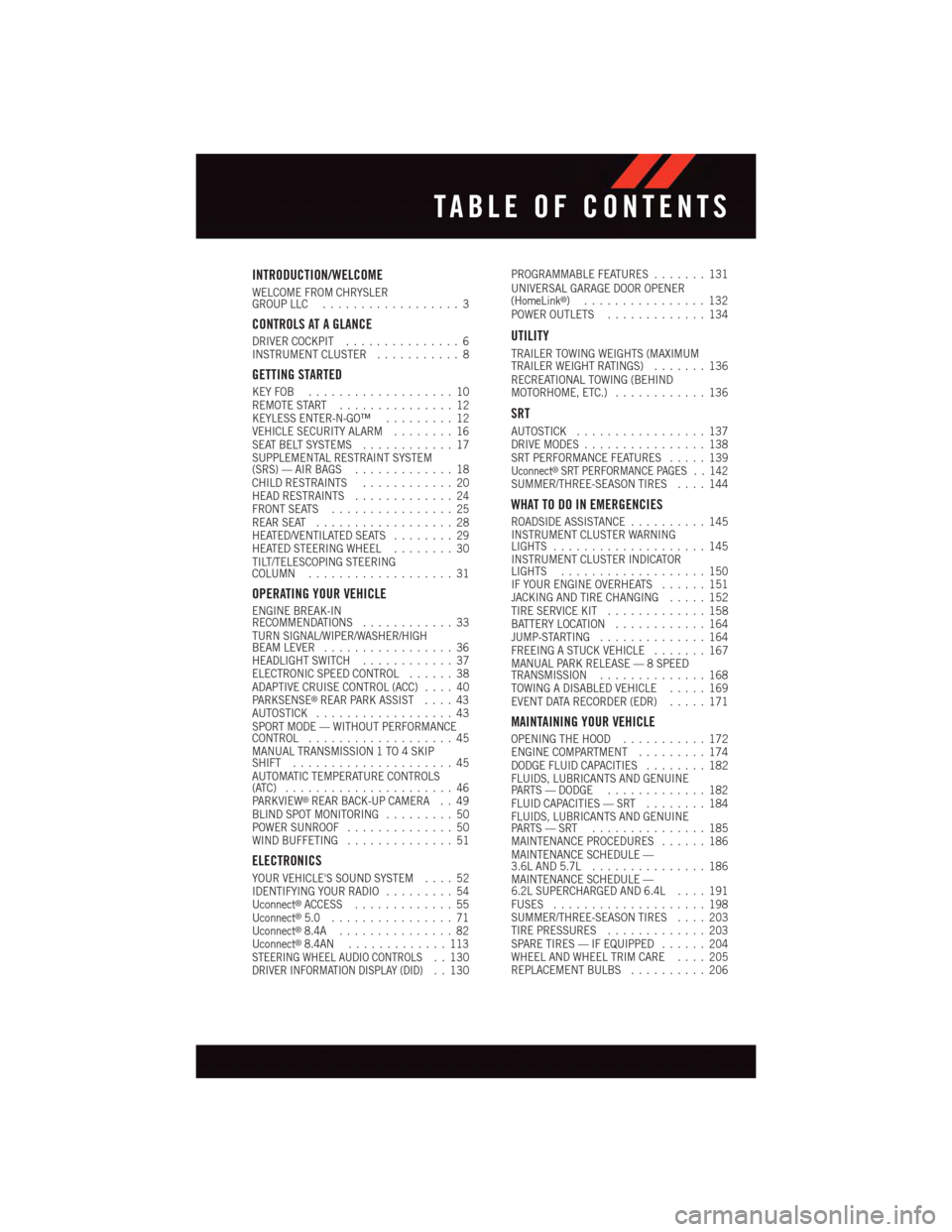
INTRODUCTION/WELCOME
WELCOME FROM CHRYSLERGROUP LLC..................3
CONTROLS AT A GLANCE
DRIVER COCKPIT...............6INSTRUMENT CLUSTER...........8
GETTING STARTED
KEY FOB . . . . . . . . . . . . . . . . . . . 10REMOTE START . . . . . . . . . . . . . . . 12KEYLESS ENTER-N-GO™.........12VEHICLE SECURITY ALARM........16SEAT BELT SYSTEMS............17SUPPLEMENTAL RESTRAINT SYSTEM(SRS) — AIR BAGS.............18CHILD RESTRAINTS............20HEAD RESTRAINTS.............24FRONT SEATS................25REAR SEAT..................28HEATED/VENTILATED SEATS........29HEATED STEERING WHEEL........30TILT/TELESCOPING STEERINGCOLUMN...................31
OPERATING YOUR VEHICLE
ENGINE BREAK-INRECOMMENDATIONS............33TURN SIGNAL/WIPER/WASHER/HIGHBEAM LEVER.................36HEADLIGHT SWITCH............37ELECTRONIC SPEED CONTROL......38ADAPTIVE CRUISE CONTROL (ACC)....40PA R K S E N S E®REAR PARK ASSIST....43AUTOSTICK..................43SPORT MODE — WITHOUT PERFORMANCECONTROL...................45MANUAL TRANSMISSION 1 TO 4 SKIPSHIFT.....................45AUTOMATIC TEMPERATURE CONTROLS(ATC) . . . . . . . . . . . . . . . . . . . . . . 46PA R K V I E W®REAR BACK-UP CAMERA . . 49BLIND SPOT MONITORING.........50POWER SUNROOF..............50WIND BUFFETING..............51
ELECTRONICS
YOUR VEHICLE'S SOUND SYSTEM....52IDENTIFYING YOUR RADIO.........54Uconnect®ACCESS.............55Uconnect®5.0 . . . . . . . . . . . . . . . . 71Uconnect®8.4A...............82Uconnect®8.4AN.............113STEERING WHEEL AUDIO CONTROLS..130DRIVER INFORMATION DISPLAY (DID)..130
PROGRAMMABLE FEATURES.......131UNIVERSAL GARAGE DOOR OPENER(HomeLink®)................132POWER OUTLETS.............134
UTILITY
TRAILER TOWING WEIGHTS (MAXIMUMTRAILER WEIGHT RATINGS).......136RECREATIONAL TOWING (BEHINDMOTORHOME, ETC.)............136
SRT
AUTOSTICK.................137DRIVE MODES................138SRT PERFORMANCE FEATURES.....139Uconnect®SRT PERFORMANCE PAGES . . 142SUMMER/THREE-SEASON TIRES....144
WHAT TO DO IN EMERGENCIES
ROADSIDE ASSISTANCE..........145INSTRUMENT CLUSTER WARNINGLIGHTS....................145INSTRUMENT CLUSTER INDICATORLIGHTS...................150IF YOUR ENGINE OVERHEATS......151JACKING AND TIRE CHANGING.....152TIRE SERVICE KIT.............158BATTERY LOCATION............164JUMP-STARTING..............164FREEING A STUCK VEHICLE.......167MANUAL PARK RELEASE — 8 SPEEDTRANSMISSION..............168TOWING A DISABLED VEHICLE.....169EVENT DATA RECORDER (EDR).....171
MAINTAINING YOUR VEHICLE
OPENING THE HOOD...........172ENGINE COMPARTMENT.........174DODGE FLUID CAPACITIES........182FLUIDS, LUBRICANTS AND GENUINEPA RT S — D O D G E.............182FLUID CAPACITIES — SRT........184FLUIDS, LUBRICANTS AND GENUINEPA RT S — S RT . . . . . . . . . . . . . . . 1 8 5MAINTENANCE PROCEDURES......186MAINTENANCE SCHEDULE —3.6L AND 5.7L...............186MAINTENANCE SCHEDULE —6.2L SUPERCHARGED AND 6.4L....191FUSES....................198SUMMER/THREE-SEASON TIRES....203TIRE PRESSURES.............203SPARE TIRES — IF EQUIPPED......204WHEEL AND WHEEL TRIM CARE....205REPLACEMENT BULBS..........206
TABLE OF CONTENTS
Page 6 of 220
VEHICLES SOLD IN CANADA
With respect to any vehicles sold in Canada, the name Chrysler Group LLC shall be
deemed to be deleted and the name Chrysler Canada Inc. used in substitution (excluding
legal lines).
WARNING!
•Pedalsthatcannotmovefreelycancauselossofvehiclecontrolandincreasethe
risk of serious personal injury.
•Alwaysmakesurethatobjectscannotfallintothedriverfootwellwhilethevehicle
is moving. Objects can become trapped under the brake pedal and accelerator
pedal causing a loss of vehicle control.
•Failuretoproperlyfollowfloormatinstallationormountingcancauseinterference
with the brake pedal and accelerator pedal operation causing loss of control of the
vehicle.
•Neverleavechildrenaloneinavehicle,orwithaccesstoanunlockedvehicle.
Allowing children to be in a vehicle unattended is dangerous for a number of
reasons. A child or others could be seriously or fatally injured. Children should be
warned not to touch the parking brake, brake pedal or the shift lever/transmission
gear selector.
•Donotleavethekeyfobinornearthevehicle,orinalocationaccessibletochildren,
and do not leave the ignition of a vehicle equipped with Keyless Enter-N-Go in the
ACC or ON/RUN mode. A child could operate power windows, other controls, or
move the vehicle.
•Neverusethe“PARK”positionasasubstitutefortheparkingbrake.Alwaysapply
the parking brake fully when parked to guard against vehicle movement and
possible injury or damage.
•RefertoyourOwner'sManualontheDVDforfurtherdetails.
INTRODUCTION/WELCOME
4
Page 12 of 220
KEY FOB
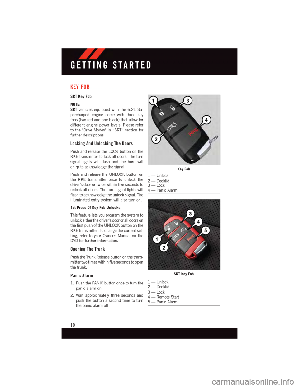
SRT Key Fob
NOTE:
SRTvehicles equipped with the 6.2L Su-
percharged engine come with three key
fobs (two red and one black) that allow for
different engine power levels. Please refer
to the "Drive Modes" in “SRT” section for
further descriptions
Locking And Unlocking The Doors
Push and release the LOCK button on the
RKE transmitter to lock all doors. The turn
signal lights will flash and the horn will
chirp to acknowledge the signal.
Push and release the UNLOCK button on
the RKE transmitter once to unlock the
driver's door or twice within five seconds to
unlock all doors. The turn signal lights will
flash to acknowledge the unlock signal. The
illuminated entry system will also turn on.
1st Press Of Key Fob Unlocks
This feature lets you program the system to
unlock either the driver's door or all doors on
the first push of the UNLOCK button on the
RKE transmitter. To change the current set-
ting, refer to your Owner's Manual on the
DVD for further information.
Opening The Trunk
Push the Trunk Release button on the trans-
mitter two times within five seconds to open
the trunk.
Panic Alarm
1. Push the PANIC button once to turn the
panic alarm on.
2. Wait approximately three seconds and
push the button a second time to turn
the panic alarm off.
Key Fob
1—Unlock
2—Decklid3—Lock4—PanicAlarm
SRT Key Fob
1—Unlock2—Decklid
3—Lock4—RemoteStart5—PanicAlarm
GETTING STARTED
10
Page 13 of 220
Emergency Key
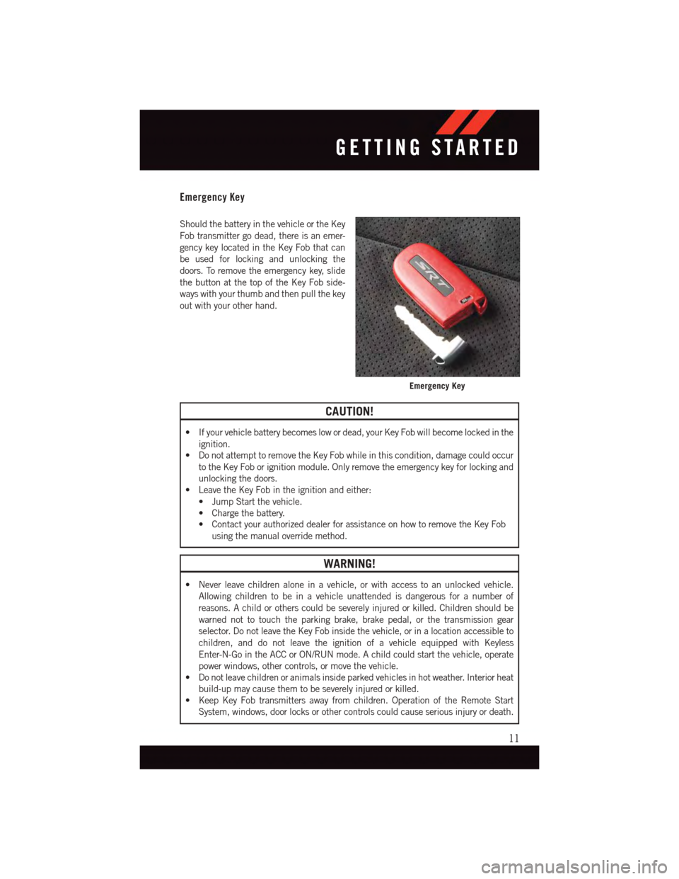
Should the battery in the vehicle or the Key
Fob transmitter go dead, there is an emer-
gency key located in the Key Fob that can
be used for locking and unlocking the
doors. To remove the emergency key, slide
the button at the top of the Key Fob side-
ways with your thumb and then pull the key
out with your other hand.
CAUTION!
•Ifyourvehiclebatterybecomeslowordead,yourKeyFobwillbecomelockedinthe
ignition.
•DonotattempttoremovetheKeyFobwhileinthiscondition,damagecouldoccur
to the Key Fob or ignition module. Only remove the emergency key for locking and
unlocking the doors.
•LeavetheKeyFobintheignitionandeither:
•JumpStartthevehicle.
•Chargethebattery.
•ContactyourauthorizeddealerforassistanceonhowtoremovetheKeyFob
using the manual override method.
WARNING!
•Neverleavechildrenaloneinavehicle,orwithaccesstoanunlockedvehicle.
Allowing children to be in a vehicle unattended is dangerous for a number of
reasons. A child or others could be severely injured or killed. Children should be
warned not to touch the parking brake, brake pedal, or the transmission gear
selector. Do not leave the Key Fob inside the vehicle, or in a location accessible to
children, and do not leave the ignition of a vehicle equipped with Keyless
Enter-N-Go in the ACC or ON/RUN mode. A child could start the vehicle, operate
power windows, other controls, or move the vehicle.
•Donotleavechildrenoranimalsinsideparkedvehiclesinhotweather.Interiorheat
build-up may cause them to be severely injured or killed.
•KeepKeyFobtransmittersawayfromchildren.OperationoftheRemoteStart
System, windows, door locks or other controls could cause serious injury or death.
Emergency Key
GETTING STARTED
11
Page 24 of 220
Installing The Child Restraint Using The LATCH Lower Anchors
NOTE:
Never“share” a LATCH anchorage with two or more child restraints.
1. Loosen the adjusters on the lower straps and on the tether strap of the child seat so that
you can more easily attach the hooks or connectors to the vehicle anchorages.
2. Attach the lower hooks or connectors of the child restraint to the lower anchorages in
the selected seating position.
3. If the child restraint has a tether strap, connect it to the top tether anchorage. See
below for directions to attach a tether anchor.
4. Tighten all of the straps as you push the child restraint rearward and downward into the
seat. Remove slack in the straps according to the child restraint manufacturer’s
instructions.
5. Test that the child restraint is installed tightly by pulling back and forth on the child
seat at the belt path. It should not move more than 1 inch (25.4 mm) in any direction.
Installing The Child Restraint Using The Vehicle Seat Belts
The seat belts in the passenger seating positions are equipped with a Switchable
Automatic Locking Retractor (ALR) that is designed to keep the lap portion of the seat belt
tight around the child restraint. Any seat belt system will loosen with time, so check the
belt occasionally, and pull it tight if necessary.
Tether Weight Limit
Always use the tether anchor when using the seat belt to install a forward facing child
restraint, up to the recommended weight limit of the child restraint.
To Install A Child Seat Using An ALR:
1. Pull enough of the seat belt webbing from the retractor to pass it through the belt path
of the child restraint. Do not twist the belt webbing in the belt path.
2. Slide the latch plate into the buckle until you hear a “click.”
3. Pull on the webbing to make the lap portion tight against the child seat.
4. To lock the seat belt, pull down on the shoulder part of the belt until you have pulled
all the seat belt webbing out of the retractor. Then, allow the webbing to retract back
into the retractor. As the webbing retracts, you will hear a clicking sound. This means
the seat belt is now in the Automatic Locking mode.
5. Try to pull the webbing out of the retractor. If it is locked, you should not be able to pull
out any webbing. If the retractor is not locked, repeat the last step.
6. Finally, pull up on any extra webbing to tighten the lap portion around the child
restraint while you push the child restraint rearward and downward into the vehicle
seat.
GETTING STARTED
22
Page 31 of 220
HEATED/VENTILATED SEATS
Front Heated Seats
The front heated seats control buttons are located within the climate or controls screen of
the touchscreen.
•Presstheheatedseatbuttononce to turn the High setting On.
•PresstheheatedseatbuttonasecondtimetoturntheLowsettingOn.
•PresstheheatedseatbuttonathirdtimetoturntheheatingelementsOff.
If the High-level setting is selected, the system will automatically switch to Low-level after
approximately 60 minutes. The Low-level setting will turn Off automatically after approxi-
mately 45 minutes.
NOTE:
Vehicle Equipped With Remote Start
On models that are equipped with remote start, this feature can be programmed to come
on during a remote start through the Uconnect®system. Refer to “Uconnect®Settings”
in “Understanding Your Instrument Panel” in the Owner's Manual on the DVD.
WARNING!
•Personswhoareunabletofeelpaintotheskinbecauseofadvancedage,chronic
illness, diabetes, spinal cord injury, medication, alcohol use, exhaustion or other
physical conditions must exercise care when using the seat heater. It may cause
burns even at low temperatures, especially if used for long periods of time.
•Donotplaceanythingontheseatthatinsulatesagainstheat,suchasablanketor
cushion. This may cause the seat heater to overheat. Sitting in a seat that has been
overheated could cause serious burns due to the increased surface temperature of
the seat.
Front Ventilated Seats
Located in the seat cushion and seatback are small fans that draw the air from the
passenger compartment and pull air through fine perforations in the seat cover to help
keep the driver and front passenger cooler in higher ambient temperatures.
There are two ventilated seat control buttons located in the touchscreen that allow the
driver and passenger to operate the seats independently.
The ventilated seat buttons are used to control the speed of the fans located in the seat.
GETTING STARTED
29
Page 32 of 220
To o p e r a t e t h e s y s t e m , p r e s s t h e “ C o n t r o l s ” b u t t o n o n t o u c h s c r e e n l o c a t e d o n t h e b o t t o m
of the Uconnect®display.
•Presstheventilatedseatbuttononce to choose HIGH.
•PresstheventilatedseatbuttonasecondtimetochooseLOW.
•PresstheventilatedseatbuttonathirdtimetoturntheventilatedseatOFF.
NOTE:
Vehicle Equipped With Remote Start
On models that are equipped with remote start, this feature can be programmed to come
on during a remote start through the Uconnect®system. Refer to “Uconnect®Settings”
in “Understanding Your Instrument Panel” in the Owner's Manual on the DVD.
HEATED STEERING WHEEL
The steering wheel contains a heating element that heats the steering wheel to one
temperature setting.
The heated steering wheel control button is located within the Uconnect®system. You can
gain access to the control buttons through the climate screen or the controls screen.
•Presstheheatedsteeringwheelbuttononce to turn the heating element ON.
•Presstheheatedsteeringwheelbuttonasecondtimetoturntheheatingelement
OFF.
Once the heated steering wheel has been turned on, it will operate for up to 80 minutes
before automatically shutting off. The heated steering wheel can shut off early or may not
turn on when the steering wheel is already warm.
NOTE:
Vehicle Equipped With Remote Start
On models that are equipped with remote start, this feature can be programmed to come
on during a remote start through the Uconnect®system. Refer to “Uconnect®Settings”
in “Understanding Your Instrument Panel” in the Owner's Manual on the DVD.
WARNING!
•Personswhoareunabletofeelpaintotheskinbecauseofadvancedage,chronic
illness, diabetes, spinal cord injury, medication, alcohol use, exhaustion, or other
physical conditions must exercise care when using the steering wheel heater. It may
cause burns even at low temperatures, especially if used for long periods.
•Donotplaceanythingonthesteeringwheelthatinsulatesagainstheat,suchasa
blanket or steering wheel covers of any type and material. This may cause the
steering wheel heater to overheat.
GETTING STARTED
30
Page 35 of 220
ENGINE BREAK-IN RECOMMENDATIONS
For vehicles equipped with the 3.6L or 5.7L use the following engine break-in recom-
mendations:
Alongbreak-inperiodisnotrequiredforthedrivetrain(engine,transmission,clutch,and
rear axle) in your new vehicle.
Drive moderately during the first 300 mi (500 km). After the initial 60 mi (100 km),
speeds up to 50 or 55 mph (80 or 90 km/h) are desirable.
While cruising, brief full-throttle acceleration within the limits of local traffic laws
contributes to a good break-in. However, wide-open throttle acceleration in low gear can
be detrimental and should be avoided.
The engine oil, transmission fluid, and axle lubricant installed at the factory is high-quality
and energy-conserving. Oil, fluid, and lubricant changes should be consistent with
anticipated climate and conditions under which vehicle operations will occur. For the
recommended viscosity and quality grades, refer to “Maintenance Procedures” in “Main-
taining Your Vehicle”.
CAUTION!
Never use Non-Detergent Oil or Straight Mineral Oil in the engine or damage may
result.
NOTE:
Anewenginemayconsumesomeoilduringitsfirstfewthousandmiles(kilometers)of
operation. This should be considered a normal part of the break-in and not interpreted as
an indication of difficulty. Please check your oil level with the engine oil indicator often
during the break in period. Add oil as required.
For vehicles equipped with the 6.4L use the following engine break-in recommendations:
Despite modern technology and World Class manufacturing methods, the moving parts of
the vehicle must still wear in with each other. This wearing in occurs mainly during the first
500 miles (805 km) and continues through the first oil change interval.
It is recommended for the operator to observe the following driving behaviors during the
new vehicle break-in period:
0to100miles(0to161km):
•Donotallowtheenginetooperateatidleforanextendedperiodoftime.
•Depresstheacceleratorpedalslowlyandnotmorethanhalfwaytoavoidrapid
acceleration.
•Avoidaggressivebraking.
OPERATING YOUR VEHICLE
33
Page 36 of 220
•Drivewiththeenginespeedlessthan3,500RPM.
•Maintainvehiclespeedbelow55mph(88km/h)andobservelocalspeedlimits.
100 to 300 miles (161 to 483 km):
•Depresstheacceleratorpedalslowlyandnotmorethanhalfwaytoavoidrapid
acceleration in lower gears (1st to 3rd gears).
•Avoidaggressivebraking.
•Drivewiththeenginespeedlessthan5,000RPM.
•Maintainvehiclespeedbelow70mph(112km/h)andobservelocalspeedlimits.
300 to 500 miles (483 to 805 km):
•Exercisethefullenginerpmrange,shiftingmanually(paddlesorgearshift)athigher
rpms when possible.
•Donotperformsustainedoperationwiththeacceleratorpedalatwideopenthrottle.
•Maintainvehiclespeedbelow85mph(136km/h)andobservelocalspeedlimits.
For the first 1500 mi (2414 km):
•Donotparticipateintrackevents,sportdrivingschools,orsimilaractivitiesduringthe
first 1500 mi (2414 km).
NOTE:
Check engine oil with every refueling and add if necessary. Oil and fuel consumption may
be higher through the first oil change interval.
SRT Engine Break-In Recommendations
SRT Engine Break-In Recommendations: The following tips will be helpful in obtaining
optimum performance and maximum durability for your new SRT Vehicle.
Despite modern technology and World Class manufacturing methods, the moving parts of
the vehicle must still wear in with each other. This wearing in occurs mainly during the first
500 miles (805 km) and continues through the first oil change interval.
It is recommended for the operator to observe the following driving behaviors during the
new vehicle break-in period:
0to100miles(0to161km):
•Donotallowtheenginetooperateatidleforanextendedperiodoftime.
•Depresstheacceleratorpedalslowlyandnotmorethanhalfwaytoavoidrapid
acceleration.
•Avoidaggressivebraking.
OPERATING YOUR VEHICLE
34
Page 42 of 220
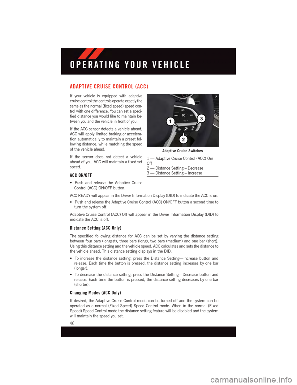
ADAPTIVE CRUISE CONTROL (ACC)
If your vehicle is equipped with adaptive
cruise control the controls operate exactly the
same as the normal (fixed speed) speed con-
trol with one difference. You can set a speci-
fied distance you would like to maintain be-
tween you and the vehicle in front of you.
If the ACC sensor detects a vehicle ahead,
ACC will apply limited braking or accelera-
tion automatically to maintain a preset fol-
lowing distance, while matching the speed
of the vehicle ahead.
If the sensor does not detect a vehicle
ahead of you, ACC will maintain a fixed set
speed.
ACC ON/OFF
•PushandreleasetheAdaptiveCruise
Control (ACC) ON/OFF button.
ACC READY will appear in the Driver Information Display (DID) to indicate the ACC is on.
•PushandreleasetheAdaptiveCruiseControl(ACC)ON/OFFbuttonasecondtimeto
turn the system off.
Adaptive Cruise Control (ACC) Off will appear in the Driver Information Display (DID) to
indicate the ACC is off.
Distance Setting (ACC Only)
The specified following distance for ACC can be set by varying the distance setting
between four bars (longest), three bars (long), two bars (medium) and one bar (short).
Using this distance setting and the vehicle speed, ACC calculates and sets the distance to
the vehicle ahead. This distance setting displays in the DID.
•Toincreasethedistancesetting,presstheDistanceSetting—Increasebuttonand
release. Each time the button is pressed, the distance setting increases by one bar
(longer).
•Todecreasethedistancesetting,presstheDistanceSetting—Decreasebuttonand
release. Each time the button is pressed, the distance setting decreases by one bar
(shorter).
Changing Modes (ACC Only)
If desired, the Adaptive Cruise Control mode can be turned off and the system can be
operated as a normal (Fixed Speed) Speed Control mode. When in the normal (Fixed
Speed) Speed Control mode the distance setting feature will be disabled and the system
will maintain the speed you set.
Adaptive Cruise Switches
1—AdaptiveCruiseControl(ACC)On/Off2—DistanceSetting–Decrease3—DistanceSetting–Increase
OPERATING YOUR VEHICLE
40