instrument panel DODGE CHALLENGER 2015 3.G User Guide
[x] Cancel search | Manufacturer: DODGE, Model Year: 2015, Model line: CHALLENGER, Model: DODGE CHALLENGER 2015 3.GPages: 220, PDF Size: 30.96 MB
Page 20 of 220
SUPPLEMENTAL RESTRAINT SYSTEM (SRS) — AIR BAGS
Air Bag System Components
Yo u r v e h i c l e m a y b e e q u i p p e d w i t h t h e f o l l o w i n g a i r b a g s y s t e m c o m p o n e n t s :
•OccupantRestraintController(ORC)
•AirBagWarningLight
•SteeringWheelandColumn
•InstrumentPanel
•KneeImpactBolsters
•AdvancedFrontAirBags
•SupplementalSideAirBags
•FrontandSideImpactSensors
•SeatBeltPretenioners
•SeatBeltBuckleSwitch
•SeatTrackPositionSensors
Advanced Front Air Bags
•ThisvehiclehasAdvancedFrontAirBagsforboththedriverandfrontpassengerasa
supplement to the seat belt restraint systems. The Advanced Front Air Bags will not
deploy in every type of collision.
•AdvancedFrontAirBagsaredesignedtoprovideadditionalprotectionbysupplement-
ing the seat belts. Advanced Front Air Bags are not expected to reduce the risk of injury
in rear, side, or rollover collisions.
•TheAdvancedFrontAirBagswillnotdeployinallfrontalcollisions,includingsome
that may produce substantial vehicle damage — for example, some pole collisions,
truck underrides, and angle offset collisions.
•Ontheotherhand,dependingonthetypeandlocationofimpact,AdvancedFrontAir
Bags may deploy in crashes with little vehicle front-end damage but that produce a
severe initial deceleration.
•Becauseairbagsensorsmeasurevehicledecelerationovertime,vehiclespeedand
damage by themselves are not good indicators of whether or not an air bag should have
deployed.
•Seatbeltsarenecessaryforyourprotectioninallcollisions,andalsoareneededtohelp
keep you in position, away from an inflating air bag.
•Theairbagsmustbereadytoinflateforyourprotectioninacollision.TheOccupant
Restraint Controller (ORC) monitors the internal circuits and interconnecting wiring
associated with air bag system electrical components.
GETTING STARTED
18
Page 21 of 220
•TheORCturnsontheAirBagWarningLightintheinstrumentpanelforapproximately
four to eight seconds for a self-check when the ignition switch is first turned to the
ON/RUN position. After the self-check, the Air Bag Warning Light will turn off. If the
ORC detects a malfunction in any part of the system, it turns on the Air Bag Warning
Light, either momentarily or continuously. A single chime will sound to alert you if the
light comes on again after initial startup.
•TheORCmonitorsthereadinessoftheelectronicpartsoftheairbagsystemwhenever
the ignition switch is in the START or ON/RUN position. If the ignition switch is in the
OFF position or in the ACC position, the air bag system is not on and the air bags will
not inflate.
•IftheAirBagWarningLightintheinstrumentpanelisnotonduringthefourtoeight
seconds when the ignition switch is first turned to the ON/RUN position, stays on, or
turns on while driving, have the vehicle serviced by an authorized service center
immediately.
NOTE:
If the speedometer, tachometer, or any engine related gauges are not working, the
Occupant Restraint Controller (ORC) may also be disabled. In this condition the air bags
may not be ready to inflate for your protection. Have an authorized dealer service the air
bag system immediately.
•Afteranycollision,thevehicleshouldbetakentoanauthorizeddealerimmediately.
•Donotdriveyourvehicleaftertheairbagshavedeployed.Ifyouareinvolvedinanother
collision, the air bags will not be in place to protect you.
•Ifitisnecessarytomodifytheairbagsystemforpersonswithdisabilities,contactyour
authorized dealer.
•RefertotheOwner'sManualontheDVDforfurtherdetailsregardingtheSupplemental
Restraint System (SRS).
Supplemental Side Air Bags
•ThisvehicleisequippedwithSupplementalSeat-MountedSideAirBags(SABs)
located in the outboard side of the front seats. The SABs are marked with a SRS
AIRBAG or AIRBAG label sewn into the outboard side of the seats.
•ThisvehicleisequippedwithSupplementalSideAirBagInflatableCurtains(SABICs)
located above the side windows. The trim covering the SABICs is labeled SRS AIRBAG
or AIRBAG. The SABICs may help reduce the risk of partial or complete ejection of
vehicle occupants through side windows in certain side impact events.
•TheSABICsandSABs(“SideAirBags”)aredesignedtoactivateincertainside
impacts and certain rollover events. The Occupant Restraint Controller (“ORC”)
determines whether the deployment of the Side Air Bags in a particular side impact or
rollover event is appropriate, based on the severity and type of collision. Vehicle damage
by itself is not a good indicator of whether or not Side Air Bags should have deployed.
GETTING STARTED
19
Page 31 of 220
HEATED/VENTILATED SEATS
Front Heated Seats
The front heated seats control buttons are located within the climate or controls screen of
the touchscreen.
•Presstheheatedseatbuttononce to turn the High setting On.
•PresstheheatedseatbuttonasecondtimetoturntheLowsettingOn.
•PresstheheatedseatbuttonathirdtimetoturntheheatingelementsOff.
If the High-level setting is selected, the system will automatically switch to Low-level after
approximately 60 minutes. The Low-level setting will turn Off automatically after approxi-
mately 45 minutes.
NOTE:
Vehicle Equipped With Remote Start
On models that are equipped with remote start, this feature can be programmed to come
on during a remote start through the Uconnect®system. Refer to “Uconnect®Settings”
in “Understanding Your Instrument Panel” in the Owner's Manual on the DVD.
WARNING!
•Personswhoareunabletofeelpaintotheskinbecauseofadvancedage,chronic
illness, diabetes, spinal cord injury, medication, alcohol use, exhaustion or other
physical conditions must exercise care when using the seat heater. It may cause
burns even at low temperatures, especially if used for long periods of time.
•Donotplaceanythingontheseatthatinsulatesagainstheat,suchasablanketor
cushion. This may cause the seat heater to overheat. Sitting in a seat that has been
overheated could cause serious burns due to the increased surface temperature of
the seat.
Front Ventilated Seats
Located in the seat cushion and seatback are small fans that draw the air from the
passenger compartment and pull air through fine perforations in the seat cover to help
keep the driver and front passenger cooler in higher ambient temperatures.
There are two ventilated seat control buttons located in the touchscreen that allow the
driver and passenger to operate the seats independently.
The ventilated seat buttons are used to control the speed of the fans located in the seat.
GETTING STARTED
29
Page 32 of 220
To o p e r a t e t h e s y s t e m , p r e s s t h e “ C o n t r o l s ” b u t t o n o n t o u c h s c r e e n l o c a t e d o n t h e b o t t o m
of the Uconnect®display.
•Presstheventilatedseatbuttononce to choose HIGH.
•PresstheventilatedseatbuttonasecondtimetochooseLOW.
•PresstheventilatedseatbuttonathirdtimetoturntheventilatedseatOFF.
NOTE:
Vehicle Equipped With Remote Start
On models that are equipped with remote start, this feature can be programmed to come
on during a remote start through the Uconnect®system. Refer to “Uconnect®Settings”
in “Understanding Your Instrument Panel” in the Owner's Manual on the DVD.
HEATED STEERING WHEEL
The steering wheel contains a heating element that heats the steering wheel to one
temperature setting.
The heated steering wheel control button is located within the Uconnect®system. You can
gain access to the control buttons through the climate screen or the controls screen.
•Presstheheatedsteeringwheelbuttononce to turn the heating element ON.
•Presstheheatedsteeringwheelbuttonasecondtimetoturntheheatingelement
OFF.
Once the heated steering wheel has been turned on, it will operate for up to 80 minutes
before automatically shutting off. The heated steering wheel can shut off early or may not
turn on when the steering wheel is already warm.
NOTE:
Vehicle Equipped With Remote Start
On models that are equipped with remote start, this feature can be programmed to come
on during a remote start through the Uconnect®system. Refer to “Uconnect®Settings”
in “Understanding Your Instrument Panel” in the Owner's Manual on the DVD.
WARNING!
•Personswhoareunabletofeelpaintotheskinbecauseofadvancedage,chronic
illness, diabetes, spinal cord injury, medication, alcohol use, exhaustion, or other
physical conditions must exercise care when using the steering wheel heater. It may
cause burns even at low temperatures, especially if used for long periods.
•Donotplaceanythingonthesteeringwheelthatinsulatesagainstheat,suchasa
blanket or steering wheel covers of any type and material. This may cause the
steering wheel heater to overheat.
GETTING STARTED
30
Page 39 of 220
High Beam Operation
Push the lever forward to activate the high beams. Pull the lever toward you for flash to
pass.
NOTE:
For safe driving, turn off the high beams when oncoming traffic is present to prevent
headlight glare and as a courtesy to other motorists.
HEADLIGHT SWITCH
Automatic Headlights/Parking Lights/Headlights
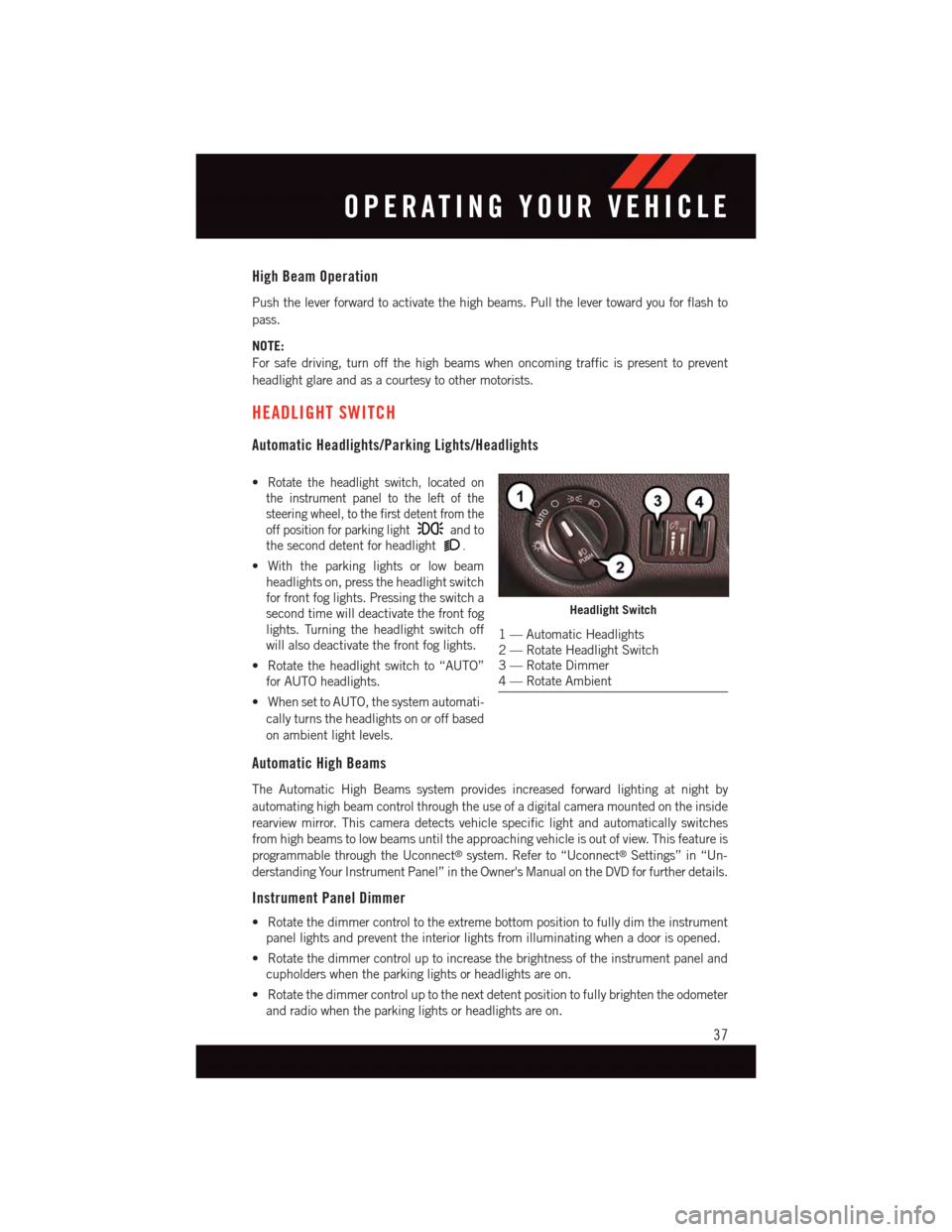
•Rotate the headlight switch, located on
the instrument panel to the left of the
steering wheel, to the first detent from the
off position for parking lightand to
the second detent for headlight.
•Withtheparkinglightsorlowbeam
headlights on, press the headlight switch
for front fog lights. Pressing the switch a
second time will deactivate the front fog
lights. Turning the headlight switch off
will also deactivate the front fog lights.
•Rotatetheheadlightswitchto“AUTO”
for AUTO headlights.
•WhensettoAUTO,thesystemautomati-
cally turns the headlights on or off based
on ambient light levels.
Automatic High Beams
The Automatic High Beams system provides increased forward lighting at night by
automating high beam control through the use of a digital camera mounted on the inside
rearview mirror. This camera detects vehicle specific light and automatically switches
from high beams to low beams until the approaching vehicle is out of view. This feature is
programmable through the Uconnect®system. Refer to “Uconnect®Settings” in “Un-
derstanding Your Instrument Panel” in the Owner's Manual on the DVD for further details.
Instrument Panel Dimmer
•Rotatethedimmercontroltotheextremebottompositiontofullydimtheinstrument
panel lights and prevent the interior lights from illuminating when a door is opened.
•Rotatethedimmercontroluptoincreasethebrightnessoftheinstrumentpaneland
cupholders when the parking lights or headlights are on.
•Rotatethedimmercontroluptothenextdetentpositiontofullybrightentheodometer
and radio when the parking lights or headlights are on.
Headlight Switch
1—AutomaticHeadlights2—RotateHeadlightSwitch3—RotateDimmer4—RotateAmbient
OPERATING YOUR VEHICLE
37
Page 47 of 220
To d i s e n g a g e A u t o S t i c k m o d e , r e t u r n t h e s h i f t l e v e r t o t h e D R I V E p o s i t i o n , o r p r e s s a n d
hold the (+) shift paddle (if equipped, and the shift lever is already in DRIVE) until “D” is
once again indicated in the instrument cluster. You can shift in or out of the AutoStick
mode at any time without taking your foot off the accelerator pedal.
WARNING!
Do not downshift for additional engine braking on a slippery surface. The drive wheels
could lose their grip and the vehicle could skid, causing a collision or personal injury.
SPORT MODE — WITHOUT PERFORMANCE CONTROL
Yo u r v e h i c l e i s e q u i p p e d w i t h a S p o r t M o d e f e a t u r e . T h i s m o d e i s a c o n f i g u r a t i o n s e t u p
for typical enthusiast driving. The engine, transmission (when equipped with automatic
transmission), and steering systems are all set to their SPORT settings. Sport Mode will
provide improved throttle response and modified shifting for an enhanced driving
experience, as well the greatest amount of steering feel. This mode may be activated and
deactivated by pressing the Sport button on the instrument panel switch bank.
For vehicles equipped with Drive Modes, Refer to “Performance Control — If Equipped”
within “Uconnect Settings” in “Understanding Your Instrument Panel” chapter on your
DVD or in the “Drive Mode Supplement” within your Owners information kit for further
information.
MANUAL TRANSMISSION 1 TO 4 SKIP SHIFT
There are times when you must shift the transmission directly from first gear to fourth gear
instead of from first gear to second gear. This is to help you get the best possible fuel
economy from your vehicle. This occurs when the engine coolant (antifreeze) is higher
than 106°F (41°C), vehicle speed is greater than 19 mph (30 km/h) but less than 21 mph
(34 km/h), and the transmission is in first gear, and the accelerator is at¼throttle or less.
After you shift the transmission to fourth gear, you can press the clutch in and shift to
another forward gear.
OPERATING YOUR VEHICLE
45
Page 51 of 220
MAX A/C
MAX A/C sets the control for maximum cooling performance.
•PressandreleasetotogglebetweenMAXA/Candthepriorsettings.Thebuttononthe
touchscreen illuminates when MAX A/C is ON.
In MAX A/C, the blower level and mode position can be adjusted to desired user settings.
Pressing other settings will cause the MAX A/C operation to switch to the prior settings and
the MAX A/C indicator will turn off.
SYNC Temperature Button
•Pressthe“SYNC”buttononcetocontroldriverandpassengertemperaturessimulta-
neously.
•Pressthe“SYNC”buttonasecondtimetocontrolthetemperaturesindividually.
Air Recirculation
•UseRecirculationformaximumA/Coperation.
•Forwindowdefogging,turntheRecirculationbuttonoff.
•IftheRecirculationbuttonispushedwhileintheAUTOmode,theindicatorlightmay
flash three times to indicate the cabin air is being controlled automatically. The
Recirculation button will be greyed out in these conditions.
Heated Mirrors (If Equipped)
The mirrors are heated to melt frost or ice. This feature is activated whenever you turn on
the rear window defroster.
PARKVIEW® REAR BACK-UP CAMERA
Yo u c a n s e e a n o n - s c r e e n i m a g e o f t h e r e a r o f y o u r v e h i c l e w h e n e v e r t h e s h i f t l e v e r i s p u t
into REVERSE. The ParkView®Rear Back-Up Camera image will be displayed on the radio
display screen, located on the center stack of the instrument panel.
If the radio display screen appears foggy, clean the camera lens located on the rear of the
vehicle above the rear license plate.
Refer to your Owner's Manual on the DVD for further details.
WARNING!
Drivers must be careful when backing up; even when using the ParkView®Rear
Back-Up Camera. Always check carefully behind your vehicle, and be sure to check for
pedestrians, animals, other vehicles, obstructions, or blind spots before backing up.
Yo u m u s t c o n t i n u e t o p a y a t t e n t i o n w h i l e b a c k i n g u p . F a i l u r e t o d o s o c a n r e s u l t i n
serious injury or death.
OPERATING YOUR VEHICLE
49
Page 64 of 220
Built-In Features (Uconnect® 8.4A/8.4AN)
CAUTION!
•Ignoringtherearviewmirrorlightcouldmeanyoumaynothave9-1-1Callservice
if needed. If the rearview mirror light is illuminated, have an authorized dealer
service the 9-1-1 Call system immediately.
•TheOccupantRestraintController(ORC)turnsontheAirBagWarningLightonthe
instrument panel if a malfunction is detected in any part of the air bag system. If the
Air Bag Warning Light is illuminated, the air bag system may not be working
properly and the 9-1-1 system may not be able to send a signal to a 9-1-1 operator.
If the Air Bag Warning Light is illuminated, have an authorized dealer service your
vehicle immediately.
•Ifanyoneinthevehiclecouldbeindanger(e.g.,fireorsmokeisvisible,dangerous
road conditions or location), do not wait for voice contact from a 9-1-1 operator. All
occupants should exit the vehicle immediately and move to a safe location.
•Donotaddanyaftermarketelectricalequipmenttothevehicle’selectricalsystem.
This may prevent your vehicle from sending a signal to initiate an emergency call.
To a v o i d i n t e r f e r e n c e t h a t c a n c a u s e t h e 9 - 1 - 1 C a l l s y s t e m t o f a i l , n e v e r a d d
aftermarket equipment (e.g., two-way mobile radio, CB radio, data recorder, etc.) to
your vehicle’s electrical system or modify the antennas on your vehicle. IF YOUR
VEHICLE LOSES BATTERY POWER FOR ANY REASON (INCLUDING DURING OR
AFTER AN ACCIDENT), THE UCONNECT®FEATURES, APPS AND SERVICES,
AMONG OTHERS, WILL NOT OPERATE.
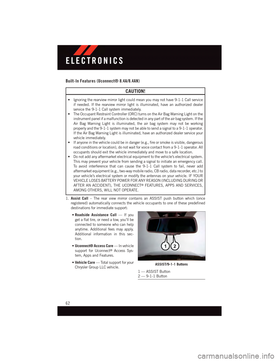
1.Assist Call–TherearviewmirrorcontainsanASSISTpushbuttonwhich(once
registered) automatically connects the vehicle occupants to one of these predefined
destinations for immediate support:
•Roadside Assistance Call—Ifyou
get a flat tire, or need a tow, you’ll be
connected to someone who can help
anytime. Additional fees may apply.
Additional information in this sec-
tion.
•Uconnect® Access Care—Invehicle
support for Uconnect®Access Sys-
tem, Apps and Features.
•Vehicle Care—Totalsupportforyour
Chrysler Group LLC vehicle.ASSIST/9-1-1 Buttons
1—ASSISTButton2—9-1-1Button
ELECTRONICS
62
Page 133 of 220
PROGRAMMABLE FEATURES
Uconnect® Customer Programmable Features
The Uconnect®system allows you to access Customer Programmable feature settings
such as Display, Clock, Safety/Assistance, Lights, Doors & Locks, Auto-On Comfort &
Remote Start, Engine Off Operation, Compass Settings, Audio, Trailer Brake,
Phone/Bluetooth®,SuspensionandSiriusXMSetupandSystemInformationthrough
buttons on the touchscreen.
NOTE:
If equipped with the Super Track Pak option please refer to the “Drive Mode Supplement”
within your Owners Information Kit for further descriptions of these modes.
•Pushthe“Controls”buttonlocatednearthebottomofthetouchscreen,thenpushthe
“Settings” button on the touchscreen to access the Settings screen. When making a
selection, scroll up or down until the preferred setting is highlighted, then press and
release the preferred setting until a check-mark appears next to the setting, showing
that setting has been selected. The following feature settings are available:
•Display•EngineOffOptions
•Units•Audio
•Voice•Phone/Bluetooth®
•Clock•SiriusXMSetup
•Safety&DrivingAssistance•RestoreSettings
•Lights•ClearPersonalData
•Doors&Locks•SystemInformation
•Auto-OnComfort&RemoteStart •Compass(5.0RadioOnly)
Refer to “Uconnect Settings/Customer Programmable Features” found within “Under-
standing Your Instrument Panel” located in your Owner's Manual on the DVD for further
information.
ELECTRONICS
131
Page 163 of 220
If the tire does not inflate to at least 26 psi (1.8 Bar) pressure within 15 minutes:
The tire is too badly damaged. Do not attempt to drive the vehicle further. Call for
assistance.
NOTE:
If the tire becomes over-inflated, press the Deflation Button to reduce the tire pressure to
the recommended inflation pressure before continuing.
If the tire inflates to the recommended pressure or is at least 26 psi (1.8 Bar) pressure
within 15 minutes:
1. Press the Power Button (4) to turn off the Tire Service Kit.
2. Remove the Speed Limit sticker from the top of the Sealant Bottle (1) and place the
sticker on the instrument panel.
3. Immediately disconnect the Sealant Hose (6) from the valve stem, reinstall the cap on
the fitting at the end of the hose, and place the Tire Service Kit in the vehicle storage
location. Quickly proceed to (D) “Drive Vehicle.”
(D) Drive Vehicle:
Immediately after injecting sealant and inflating the tire, drive the vehicle 5 miles (8 km)
or 10 minutes to ensure distribution of the Tire Service Kit Sealant within the tire. Do not
exceed 55 mph (88 km/h).
(E) After Driving:
Pull over to a safe location. Refer to “Whenever You Stop to Use Tire Service Kit” before
continuing.
1. Turn the Mode Select Knob (5) to the Air Mode position.
2. Uncoil the Air Pump Hose (7) (black in color) and screw the fitting at the end of hose
(7) onto the valve stem.
3. Uncoil the power plug and insert the plug into the vehicles 12 Volt power outlet.
4. Check the pressure in the tire by reading the Pressure Gauge (3).
If tire pressure is less than 19 psi (1.3 Bar), the tire is too badly damaged. Do not attempt
to drive the vehicle further. Call for assistance.
If the tire pressure is 19 psi (1.3 Bar) or higher:
1. Press the Power Button (4) to turn on Tire Service Kit and inflate the tire to the pressure
indicated on the tire and loading information label on the driver-side door opening.
2. Disconnect the Tire Service Kit from the valve stem, reinstall the cap on the valve stem
and unplug from 12 Volt outlet.
3. Place the Tire Service Kit in its proper storage area in the vehicle.
4. Have the tire inspected and repaired or replaced at the earliest opportunity at an
authorized dealer or tire service center.
WHAT TO DO IN EMERGENCIES
161