key DODGE CHALLENGER 2020 Owner's Manual
[x] Cancel search | Manufacturer: DODGE, Model Year: 2020, Model line: CHALLENGER, Model: DODGE CHALLENGER 2020Pages: 396, PDF Size: 16.64 MB
Page 57 of 396
GETTING TO KNOW YOUR VEHICLE55
(Continued)
Auto-Down Feature
The driver and, in some models, passenger
power window switches have an Auto-Down
feature. Push the window switch to the second
detent, release, and the window will go down
automatically.
To open the window part way, push the window
switch to the first detent and release it when
you want the window to stop. To stop the window from going all the way down
during the Auto-Down operation, pull up on the
switch briefly.
WIND BUFFETING
Wind buffeting can be described as the
perception of pressure on the ears or a
helicopter-type sound in the ears. Your vehicle
may exhibit wind buffeting with the windows
down, or the sunroof (if equipped) in certain
open or partially open positions. This is a normal
occurrence and can be minimized. If the
buffeting occurs with the rear windows open,
open the front and rear windows together to
minimize the buffeting. If the buffeting occurs
with the sunroof open, adjust the sunroof
opening to minimize the buffeting or open any
window.
POWER SUNROOF — IF EQUIPPED
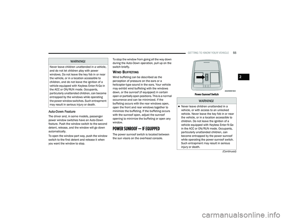
The power sunroof switch is located between
the sun visors on the overhead console.
Power Sunroof Switch
WARNING!
Never leave children unattended in a vehicle,
and do not let children play with power
windows. Do not leave the key fob in or near
the vehicle, or in a location accessible to
children, and do not leave the ignition of a
vehicle equipped with Keyless Enter-N-Go in
the ACC or ON/RUN mode. Occupants,
particularly unattended children, can become
entrapped by the windows while operating
the power window switches. Such entrapment
may result in serious injury or death.
WARNING!
Never leave children unattended in a
vehicle, or with access to an unlocked
vehicle. Never leave the key fob in or near
the vehicle, or in a location accessible to
children. Do not leave the ignition of a
vehicle equipped with Keyless Enter-N-Go
in the ACC or ON/RUN mode. Occupants,
particularly unattended children, can
become entrapped by the power sunroof
while operating the power sunroof switch.
Such entrapment may result in serious
injury or death.
2
20_LA_OM_EN_USC_t.book Page 55
Page 60 of 396
58GETTING TO KNOW YOUR VEHICLE
TRUNK
OPENING
The trunk can be opened from inside the vehicle
using the power trunk button located on the
instrument panel to the left of the steering
wheel.
The trunk lid can be released from outside the
vehicle by pushing the trunk button on the key
fob twice within five seconds or by using the
external release switch located on the
underside of the decklid overhang. The release
feature will function only when the vehicle is in
the unlock condition.
With the ignition in the ON/RUN position, the
trunk open symbol will display in the instrument
cluster indicating that the trunk is open. The
odometer display will reappear once the trunk is
closed. With the ignition in the OFF position, the trunk
open symbol will display until the trunk is
closed.
NOTE:
Refer to “Keyless Enter-N-Go — Passive Entry” in
”Doors” in this chapter for further information
on trunk operation with the Passive Entry
feature.
Opening From Inside The Vehicle
Interior Power Trunk Release
The trunk can be opened from inside
the vehicle using the power trunk
release button located on the
instrument panel to the left of the
steering wheel.
NOTE:
The automatic transmission must be in PARK
before the button will operate. For manual
transmissions, the vehicle must be in NEUTRAL.
Opening From Outside The Vehicle
To Unlock/Open The Trunk
The trunk may be unlocked/opened using
either of the following methods:
Key Fob Trunk Release Button
Passive Entry Button Key Fob Trunk Release Button
Push the power trunk button on the
key fob twice within five seconds to
release the trunk.
Passive Entry Button
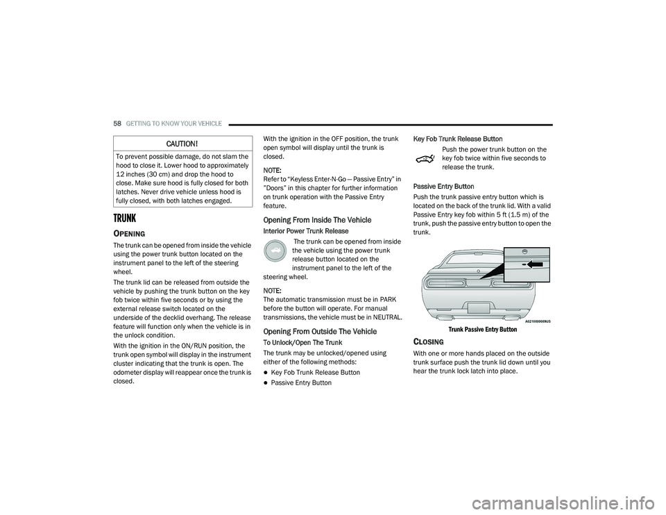
Push the trunk passive entry button which is
located on the back of the trunk lid. With a valid
Passive Entry key fob within 5 ft (1.5 m) of the
trunk, push the passive entry button to open the
trunk.
Trunk Passive Entry Button
CLOSING
With one or more hands placed on the outside
trunk surface push the trunk lid down until you
hear the trunk lock latch into place.
CAUTION!
To prevent possible damage, do not slam the
hood to close it. Lower hood to approximately
12 inches (30 cm) and drop the hood to
close. Make sure hood is fully closed for both
latches. Never drive vehicle unless hood is
fully closed, with both latches engaged.
20_LA_OM_EN_USC_t.book Page 58
Page 61 of 396
GETTING TO KNOW YOUR VEHICLE59
NOTE:
Before closing the trunk lid make sure your key
fob isn’t inside the trunk area. The trunk will
latch then automatically unlock if the key fob is
sensed, not allowing the key fob to be locked in
the trunk area.
TRUNK SAFETY
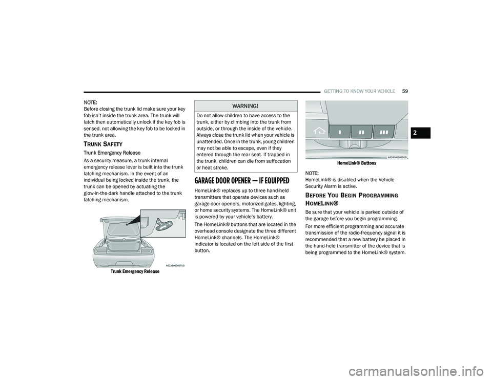
Trunk Emergency Release
As a security measure, a trunk internal
emergency release lever is built into the trunk
latching mechanism. In the event of an
individual being locked inside the trunk, the
trunk can be opened by actuating the
glow-in-the-dark handle attached to the trunk
latching mechanism.
Trunk Emergency Release
GARAGE DOOR OPENER — IF EQUIPPED
HomeLink® replaces up to three hand-held
transmitters that operate devices such as
garage door openers, motorized gates, lighting,
or home security systems. The HomeLink® unit
is powered by your vehicle’s battery.
The HomeLink® buttons that are located in the
overhead console designate the three different
HomeLink® channels. The HomeLink®
indicator is located on the left side of the first
button.
HomeLink® Buttons
NOTE:
HomeLink® is disabled when the Vehicle
Security Alarm is active.BEFORE YOU BEGIN PROGRAMMING
H
OMELINK®
Be sure that your vehicle is parked outside of
the garage before you begin programming.
For more efficient programming and accurate
transmission of the radio-frequency signal it is
recommended that a new battery be placed in
the hand-held transmitter of the device that is
being programmed to the HomeLink® system.
WARNING!
Do not allow children to have access to the
trunk, either by climbing into the trunk from
outside, or through the inside of the vehicle.
Always close the trunk lid when your vehicle is
unattended. Once in the trunk, young children
may not be able to escape, even if they
entered through the rear seat. If trapped in
the trunk, children can die from suffocation
or heat stroke.
2
20_LA_OM_EN_USC_t.book Page 59
Page 67 of 396
GETTING TO KNOW YOUR VEHICLE65
CUPHOLDERS
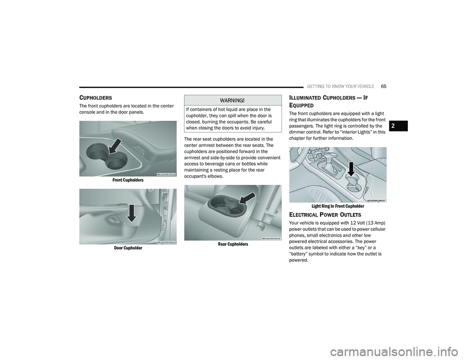
The front cupholders are located in the center
console and in the door panels.
Front CupholdersDoor Cupholder
The rear seat cupholders are located in the
center armrest between the rear seats. The
cupholders are positioned forward in the
armrest and side-by-side to provide convenient
access to beverage cans or bottles while
maintaining a resting place for the rear
occupant's elbows.
Rear Cupholders
ILLUMINATED CUPHOLDERS — IF
E
QUIPPED
The front cupholders are equipped with a light
ring that illuminates the cupholders for the front
passengers. The light ring is controlled by the
dimmer control. Refer to “Interior Lights” in this
chapter for further information.
Light Ring In Front Cupholder
ELECTRICAL POWER OUTLETS
Your vehicle is equipped with 12 Volt (13 Amp)
power outlets that can be used to power cellular
phones, small electronics and other low
powered electrical accessories. The power
outlets are labeled with either a “key” or a
“battery” symbol to indicate how the outlet is
powered.
WARNING!
If containers of hot liquid are place in the
cupholder, they can spill when the door is
closed, burning the occupants. Be careful
when closing the doors to avoid injury.
2
20_LA_OM_EN_USC_t.book Page 65
Page 68 of 396
66GETTING TO KNOW YOUR VEHICLE
Power outlets labeled with a “key” can be
powered when the ignition is in the ACC or ON/
RUN position, while the outlets labeled with a
“battery” are connected directly to the battery
and powered at all times.
These power outlets can also operate a
conventional cigar lighter unit.
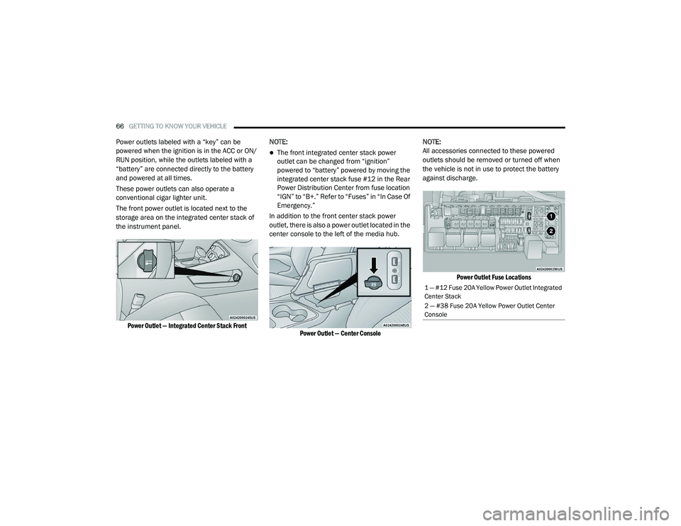
The front power outlet is located next to the
storage area on the integrated center stack of
the instrument panel.
Power Outlet — Integrated Center Stack Front
NOTE:
The front integrated center stack power
outlet can be changed from “ignition”
powered to “battery” powered by moving the
integrated center stack fuse #12 in the Rear
Power Distribution Center from fuse location
“IGN” to “B+.” Refer to “Fuses” in “In Case Of
Emergency.”
In addition to the front center stack power
outlet, there is also a power outlet located in the
center console to the left of the media hub.
Power Outlet — Center Console
NOTE:
All accessories connected to these powered
outlets should be removed or turned off when
the vehicle is not in use to protect the battery
against discharge.
Power Outlet Fuse Locations
1 — #12 Fuse 20A Yellow Power Outlet Integrated
Center Stack
2 — #38 Fuse 20A Yellow Power Outlet Center
Console
20_LA_OM_EN_USC_t.book Page 66
Page 72 of 396
70GETTING TO KNOW YOUR INSTRUMENT PANEL
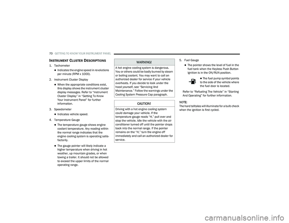
INSTRUMENT CLUSTER DESCRIPTIONS
1. Tachometer
Indicates the engine speed in revolutions
per minute (RPM x 1000).
2. Instrument Cluster Display
When the appropriate conditions exist,
this display shows the instrument cluster
display messages. Refer to “Instrument
Cluster Display” in “Getting To Know
Your Instrument Panel” for further
information.
3. Speedometer
Indicates vehicle speed.
4. Temperature Gauge
The temperature gauge shows engine
coolant temperature. Any reading within
the normal range indicates that the
engine cooling system is operating satis -
factorily.
The gauge pointer will likely indicate a
higher temperature when driving in hot
weather, up mountain grades, or when
towing a trailer. It should not be allowed
to exceed the upper limits of the normal
operating range. 5. Fuel Gauge
The pointer shows the level of fuel in the
fuel tank when the Keyless Push Button
Ignition is in the ON/RUN position.
The fuel pump symbol points
to the side of the vehicle where
the fuel door is located.
Refer to “Refueling The Vehicle” in “Starting
And Operating” for further information.
NOTE:
The hard telltales will illuminate for a bulb check
when the ignition is first cycled.
WARNING!
A hot engine cooling system is dangerous.
You or others could be badly burned by steam
or boiling coolant. You may want to call an
authorized dealer for service if your vehicle
overheats. If you decide to look under the
hood yourself, see “Servicing And
Maintenance.” Follow the warnings under the
Cooling System Pressure Cap paragraph.
CAUTION!
Driving with a hot engine cooling system
could damage your vehicle. If the
temperature gauge reads “H,” pull over and
stop the vehicle. Idle the vehicle with the air
conditioner turned off until the pointer drops
back into the normal range. If the pointer
remains on the “H,” turn the engine off
immediately and call an authorized dealer for
service.
20_LA_OM_EN_USC_t.book Page 70
Page 75 of 396
GETTING TO KNOW YOUR INSTRUMENT PANEL73
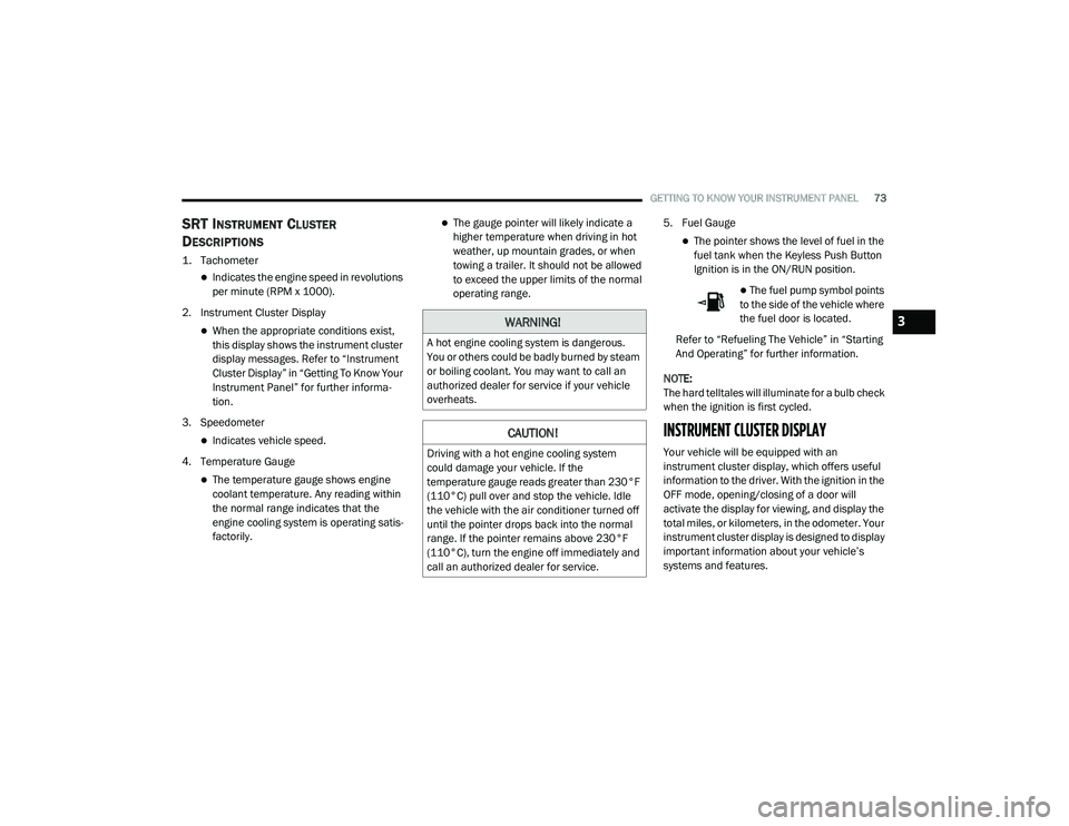
SRT INSTRUMENT CLUSTER
D
ESCRIPTIONS
1. Tachometer
Indicates the engine speed in revolutions
per minute (RPM x 1000).
2. Instrument Cluster Display
When the appropriate conditions exist,
this display shows the instrument cluster
display messages. Refer to “Instrument
Cluster Display” in “Getting To Know Your
Instrument Panel” for further informa -
tion.
3. Speedometer
Indicates vehicle speed.
4. Temperature Gauge
The temperature gauge shows engine
coolant temperature. Any reading within
the normal range indicates that the
engine cooling system is operating satis -
factorily.
The gauge pointer will likely indicate a
higher temperature when driving in hot
weather, up mountain grades, or when
towing a trailer. It should not be allowed
to exceed the upper limits of the normal
operating range. 5. Fuel Gauge
The pointer shows the level of fuel in the
fuel tank when the Keyless Push Button
Ignition is in the ON/RUN position.
The fuel pump symbol points
to the side of the vehicle where
the fuel door is located.
Refer to “Refueling The Vehicle” in “Starting
And Operating” for further information.
NOTE:
The hard telltales will illuminate for a bulb check
when the ignition is first cycled.
INSTRUMENT CLUSTER DISPLAY
Your vehicle will be equipped with an
instrument cluster display, which offers useful
information to the driver. With the ignition in the
OFF mode, opening/closing of a door will
activate the display for viewing, and display the
total miles, or kilometers, in the odometer. Your
instrument cluster display is designed to display
important information about your vehicle’s
systems and features.
WARNING!
A hot engine cooling system is dangerous.
You or others could be badly burned by steam
or boiling coolant. You may want to call an
authorized dealer for service if your vehicle
overheats.
CAUTION!
Driving with a hot engine cooling system
could damage your vehicle. If the
temperature gauge reads greater than 230°F
(110°C) pull over and stop the vehicle. Idle
the vehicle with the air conditioner turned off
until the pointer drops back into the normal
range. If the pointer remains above 230°F
(110°C), turn the engine off immediately and
call an authorized dealer for service.
3
20_LA_OM_EN_USC_t.book Page 73
Page 77 of 396
GETTING TO KNOW YOUR INSTRUMENT PANEL75
NOTE:
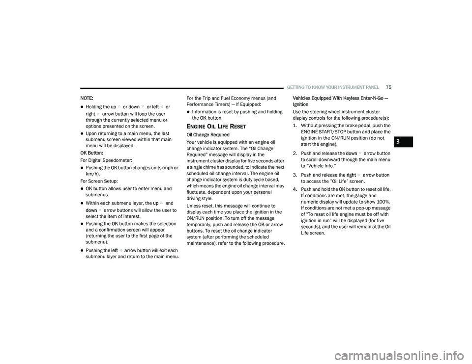
Holding the up or down or left or
right arrow button will loop the user
through the currently selected menu or
options presented on the screen.
Upon returning to a main menu, the last
submenu screen viewed within that main
menu will be displayed.
OK Button:
For Digital Speedometer:
Pushing the OK button changes units (mph or
km/h).
For Screen Setup:
OK button allows user to enter menu and
submenus.
Within each submenu layer, the up and
down arrow buttons will allow the user to
select the item of interest.
Pushing the OK button makes the selection
and a confirmation screen will appear
(returning the user to the first page of the
submenu).
Pushing the left arrow button will exit each
submenu layer and return to the main menu. For the Trip and Fuel Economy menus (and
Performance Timers) — If Equipped:
Information is reset by pushing and holding
the
OK button.
ENGINE OIL LIFE RESET
Oil Change Required
Your vehicle is equipped with an engine oil
change indicator system. The “Oil Change
Required” message will display in the
instrument cluster display for five seconds after
a single chime has sounded, to indicate the next
scheduled oil change interval. The engine oil
change indicator system is duty cycle based,
which means the engine oil change interval may
fluctuate, dependent upon your personal
driving style.
Unless reset, this message will continue to
display each time you place the ignition in the
ON/RUN position. To turn off the message
temporarily, push and release the OK or arrow
buttons. To reset the oil change indicator
system (after performing the scheduled
maintenance), refer to the following procedure. Vehicles Equipped With Keyless Enter-N-Go —
Ignition
Use the steering wheel instrument cluster
display controls for the following procedure(s):
1. Without pressing the brake pedal, push the
ENGINE START/STOP button and place the
ignition in the ON/RUN position (do not
start the engine).
2. Push and release the down arrow button
to scroll downward through the main menu
to “Vehicle Info.”
3. Push and release the right arrow button
to access the ”Oil Life” screen.
4. Push and hold the OK button to reset oil life.
If conditions are met, the gauge and
numeric display will update to show 100%.
If conditions are not met a pop-up message
of "To reset oil life engine must be off with
ignition in run” will be displayed (for five
seconds), and the user will remain at the Oil
Life screen.
3
20_LA_OM_EN_USC_t.book Page 75
Page 112 of 396
110SAFETY
Vehicles With Compact Spare
1. The compact spare tire or non-matching
full size does not have a Tire Pressure
Monitoring sensor. Therefore, the TPMS
will not monitor the pressure in the
compact or non-matching full size spare
tire.
2. If you install the compact or non-matching full size spare tire in place of a road tire that
has a pressure below the low-pressure
warning limit, upon the next ignition key
cycle, the TPMS Warning Light will remain
on and a chime will sound. In addition, the
graphic in the instrument cluster will still
display a different color pressure value and
an "Inflate to XX" message.
3. After driving the vehicle for up to 20 minutes above 15 mph (24 km/h), the
TPMS Warning Light will flash on and off for
75 seconds and then remain on solid. In
addition, the instrument cluster will display
a “Service Tire Pressure System” message
for five seconds and then display dashes
(- -) in place of the pressure value. 4. For each subsequent ignition key cycle, a
chime will sound, the TPMS Warning Light
will flash on and off for 75 seconds and then
remain on solid, and the instrument cluster
will display a “Service Tire Pressure System”
message for five seconds and then display
dashes (- -) in place of the pressure value.
5. Once you repair or replace the original road tire and reinstall it on the vehicle in place of
the compact spare or non-matching full
size, the TPMS will update automatically. In
addition, the TPMS Warning Light will turn
off and the graphic in the instrument cluster
will display a new pressure value instead of
dashes (- -), as long as no tire pressure is
below the low-pressure warning limit in any
of the four active road tires. The vehicle may
need to be driven for up to 20 minutes
above 15 mph (24 km/h) in order for the
TPMS to receive this information.
TPMS Deactivation — If Equipped
The Tire Pressure Monitoring System (TPMS)
can be deactivated if replacing all four wheel
and tire assemblies (road tires) with wheel and
tire assemblies that do not have TPMS sensors,
such as when installing winter wheel and tire
assemblies on your vehicle. To deactivate the TPMS, first replace all four
wheel and tire assemblies (road tires) with tires
not equipped with Tire Pressure Monitoring
(TPM) sensors. Then, drive the vehicle for
20 minutes above 15 mph (24 km/h). The
TPMS will chime, the TPMS Warning Light will
flash on and off for 75 seconds and then remain
on. The instrument cluster will display the
“Service Tire Pressure System” message and
then display dashes (--) in place of the pressure
values.
Beginning with the next ignition cycle, the TPMS
will no longer chime or display the “Service Tire
Pressure System” message in the instrument
cluster but dashes (--) will remain in place of the
pressure values.
To reactivate the TPMS, replace all four wheel
and tire assemblies (road tires) with tires
equipped with TPM sensors. Then, drive the
vehicle for up to 20 minutes above 15 mph
(24 km/h). The TPMS will chime, the TPMS
Warning Light will flash on and off for
75 seconds and then turn off. The instrument
cluster will display the “Service Tire Pressure
System” message and then display pressure
values in place of the dashes.
20_LA_OM_EN_USC_t.book Page 110
Page 130 of 396
128SAFETY
(Continued)
Enhanced Accident Response System
In the event of an impact, if the communication
network remains intact, and the power remains
intact, depending on the nature of the event,
the ORC will determine whether to have the
Enhanced Accident Response System perform
the following functions:
Cut off fuel to the engine (if equipped).
Cut off battery power to the electric motor
(if equipped).
Flash hazard lights as long as the battery has
power.
Turn on the interior lights, which remain on
as long as the battery has power or for
15 minutes from the intervention of the
Enhanced Accident Response System.
Unlock the power door locks.
Your vehicle may also be designed to perform
any of these other functions in response to the
Enhanced Accident Response System:
Turn off the Fuel Filter Heater, Turn off the
HVAC Blower Motor, Close the HVAC Circula -
tion Door
Cut off battery power to the:
Engine
Electric Motor (if equipped)
Electric power steering
Brake booster
Electric park brake
Automatic transmission gear selector
Horn
Front wiper
Headlamp washer pump
NOTE:
After an accident, remember to cycle the igni -
tion to the STOP (OFF/LOCK) position and
remove the key from the ignition switch to avoid
draining the battery. Carefully check the vehicle
for fuel leaks in the engine compartment and on
the ground near the engine compartment and
fuel tank before resetting the system and
starting the engine. If there are no fuel leaks or
damage to the vehicle electrical devices (e.g.
headlights) after an accident, reset the system
by following the procedure described below. If
you have any doubt, contact an authorized
dealer.
Enhanced Accident Response System
Reset Procedure
In order to reset the Enhanced Accident
Response System functions after an event, the
ignition switch must be changed from ignition
START or ON/RUN to ignition OFF. Carefully
check the vehicle for fuel leaks in the engine
compartment and on the ground near the
engine compartment and fuel tank before
resetting the system and starting the engine.
Maintaining Your Air Bag System
WARNING!
Modifications to any part of the air bag
system could cause it to fail when you need
it. You could be injured if the air bag system
is not there to protect you. Do not modify
the components or wiring, including adding
any kind of badges or stickers to the
steering wheel hub trim cover or the upper
passenger side of the instrument panel. Do
not modify the front bumper, vehicle body
structure, or add aftermarket side steps or
running boards.
20_LA_OM_EN_USC_t.book Page 128