interior lights DODGE CHALLENGER 2021 Owners Manual
[x] Cancel search | Manufacturer: DODGE, Model Year: 2021, Model line: CHALLENGER, Model: DODGE CHALLENGER 2021Pages: 328, PDF Size: 15 MB
Page 5 of 328
3
Programming HomeLink® To A Garage Door
Opener ..............................................................39
Programming HomeLink® To A Miscellaneous
Device ...............................................................40
Reprogramming A Single HomeLink® Button .. 40
Canadian/Gate Operator Programming .........40
EXTERIOR LIGHTS.................................................. 41
Headlight Switch...............................................41
Multifunction Lever ..........................................42
Daytime Running Lights (DRLs) —
If Equipped........................................................42
High/Low Beam Switch....................................42
Automatic High Beam Headlamp Control —
If Equipped .......................................................42
Flash-To-Pass....................................................43
Automatic Headlights ......................................43
Parking Lights ..................................................43
Automatic Headlights With Wipers..................43
Headlight Time Delay ......................................43
Lights-On Reminder .........................................43
Fog Lights — If Equipped ..................................44
Turn Signals .....................................................44
Lane Change Assist — If Equipped ..................44
INTERIOR LIGHTS ................................................. 44
Front Map/Reading Lights ..............................45
Ambient Light — If Equipped ............................45
Dimmer Control ................................................45 WINDSHIELD WIPERS AND WASHERS............... 46
Windshield Wiper Operation ............................46
Rain Sensing Wipers — If Equipped ................47
CLIMATE CONTROLS .............................................48
Automatic Climate Control Descriptions
And Functions ..................................................48
Automatic Temperature Control (ATC) ...........51
Climate — Voice Recognition ...........................51
Operating Tips .................................................51
INTERIOR STORAGE AND EQUIPMENT ............... 53
Storage..............................................................53
Illuminated Cupholders — If Equipped............53
USB/AUX Control ..............................................54
Power Outlets ...................................................54
WINDOWS ..............................................................56
Power Window Controls ...................................56
Wind Buffeting ..................................................56
POWER SUNROOF — IF EQUIPPED ...................... 56
Opening And Closing The Sunroof...................57
Pinch Protect Feature — If Equipped ..............57
Venting Sunroof................................................57
Sunshade Operation ........................................57
Sunroof Maintenance ......................................58
Ignition Off Operation.......................................58 HOOD....................................................................... 58
Opening The Hood ..........................................58
Closing The Hood ............................................. 58
TRUNK ..................................................................... 59
Opening The Trunk ........................................... 59
Closing The Trunk............................................. 59
Trunk Safety ..................................................... 60
GETTING TO KNOW YOUR
INSTRUMENT PANEL
INSTRUMENT CLUSTER ........................................ 61Instrument Cluster Descriptions ..................... 62
INSTRUMENT CLUSTER DISPLAY ........................ 62
Location And Controls...................................... 63
Engine Oil Life Reset ........................................ 64
Performance Shift Indicator (PSI) —
If Equipped .......................................................64
Instrument Cluster Display Selectable
Menu Items ...................................................... 64
Battery Saver On/Battery Saver Mode
Message — Electrical Load Reduction
Actions — If Equipped ..................................... 68
21_LA_OM_EN_USC_t.book Page 3
Page 12 of 328
10
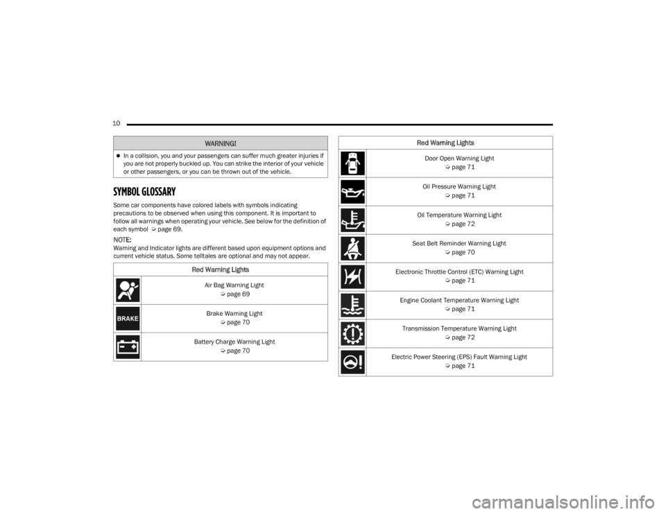
SYMBOL GLOSSARY
Some car components have colored labels with symbols indicating
precautions to be observed when using this component. It is important to
follow all warnings when operating your vehicle. See below for the definition of
each symbol Úpage 69.
NOTE:Warning and Indicator lights are different based upon equipment options and
current vehicle status. Some telltales are optional and may not appear.
In a collision, you and your passengers can suffer much greater injuries if
you are not properly buckled up. You can strike the interior of your vehicle
or other passengers, or you can be thrown out of the vehicle.
Red Warning Lights
Air Bag Warning Light
Úpage 69
Brake Warning Light Úpage 70
Battery Charge Warning Light Úpage 70
WARNING!
Door Open Warning Light
Úpage 71
Oil Pressure Warning Light Úpage 71
Oil Temperature Warning Light Úpage 72
Seat Belt Reminder Warning Light Úpage 70
Electronic Throttle Control (ETC) Warning Light Úpage 71
Engine Coolant Temperature Warning Light Úpage 71
Transmission Temperature Warning Light Úpage 72
Electric Power Steering (EPS) Fault Warning Light Úpage 71
Red Warning Lights
21_LA_OM_EN_USC_t.book Page 10
Page 43 of 328
GETTING TO KNOW YOUR VEHICLE41
NOTE:
If the indicator light stays on constantly,
programming is complete and the garage
door/device should activate when the
HomeLink® button is pressed.
To program the two remaining HomeLink®
buttons, repeat each step for each
remaining button. DO NOT erase the chan -
nels.
If you unplugged the garage door opener/device
for programming, plug it back in at this time.
Reprogramming A Single HomeLink® Button
(Canadian/Gate Operator)
To reprogram a channel that has been previously
trained, follow these steps:
1. Place the ignition in the ON/RUN position.
2. Press and hold the desired HomeLink® button until the indicator light begins to flash after 20
seconds. Do not release the button.
3. Without releasing the button, proceed with “Canadian/Gate Operator Programming” step
2 and follow all remaining steps.
EXTERIOR LIGHTS
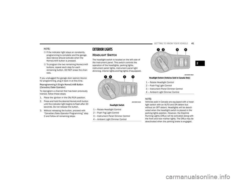
HEADLIGHT SWITCH
The headlight switch is located on the left side of
the instrument panel. This switch controls the
operation of the headlights, parking lights,
instrument panel lights, instrument panel light
dimming, interior lights and fog lights (if equipped).
Headlight Switch Headlight Switch (Vehicles Sold In Canada Only)
NOTE:Vehicles sold in Canada are equipped with a head
-
light switch with an AUTO and ON detent but
without an OFF detent. Headlights will be deacti -
vated when the headlight switch is placed in the
parking lights position. However, the Daytime
Running Lights (DRLs) will be activated along with
the front and rear marker lights. The DRLs may be
deactivated when the parking brake is engaged.
1 — Rotate Headlight Control
2 — Push Fog Light Control
3 — Instrument Panel Dimmer Control
4 — Ambient Light Dimmer Control
1 — Rotate Headlight Control
2 — Push Fog Light Control
3 — Instrument Panel Dimmer Control
4 — Ambient Light Dimmer Control
2
21_LA_OM_EN_USC_t.book Page 41
Page 46 of 328
44GETTING TO KNOW YOUR VEHICLE
FOG LIGHTS — IF EQUIPPED
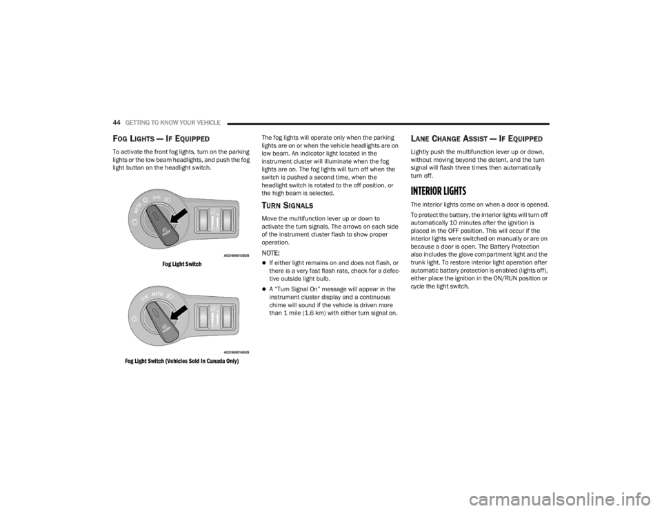
To activate the front fog lights, turn on the parking
lights or the low beam headlights, and push the fog
light button on the headlight switch.
Fog Light Switch
Fog Light Switch (Vehicles Sold In Canada Only)
The fog lights will operate only when the parking
lights are on or when the vehicle headlights are on
low beam. An indicator light located in the
instrument cluster will illuminate when the fog
lights are on. The fog lights will turn off when the
switch is pushed a second time, when the
headlight switch is rotated to the off position, or
the high beam is selected.
TURN SIGNALS
Move the multifunction lever up or down to
activate the turn signals. The arrows on each side
of the instrument cluster flash to show proper
operation.
NOTE:
If either light remains on and does not flash, or
there is a very fast flash rate, check for a defec
-
tive outside light bulb.
A “Turn Signal On” message will appear in the
instrument cluster display and a continuous
chime will sound if the vehicle is driven more
than 1 mile (1.6 km) with either turn signal on.
LANE CHANGE ASSIST — IF EQUIPPED
Lightly push the multifunction lever up or down,
without moving beyond the detent, and the turn
signal will flash three times then automatically
turn off.
INTERIOR LIGHTS
The interior lights come on when a door is opened.
To protect the battery, the interior lights will turn off
automatically 10 minutes after the ignition is
placed in the OFF position. This will occur if the
interior lights were switched on manually or are on
because a door is open. The Battery Protection
also includes the glove compartment light and the
trunk light. To restore interior light operation after
automatic battery protection is enabled (lights off),
either place the ignition in the ON/RUN position or
cycle the light switch.
21_LA_OM_EN_USC_t.book Page 44
Page 48 of 328
46GETTING TO KNOW YOUR VEHICLE
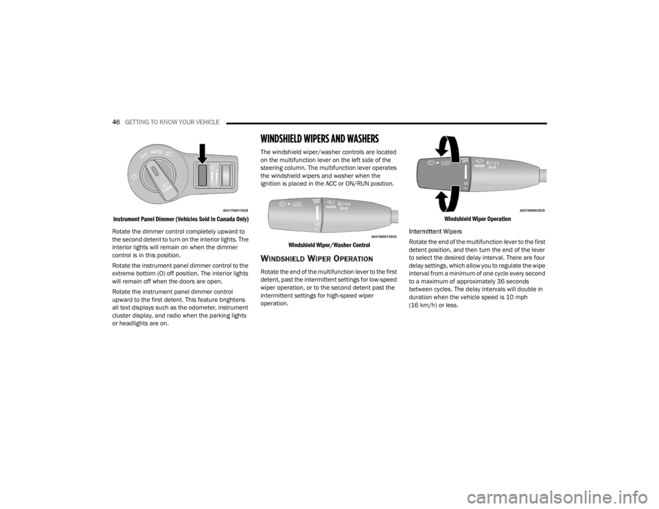
Instrument Panel Dimmer (Vehicles Sold In Canada Only)
Rotate the dimmer control completely upward to
the second detent to turn on the interior lights. The
interior lights will remain on when the dimmer
control is in this position.
Rotate the instrument panel dimmer control to the
extreme bottom (O) off position. The interior lights
will remain off when the doors are open.
Rotate the instrument panel dimmer control
upward to the first detent. This feature brightens
all text displays such as the odometer, instrument
cluster display, and radio when the parking lights
or headlights are on.
WINDSHIELD WIPERS AND WASHERS
The windshield wiper/washer controls are located
on the multifunction lever on the left side of the
steering column. The multifunction lever operates
the windshield wipers and washer when the
ignition is placed in the ACC or ON/RUN position.
Windshield Wiper/Washer Control
WINDSHIELD WIPER OPERATION
Rotate the end of the multifunction lever to the first
detent, past the intermittent settings for low-speed
wiper operation, or to the second detent past the
intermittent settings for high-speed wiper
operation.
Windshield Wiper Operation
Intermittent Wipers
Rotate the end of the multifunction lever to the first
detent position, and then turn the end of the lever
to select the desired delay interval. There are four
delay settings, which allow you to regulate the wipe
interval from a minimum of one cycle every second
to a maximum of approximately 36 seconds
between cycles. The delay intervals will double in
duration when the vehicle speed is 10 mph
(16 km/h) or less.
21_LA_OM_EN_USC_t.book Page 46
Page 71 of 328
GETTING TO KNOW YOUR INSTRUMENT PANEL69
Turning on all possible vehicle electrical loads
(e.g. HVAC to max settings, exterior and interior
lights, overloaded power outlets +12 Volts,
115 Volts AC, USB ports) during certain driving
conditions (city driving, towing, frequent stop-
ping).
Installing options like additional lights, upfitter
electrical accessories, audio systems, alarms
and similar devices.
Unusual driving cycles (short trips separated by
long parking periods).
The vehicle was parked for an extended period
of time (weeks, months).
The battery was recently replaced and was not
charged completely.
The battery was discharged by an electrical load
left on when the vehicle was parked.
The battery was used for an extended period
with the engine not running to supply radio,
lights, chargers, +12 Volts portable appliances
like vacuum cleaners, game consoles and
similar devices. What to do when an electrical load reduction
action message is present (“Battery Saver On” or
“Battery Saver Mode”)
During a trip:
Reduce power to unnecessary loads if possible:
Turn off redundant lights (interior or exterior)
Check what may be plugged in to power
outlets +12 Volts, 115 Volts AC, USB ports
Check HVAC settings (blower, temperature)
Check the audio settings (volume)
After a trip:
Check if any aftermarket equipment was
installed (additional lights, upfitter electrical
accessories, audio systems, alarms) and review
specifications if any (load and Ignition Off Draw
currents).
Evaluate the latest driving cycles (distance,
driving time and parking time).
The vehicle should have service performed if
the message is still present during consecutive
trips and the evaluation of the vehicle and
driving pattern did not help to identify the cause.
WARNING LIGHTS AND MESSAGES
The warning/indicator lights will illuminate in the
instrument panel together with a dedicated
message and/or acoustic signal when applicable.
These indications are indicative and precautionary
and as such must not be considered as exhaustive
and/or alternative to the information contained in
the Owner’s Manual, which you are advised to read
carefully in all cases. Always refer to the
information in this chapter in the event of a failure
indication. All active telltales will display first if
applicable. The system check menu may appear
different based upon equipment options and
current vehicle status. Some telltales are optional
and may not appear.
RED WARNING LIGHTS
Air Bag Warning Light
This warning light will illuminate to
indicate a fault with the air bag, and will
turn on for four to eight seconds as a
bulb check when the ignition is placed in
the ON/RUN or ACC/ON/RUN position. This light
will illuminate with a single chime when a fault with
the air bag has been detected, it will stay on until
the fault is cleared. If the light is either not on
during startup, stays on, or turns on while driving,
have the system inspected at an authorized dealer
as soon as possible.
3
21_LA_OM_EN_USC_t.book Page 69
Page 129 of 328

MULTIMEDIA127
Lights
When the Lights button is pressed on the touchscreen, the system displays the options related to the vehicle’s exterior and interior lights.
NOTE:When the “Daytime Running Lights” feature is selected, the daytime running lights can be turned On or Off. This feature is only allowed by law in the country
of the vehicle purchased.
Depending on the vehicle’s options, feature settings may vary.
Setting Name Description
Headlight Off DelayThis setting will allow you to set the amount of time it takes for the headlights
to shut off after the vehicle is turned off. The available settings are “0 sec”, “30 sec”, “60 sec”, and “90 sec”.
Headlight Illumination On Approach This setting will allow you to set the amount of time it takes for the headlights
to shut off after the vehicle is unlocked. The available settings are “0 sec”, “30 sec”, “60 sec”, and “90 sec”.
Headlights with Wipers This setting will turn the headlights on when the wipers are activated.
Daytime Running Lights This setting will allow you to turn the Daytime Running Lights on or off.
Flash Lights With Lock This setting will allow you to turn on or off the flashing of the lights when the
Lock button is pushed on the key fob. Available settings are “On” and “Off”.
Auto Dim High Beams This setting will allow you to turn the Auto Dim High Beams on or off.5
21_LA_OM_EN_USC_t.book Page 127
Page 208 of 328
206SAFETY
If A Deployment Occurs
The front air bags are designed to deflate
immediately after deployment.
NOTE:Front and/or side air bags will not deploy in all colli -
sions. This does not mean something is wrong with
the air bag system.
If you do have a collision which deploys the air
bags, any or all of the following may occur:
The air bag material may sometimes cause
abrasions and/or skin reddening to the occu -
pants as the air bags deploy and unfold. The
abrasions are similar to friction rope burns or
those you might get sliding along a carpet or
gymnasium floor. They are not caused by
contact with chemicals. They are not perma-
nent and normally heal quickly. However, if you
haven’t healed significantly within a few days,
or if you have any blistering, see your doctor
immediately.
As the air bags deflate, you may see some
smoke-like particles. The particles are a normal
by-product of the process that generates the
non-toxic gas used for air bag inflation. These
airborne particles may irritate the skin, eyes,
nose, or throat. If you have skin or eye irritation,
rinse the area with cool water. For nose or throat
irritation, move to fresh air. If the irritation
continues, see your doctor. If these particles settle on your clothing, follow the garment
manufacturer’s instructions for cleaning.
Do not drive your vehicle after the air bags have
deployed. If you are involved in another collision,
the air bags will not be in place to protect you.
NOTE:
Air bag covers may not be obvious in the interior
trim, but they will open during air bag deploy -
ment.
After any collision, the vehicle should be taken
to an authorized dealer immediately.
Enhanced Accident Response System
In the event of an impact, if the communication
network remains intact, and the power remains
intact, depending on the nature of the event, the
Occupant Restraint Controller (ORC) will determine
whether to have the Enhanced Accident Response
System perform the following functions:
Cut off fuel to the engine (if equipped).
Cut off battery power to the electric motor (if
equipped).
Flash hazard lights as long as the battery has
power.
Turn on the interior lights, which remain on as
long as the battery has power or for 15 minutes
from the intervention of the Enhanced Accident
Response System.
Unlock the power door locks.
Your vehicle may also be designed to perform any
of these other functions in response to the
Enhanced Accident Response System:
Turn off the Fuel Filter Heater, Turn off the HVAC
Blower Motor, Close the HVAC Circulation Door
Cut off battery power to the:
Engine
Electric Motor (if equipped)
Electric power steering
Brake booster
Electric park brake
Automatic transmission gear selector
Horn
Front wiper
Headlamp washer pump
WARNING!
Deployed air bags and seat belt pretensioners
cannot protect you in another collision. Have the
air bags, seat belt pretensioners, and the seat
belt retractor assemblies replaced by an
authorized dealer immediately. Also, have the
Occupant Restraint Controller System serviced
as well.
21_LA_OM_EN_USC_t.book Page 206
Page 248 of 328
246
SERVICING AND MAINTENANCE
SCHEDULED SERVICING
3.6L AND 5.7L ENGINES
These engines are equipped with an automatic oil
change indicator system. The oil change indicator
system will remind you that it is time to take your
vehicle in for scheduled maintenance.
Based on engine operation conditions, the oil
change indicator message will illuminate. This
means that service is required for the vehicle.
Operating conditions such as frequent short-trips,
trailer tow, and extremely hot or cold ambient
temperatures will influence when the “Change Oil”
or “Oil Change Required” message is displayed.
Have your vehicle serviced as soon as possible,
within the next 500 miles (805 km).The “Oil Change Required” message will be
displayed in the instrument cluster and a single
chime will sound, indicating that an oil change is
necessary.
An authorized dealer will reset the oil change
indicator message after completing the scheduled
oil change.
NOTE:Under no circumstances should oil change
intervals exceed 10,000 miles (16,000 km),
12 months or 350 hours of engine run time,
whichever comes first. The 350 hours of engine
run or idle time is generally only a concern for fleet
customers.
Once A Month Or Before A Long Trip:
Check engine oil level.
Check windshield washer fluid level.
Check tire pressure and look for unusual wear
or damage. Rotate tires at the first sign of irreg
-
ular wear, even if it occurs before your next
scheduled service.
Check the fluid levels of the coolant reservoir,
brake master cylinder, and power steering (if
equipped) and fill as needed.
Check function of all interior and exterior lights.
21_LA_OM_EN_USC_t.book Page 246
Page 315 of 328

313
Autostick Operation
.................................................... 91Axle Fluid....................................................... 307Axle Lubrication............................................. 307
B
Back-Up......................................................... 108Battery.................................................... 70, 254Charging System Light................................. 70Keyless Key Fob Replacement.................... 14Location.................................................... 254Belts, Seat..................................................... 223Blind Spot Monitoring.................................... 184BluetoothConnecting To A Particular Mobile Phone Or Audio Device After Pairing
................154Body Mechanism Lubrication........................ 260B-Pillar Location............................................. 285Brake Assist System...................................... 179Brake Control System.................................... 179Brake Fluid.......................................... 265, 307Brake System...................................... 265, 301Fluid Check..................................... 265, 307Master Cylinder......................................... 265Parking........................................................ 82Warning Light..................................... 70, 301
Brake/Transmission Interlock......................... 87Break-In Recommendations, New Vehicle....... 82Brightness, Interior Lights................................ 45Bulb Replacement........................................ 276Bulbs, Light.......................................... 225, 276
C
Camera, Rear................................................ 108Capacities, Fluid........................................... 305Caps, FillerFuel.......................................................... 109Oil (Engine)............................................... 251Radiator (Coolant Pressure)..................... 264Car Washes................................................... 298Carbon Monoxide Warning............................ 225CargoVehicle Loading........................................ 110CD................................................................. 148Cellular Phone.............................................. 177Certification Label......................................... 110Chains, Tire................................................... 295Chart, Tire Sizing........................................... 281Check Engine Light
(Malfunction Indicator Light)............................ 77Checking Your Vehicle For Safety................. 223Checks, Safety.............................................. 223Child Restraint.............................................. 208
Child RestraintsBooster Seats........................................... 211Child Seat Installation............................... 221How To Stow An unused ALR Seat Belt..... 217Infant And Child Restraints....................... 210Lower Anchors And Tethers For Children.. 213Older Children And Child Restraints.......... 210Seating Positions...................................... 212Clean Air Gasoline......................................... 303CleaningWheels...................................................... 294Climate Control................................................48Cold Weather Operation...................................81Compact Spare Tire...................................... 292Contract, Service........................................... 309Controls........................................................ 140Cooling Pressure Cap (Radiator Cap)............ 264Cooling System............................................. 262Adding Coolant (Antifreeze)...................... 263Coolant Level................................... 262, 264Cooling Capacity....................................... 305Disposal Of Used Coolant......................... 264Drain, Flush, And Refill............................. 262Inspection................................................. 264Points To Remember................................ 264Pressure Cap............................................ 264Radiator Cap............................................. 264Selection Of Coolant (Antifreeze)......................... 263, 305, 306
11
21_LA_OM_EN_USC_t.book Page 313