radio DODGE CHALLENGER 2021 Owners Manual
[x] Cancel search | Manufacturer: DODGE, Model Year: 2021, Model line: CHALLENGER, Model: DODGE CHALLENGER 2021Pages: 328, PDF Size: 15 MB
Page 2 of 328

The driver’s primary responsibility is the safe operation of the vehicle. Driving w\
hile distracted can result in loss of vehicle control, resulting in an accident and
personal injury. FCA US LLC strongly recommends that the driver use extreme caution whe\
n using any device or feature that may take their attention off the road.
Use of any electrical devices, such as cellular telephones, computers, p\
ortable radios, vehicle navigation or other devices, by the driver while the vehicle is moving
is dangerous and could lead to a serious accident. Texting while driving is also dangerous and should never be done while th\
e vehicle is moving. If you find yourself
unable to devote your full attention to vehicle operation, pull off the \
road to a safe location and stop your vehicle. Some states or provinces prohibit the use of
cellular telephones or texting while driving. It is always the driver’\
s responsibility to comply with all local laws.
This Owner’s Manual has been prepared to help you get acquainted with your new Dodg\
e brand vehicle and to provide a convenient reference source
for common questions.
Not all features shown in this manual may apply to your vehicle. For add\
itional information, visit www.mopar.com (U.S.), www.mopar.ca (Canada) or your local
Dodge brand dealer.
Drunk driving is one of the most frequent causes of accidents. Your driving ability can be seriously impaired with blood alcohol levels
far below the legal minimum. If you are drinking, don’t drive. Ride with a designated non-drinking driver, call a cab, a friend or use
public transportation.
DRIVING AND ALCOHOL
Driving after drinking can lead to an accident. Your perceptions are less sharp, your reflexes are slower and your judg\
ment is impaired
when you have been drinking. Never drink and then drive.
WARNING!
WARNING: Operating, servicing and maintaining a passenger vehicle or off-highway \
motor vehicle can expose you to
chemicals including engine exhaust, carbon monoxide, phthalates, and lea\
d, which are known to the State of California to
cause cancer and birth defects or other reproductive harm. To minimize exposure, avoid breathing exhaust, do not idle the
engine except as necessary, service your vehicle in a well-ventilated area and wear gloves or wash\
your hands frequently when
servicing your vehicle. For more information go to
www.P65Warnings.ca.gov/passenger-vehicle.
This Owner’s Manual illustrates and describes the operation of features and equipment that are either standard or optional on this vehicle. This manual m\
ay also include
a description of features and equipment that are no longer available or \
were not ordered on this vehicle. Please disregard any features and equipment desc\
ribed in this
manual that are not on this vehicle. FCA US LLC reserves the right to ma\
ke changes in design and specifications, and/or make additions to or improvemen\
ts to its products
without imposing any obligation upon itself to install them on products \
previously manufactured.
With respect to any vehicles sold in Canada, the name FCA US LLC shall b\
e deemed to be deleted and the name FCA Canada Inc. used in substitution theref\
ore.
This Owner’s Manual is intended to familiarize you with the important features of your vehicle. Your most up-to-date Owner’s Manual, Navigation/Uconnect manuals and
Warranty Booklet can be found by visiting the website on the back cover.
U.S. Residents: If you are the first registered retail owner of your vehicle, you ma\
y obtain a complimentary printed copy of the Warranty Booklet by calling 1-800-423-6343
or by contacting your dealer. Replacement kits can be purchased by visiting www.techauthority.com.
Canadian Residents: If you are the first registered retail owner of your vehicle, you ma\
y obtain a complimentary printed copy of the Warranty Booklet or purchase a
replacement kit by calling 1-800-387-1143 or by contacting your dealer.
Page 7 of 328
5
TRAILER TOWING ............................................... 111 Common Towing Definitions ......................... 111Trailer Hitch Classification ............................ 113
Trailer Towing Weights (Maximum Trailer
Weight Ratings) ............................................. 113
Trailer And Tongue Weight ........................... 114
Towing Requirements ................................... 114Towing Tips ................................................... 116
RECREATIONAL TOWING
(BEHIND MOTORHOME) ..................................... 117
DRIVING TIPS ....................................................... 117
Driving On Slippery Surfaces ........................ 117
Driving Through Water ................................. 118
MULTIMEDIA
UCONNECT SYSTEMS ......................................... 119
CYBERSECURITY ................................................. 119
UCONNECT SETTINGS ........................................ 120Customer Programmable Features .............. 120
UCONNECT INTRODUCTION................................ 135
System Overview .......................................... 135
Drag & Drop Menu Bar ................................. 138Safety And General Information ................... 138
UCONNECT MODES ............................................. 139
Steering Wheel Audio Controls ..................... 139
Radio Mode .................................................. 140
Media Mode .................................................. 148
Phone Mode ................................................. 150 ANDROID AUTO™ & APPLE CARPLAY® —
IF EQUIPPED ........................................................ 161
Android Auto™ .............................................. 161
Apple CarPlay® ............................................. 163Android Auto™ And Apple CarPlay®
Tips And Tricks .............................................. 165
PERFORMANCE PAGES...................................... 165
Home.............................................................. 166
Timers ............................................................ 168
Gauges ........................................................... 170
G-Force........................................................... 171
Engine ............................................................ 172
Dynamometer (Dyno) .................................... 172
DODGE DRIVE MODES — IF EQUIPPED ............ 173
Performance Control — If Equipped ............. 173
RADIO OPERATION AND MOBILE PHONES ..... 177
Regulatory And Safety Information .............. 177
SAFETY
SAFETY FEATURES .............................................. 178 Anti-Lock Brake System (ABS) ..................... 178
Electronic Brake Control (EBC) System ...... 179
AUXILIARY DRIVING SYSTEMS.......................... 184
Blind Spot Monitoring (BSM) —
If Equipped..................................................... 184Forward Collision Warning (FCW) Operation —
If Equipped..................................................... 187Tire Pressure Monitoring System (TPMS) .... 189 OCCUPANT RESTRAINT SYSTEMS ................... 192
Occupant Restraint Systems Features ....... 192
Important Safety Precautions ...................... 192
Seat Belt Systems ........................................ 193
Supplemental Restraint Systems (SRS) ...... 199Child Restraints ............................................ 208
SAFETY TIPS ........................................................ 223
Transporting Passengers.............................. 223
Transporting Pets ......................................... 223
Safety Checks You Should Make Inside
The Vehicle ................................................... 223
Periodic Safety Checks You Should Make
Outside The Vehicle ...................................... 225
Exhaust Gas................................................... 225
Carbon Monoxide Warnings ......................... 225
IN CASE OF EMERGENCY
HAZARD WARNING FLASHERS ......................... 226
ASSIST AND SOS MIRROR — IF EQUIPPED...... 226
JACKING AND TIRE CHANGING ......................... 229 Preparations For Jacking .............................. 230
Jack Location/Spare Tire Stowage ............. 230
Jacking And Changing A Tire ....................... 231
TIRE SERVICE KIT — IF EQUIPPED ..................... 234
Tire Service Kit Storage ................................ 234
Tire Service Kit Components And Operation ...234
Tire Service Kit Usage Precautions .............. 235
Sealing A Tire With Tire Service Kit .............. 236
21_LA_OM_EN_USC_t.book Page 5
Page 18 of 328
16GETTING TO KNOW YOUR VEHICLE
SENTRY KEY
The Sentry Key Immobilizer system prevents
unauthorized vehicle operation by disabling the
engine. The system does not need to be armed or
activated. Operation is automatic, regardless of
whether the vehicle is locked or unlocked.
The system uses a key fob, keyless push button
ignition and a Radio Frequency (RF) receiver to
prevent unauthorized vehicle operation. Therefore,
only key fobs that are programmed to the vehicle
can be used to start and operate the vehicle. The
system cannot reprogram a key fob obtained from
another vehicle.
After placing the ignition switch in the ON/RUN
position, the Vehicle Security Light will turn on for
three seconds for a bulb check. If the light remains
on after the bulb check, it indicates that there is a
problem with the electronics. In addition, if the light
begins to flash after the bulb check, it indicates
that someone attempted to start the engine with
an invalid key fob. In the event that a valid key fob
is used to start the engine but there is an issue
with the vehicle electronics, the engine will start
and shut off after two seconds.
If the Vehicle Security Light turns on during normal
vehicle operation (vehicle running for longer than
10 seconds), it indicates that there is a fault in the electronics. Should this occur, have the vehicle
serviced as soon as possible by an authorized
dealer.
All of the key fobs provided with your new vehicle
have been programmed to the vehicle electronics
Ú
page 311.
IGNITION SWITCH
KEYLESS ENTER ‘N GO™ IGNITION
This feature allows the driver to operate the
ignition switch with the push of a button as long as
the key fob is in the passenger compartment.
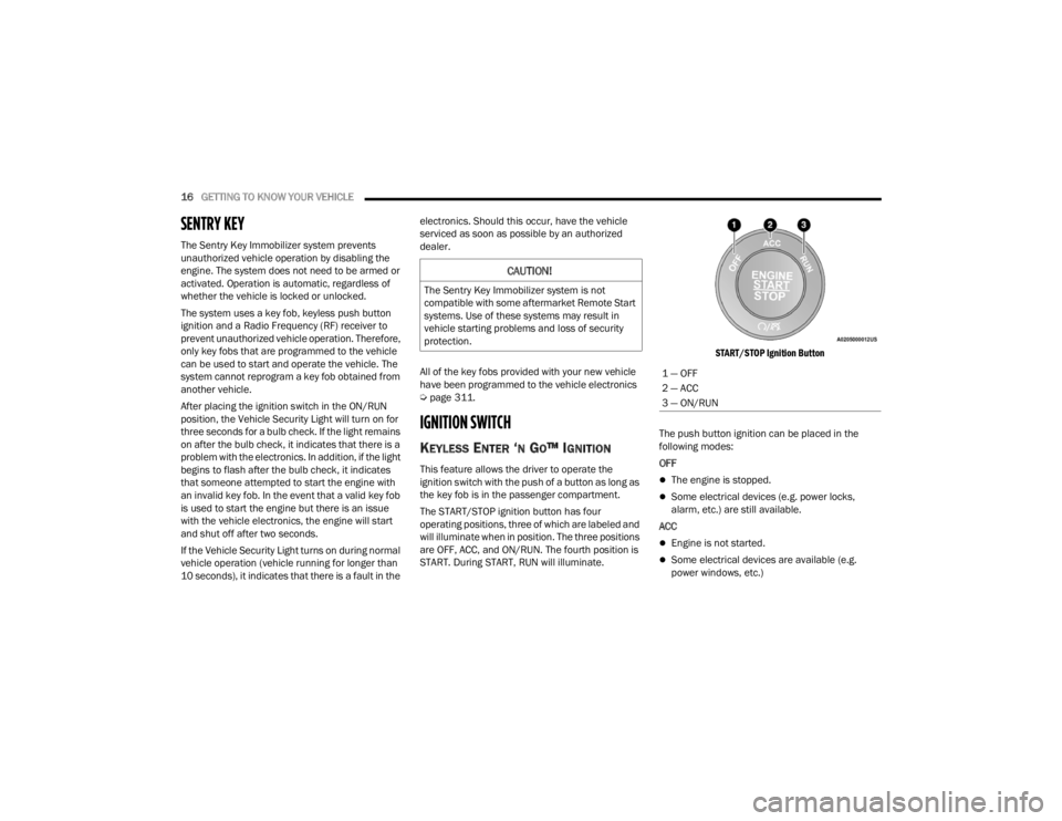
The START/STOP ignition button has four
operating positions, three of which are labeled and
will illuminate when in position. The three positions
are OFF, ACC, and ON/RUN. The fourth position is
START. During START, RUN will illuminate.
START/STOP Ignition Button
The push button ignition can be placed in the
following modes:
OFF The engine is stopped.
Some electrical devices (e.g. power locks,
alarm, etc.) are still available.
ACC
Engine is not started.
Some electrical devices are available (e.g.
power windows, etc.)
CAUTION!
The Sentry Key Immobilizer system is not
compatible with some aftermarket Remote Start
systems. Use of these systems may result in
vehicle starting problems and loss of security
protection.
1 — OFF
2 — ACC
3 — ON/RUN
21_LA_OM_EN_USC_t.book Page 16
Page 29 of 328
GETTING TO KNOW YOUR VEHICLE27
You can interrupt the help message or system
prompts by pushing the VR button and saying a
Voice Command from the current category.
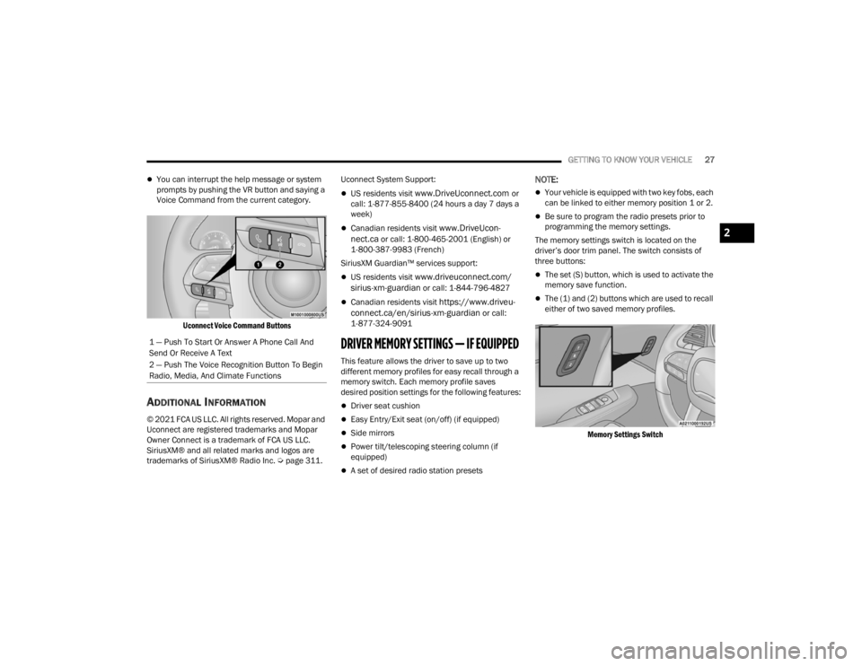
Uconnect Voice Command Buttons
ADDITIONAL INFORMATION
© 2021 FCA US LLC. All rights reserved. Mopar and
Uconnect are registered trademarks and Mopar
Owner Connect is a trademark of FCA US LLC.
SiriusXM® and all related marks and logos are
trademarks of SiriusXM® Radio Inc. Ú page 311.Uconnect System Support:
US residents visit www.DriveUconnect.com or
call: 1-877-855-8400 (24 hours a day 7 days a
week)
Canadian residents visit www.DriveUcon -
nect.ca or call: 1-800-465-2001 (English) or
1-800-387-9983 (French)
SiriusXM Guardian™ services support:
US residents visit www.driveuconnect.com/
sirius-xm-guardian or call: 1-844-796-4827
Canadian residents visit https://www.driveu -
connect.ca/en/sirius-xm-guardian or call:
1-877-324-9091
DRIVER MEMORY SETTINGS — IF EQUIPPED
This feature allows the driver to save up to two
different memory profiles for easy recall through a
memory switch. Each memory profile saves
desired position settings for the following features:
Driver seat cushion
Easy Entry/Exit seat (on/off) (if equipped)
Side mirrors
Power tilt/telescoping steering column (if
equipped)
A set of desired radio station presets
NOTE:
Your vehicle is equipped with two key fobs, each
can be linked to either memory position 1 or 2.
Be sure to program the radio presets prior to
programming the memory settings.
The memory settings switch is located on the
driver’s door trim panel. The switch consists of
three buttons:
The set (S) button, which is used to activate the
memory save function.
The (1) and (2) buttons which are used to recall
either of two saved memory profiles.
Memory Settings Switch
1 — Push To Start Or Answer A Phone Call And
Send Or Receive A Text
2 — Push The Voice Recognition Button To Begin
Radio, Media, And Climate Functions
2
21_LA_OM_EN_USC_t.book Page 27
Page 30 of 328
28GETTING TO KNOW YOUR VEHICLE
PROGRAMMING THE MEMORY FEATURE
To create a new memory profile, perform the
following:
NOTE:Saving a new memory profile will erase the
selected profile from memory.
1. Place the vehicle’s ignition in the ON/RUN
position (do not start the engine).
2. Adjust all memory profile settings to desired preferences (i.e., seat, side mirror, power tilt
and telescopic steering column [if equipped],
and radio station presets).
3. Push and release the set (S) button on the memory switch, and then push the desired
memory button (1 or 2) within five seconds.
The instrument cluster display will display
which memory position has been set.
NOTE:Memory profiles can be set without the vehicle in
PARK, but the vehicle must be in PARK to recall a
memory profile.
LINKING AND UNLINKING THE KEY FOB
T
O MEMORY
Your key fobs can be programmed to recall one of
two saved memory profiles.
NOTE:Before programming your key fobs you must select
the “Personal Settings Linked To Key Fob” feature
through the Uconnect system Ú page 120.
To program your key fobs, perform the following:
1. Place the vehicle’s ignition in the OFF position.
2. Select a desired memory profile, 1 or 2.
3. Once the profile has been recalled, push and release the set (S) button on the memory
switch.
4. Within five seconds, push and release button (1) or (2) accordingly. “Memory Profile Set” (1
or 2) will display in the instrument cluster.
5. Push and release the lock button on the key fob within 10 seconds.
NOTE:Your key fob can be unlinked from your memory
settings by pushing the set (S) button, followed by
pushing the unlock button on the key fob within 10
seconds.
MEMORY POSITION RECALL
NOTE:If a recall is attempted when the vehicle is not in
PARK, a message will be displayed in the
instrument cluster display.
To recall the memory settings for driver one or two,
push the desired memory button number (1 or 2)
or the unlock button on the key fob linked to the
desired memory position.
A recall can be canceled by pushing any of the
memory buttons (S, 1, or 2) during a recall. When
a recall is canceled, the driver seat will stop
moving. A delay of one second will occur before
another recall can be selected.
NOTE:If the vehicle is equipped with Passive Entry, the
memory settings are recalled when using Passive
Entry to unlock the driver's door with a linked key
fob.
21_LA_OM_EN_USC_t.book Page 28
Page 34 of 328
32GETTING TO KNOW YOUR VEHICLE
Easy Entry/Exit Seat — If Equipped
This feature provides automatic driver seat
positioning to enhance driver mobility when
entering and exiting the vehicle.
The distance the driver seat moves depends on
where you have the driver seat positioned when
you place the vehicle’s ignition in the OFF position.
When you place the vehicle’s ignition in the OFF
position, the driver seat will move about
2.4 inches (6.1 cm) rearward if the driver seat
position is greater than or equal to 2.7 inches
(6.8 cm) forward of the rear stop. The seat will
return to its previously set position when you
place the vehicle’s ignition in the ACC or RUN
position.
The Easy Entry/Easy Exit feature is disabled
when the driver seat position is less than 0.9 of
an inch (2.3 cm) forward of the rear stop. At this
position, there is no benefit to the driver by
moving the seat for Easy Exit or Easy Entry.
When enabled in Uconnect Settings, Easy Entry
and Easy Exit positions are stored in each memory
setting profile Ú page 27.
NOTE:The Easy Entry/Exit feature is enabled or disabled
through the programmable features in the
Uconnect system Ú page 120.
HEATED SEATS — IF EQUIPPED
On some models, the front seats may be equipped
with heaters located in the seat cushions and
seatbacks.
Front Heated Seats
The front heated seats control buttons are located
within the Uconnect system. You can gain access
to the control buttons through the climate screen
and the controls screen. You can choose from HI, LO, or OFF heat settings.
The indicator arrows in touchscreen buttons
indicate the level of heat in use. Two indicator
arrows will illuminate for HI, and one for LO.
Turning the heating elements off will return the
user to the radio screen.
Press the heated seat button once to turn
the HI setting on.
Press the heated seat button a second time
to turn the LO setting on.
Press the heated seat button a third time to
turn the heating elements off.
NOTE:
Once a heat setting is selected, heat will be felt
within two to five minutes.
The engine must be running for the heated
seats to operate.
If the HI-level setting is selected, the system will
automatically switch to LO-level after approxi-
mately 60 minutes of continuous operation. At
that time, the display will change from HI to LO,
indicating the change. The LO-level setting will
turn off automatically after approximately
45 minutes.
For information on use with the Remote Start
system, see Ú page 19.
WARNING!
Persons who are unable to feel pain to the
skin because of advanced age, chronic illness,
diabetes, spinal cord injury, medication,
alcohol use, exhaustion or other physical
condition must exercise care when using the
seat heater. It may cause burns even at low
temperatures, especially if used for long
periods of time.
Do not place anything on the seat or seatback
that insulates against heat, such as a blanket
or cushion. This may cause the seat heater to
overheat. Sitting in a seat that has been over -
heated could cause serious burns due to the
increased surface temperature of the seat.
21_LA_OM_EN_USC_t.book Page 32
Page 40 of 328
38GETTING TO KNOW YOUR VEHICLE
HEATED MIRRORS — IF EQUIPPED
These mirrors are heated to melt frost or
ice. This feature will be activated
whenever you turn on the rear window
defroster (if equipped) Úpage 48.
UNIVERSAL GARAGE DOOR OPENER
(HOMELINK®)
HomeLink® Buttons And Indicator Light
HomeLink® replaces up to three hand-held
transmitters that operate devices such as
garage door openers, motorized gates, lighting
or home security systems. The HomeLink® unit
is powered by your vehicle’s 12 Volt battery.
The HomeLink® buttons that are located in the
overhead console or sunvisor designate the
three different HomeLink® channels.
To operate HomeLink®, push and release any
of the programmed HomeLink® buttons. These
buttons will activate the devices they are
programmed to with each press of the corre -
sponding HomeLink® button.
The HomeLink® indicator light is located above
the center button Ú page 311.
BEFORE YOU BEGIN PROGRAMMING
H
OMELINK®
For efficient programming and accurate
transmission of the radio-frequency signal, it is
recommended that a new battery be placed in the
hand-held transmitter of the device that is being
programmed to the HomeLink® system. Make
sure your hand-held transmitter is programmed to
activate the device you are trying to program your
HomeLink® button to.
Ensure that your vehicle is parked outside of the
garage before you begin programming.
It is recommended that you erase all the channels
of your HomeLink® before you use it for the first
time. If you require assistance, please call toll-free
1-800-355-3515 or visit
HomeLink.com
ERASING ALL THE HOMELINK®
C
HANNELS
To erase the channels, follow this procedure:
1. Place the ignition switch into the ON/RUN
position.
2. Push and hold the two outside HomeLink® buttons (I and III) for up to 20 seconds, or until
the HomeLink® indicator light flashes.
NOTE:Erasing all channels should only be performed
when programming HomeLink® for the first time.
Do not erase channels when programming addi -
tional buttons.
IDENTIFYING WHETHER YOU HAVE A
R
OLLING CODE OR NON-ROLLING CODE
D
EVICE
Before programming a device to one of your
HomeLink® buttons, you must determine whether
the device has a rolling code or non-rolling code.
21_LA_OM_EN_USC_t.book Page 38
Page 42 of 328
40GETTING TO KNOW YOUR VEHICLE
PROGRAMMING HOMELINK® TO A
M
ISCELLANEOUS DEVICE
Follow the procedure on programming HomeLink®
to a garage door opener Ú page 39. Be sure to
determine if the device has a rolling code, or
non-rolling code before beginning the
programming process.
NOTE:Canadian radio frequency laws require transmitter
signals to time-out (or quit) after several seconds
of transmission, which may not be long enough for
HomeLink® to pick up the signal during
programming. Similar to this Canadian law, some
U.S. gate operators are designed to time-out in the
same manner. The procedure may need to be
performed multiple times to successfully pair the
device to your HomeLink® buttons.
REPROGRAMMING A SINGLE
H
OMELINK® BUTTON
To reprogram a single HomeLink® button that has
been previously trained, without erasing all the
channels, follow the procedure below. Be sure to
determine whether the new device you want to
program the HomeLink® button to has a rolling
code or non-rolling code.
1. Place the ignition in the ON/RUN position,
without starting the engine.
2. Push and hold the desired HomeLink® button until the HomeLink® Indicator light begins to
flash after 20 seconds. Do not release the
button.
3. Without releasing the button , proceed with
Step 2 in “Programming HomeLink® To A
Garage Door Opener” and follow all remaining
steps.
CANADIAN/GATE OPERATOR
P
ROGRAMMING
For programming transmitters in Canada/United
States that require the transmitter signals to
“time-out” after several seconds of transmission.
Canadian radio frequency laws require transmitter
signals to time-out (or quit) after several seconds
of transmission – which may not be long enough
for HomeLink® to pick up the signal during programming. Similar to this Canadian law, some
U.S. gate operators are designed to time-out in the
same manner.
It may be helpful to unplug the device during the
cycling process to prevent possible overheating of
the garage door or gate motor.
1. Place the ignition in the ON/RUN position.
2. Place the hand-held transmitter 1 to 3 inches
(3 to 8 cm) away from the HomeLink® button
you wish to program while keeping the
HomeLink® indicator light in view.
3. Continue to press and hold the HomeLink® button, while you press and release (cycle)
your hand-held transmitter every two seconds
until HomeLink® has successfully accepted
the frequency signal. The indicator light will
flash slowly and then rapidly when fully
trained.
4. Watch for the HomeLink® indicator to change flash rates. When it changes, it is
programmed. It may take up to 30 seconds or
longer in rare cases. The garage door may
open and close while you are programming.
5. Press and hold the programmed HomeLink® button and observe the indicator light.
Do not run your vehicle in a closed garage or
confined area while programming the trans -
ceiver. Exhaust gas from your vehicle contains
Carbon Monoxide (CO) which is odorless and
colorless. Carbon Monoxide is poisonous
when inhaled and can cause you and others to
be severely injured or killed.
WARNING!
21_LA_OM_EN_USC_t.book Page 40
Page 48 of 328
46GETTING TO KNOW YOUR VEHICLE
Instrument Panel Dimmer (Vehicles Sold In Canada Only)
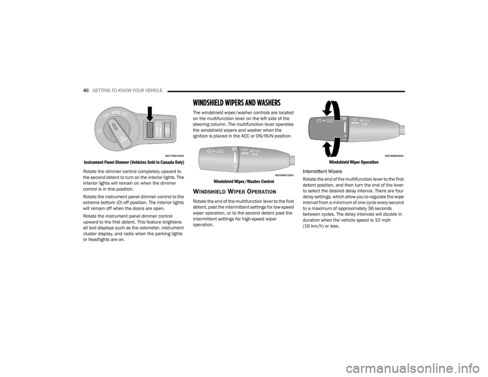
Rotate the dimmer control completely upward to
the second detent to turn on the interior lights. The
interior lights will remain on when the dimmer
control is in this position.
Rotate the instrument panel dimmer control to the
extreme bottom (O) off position. The interior lights
will remain off when the doors are open.
Rotate the instrument panel dimmer control
upward to the first detent. This feature brightens
all text displays such as the odometer, instrument
cluster display, and radio when the parking lights
or headlights are on.
WINDSHIELD WIPERS AND WASHERS
The windshield wiper/washer controls are located
on the multifunction lever on the left side of the
steering column. The multifunction lever operates
the windshield wipers and washer when the
ignition is placed in the ACC or ON/RUN position.
Windshield Wiper/Washer Control
WINDSHIELD WIPER OPERATION
Rotate the end of the multifunction lever to the first
detent, past the intermittent settings for low-speed
wiper operation, or to the second detent past the
intermittent settings for high-speed wiper
operation.
Windshield Wiper Operation
Intermittent Wipers
Rotate the end of the multifunction lever to the first
detent position, and then turn the end of the lever
to select the desired delay interval. There are four
delay settings, which allow you to regulate the wipe
interval from a minimum of one cycle every second
to a maximum of approximately 36 seconds
between cycles. The delay intervals will double in
duration when the vehicle speed is 10 mph
(16 km/h) or less.
21_LA_OM_EN_USC_t.book Page 46
Page 50 of 328
48GETTING TO KNOW YOUR VEHICLE
The Rain Sensing system has protection features
for the wiper blades and arms, and will not operate
under the following conditions:
Low Ambient Temperature — When the ignition
is first placed in the ON position, the Rain
Sensing system will not operate until the wiper
switch is moved, vehicle speed is greater than
0 mph (0 km/h), or the outside temperature is
greater than 32°F (0°C).
Transmission In NEUTRAL Position — When the
ignition is ON, and the transmission is in the
NEUTRAL position, the Rain Sensing system will
not operate until the wiper switch is moved,
vehicle speed is greater than 3 mph (5 km/h),
or the gear selector is moved out of the
NEUTRAL position.
Remote Start Mode Inhibit — On vehicles
equipped with Remote Start system, Rain
Sensing wipers are not operational when the
vehicle is in the Remote Start mode.
CLIMATE CONTROLS
The Climate Control system allows you to regulate
the temperature, air flow, and direction of air
circulating throughout the vehicle. The controls are
located on the touchscreen (if equipped) and on
the instrument panel below the radio.
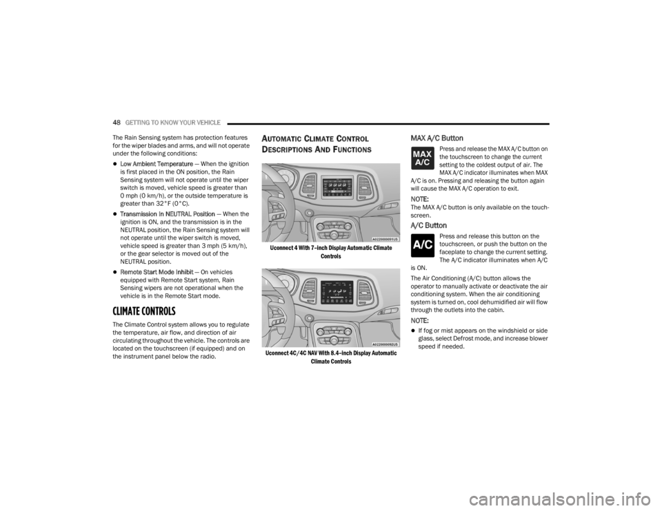
AUTOMATIC CLIMATE CONTROL
D
ESCRIPTIONS AND FUNCTIONS
Uconnect 4 With 7–inch Display Automatic Climate
Controls
Uconnect 4C/4C NAV With 8.4–inch Display Automatic Climate Controls
MAX A/C Button
Press and release the MAX A/C button on
the touchscreen to change the current
setting to the coldest output of air. The
MAX A/C indicator illuminates when MAX
A/C is on. Pressing and releasing the button again
will cause the MAX A/C operation to exit.
NOTE:The MAX A/C button is only available on the touch -
screen.
A/C Button
Press and release this button on the
touchscreen, or push the button on the
faceplate to change the current setting.
The A/C indicator illuminates when A/C
is ON.
The Air Conditioning (A/C) button allows the
operator to manually activate or deactivate the air
conditioning system. When the air conditioning
system is turned on, cool dehumidified air will flow
through the outlets into the cabin.
NOTE:
If fog or mist appears on the windshield or side
glass, select Defrost mode, and increase blower
speed if needed.
21_LA_OM_EN_USC_t.book Page 48