check engine DODGE CHALLENGER 2023 Owner's Manual
[x] Cancel search | Manufacturer: DODGE, Model Year: 2023, Model line: CHALLENGER, Model: DODGE CHALLENGER 2023Pages: 300, PDF Size: 12.82 MB
Page 158 of 300
156MULTIMEDIA
NOTE:
Launch Control should not be used on public roads.
Always check track conditions and the surrounding
area.
Launch Control is not available for the first 500 miles
(805 km) of the vehicle’s life.
Launch Control should only be used when the engine
and transmission are at operating temperature.
Launch Control is intended to be used on dry, paved
road surfaces only. Use on slippery or loose surfaces
may cause damage to vehicle components and is not
recommended.
Launch Control is not available in ESC Full Off Mode.
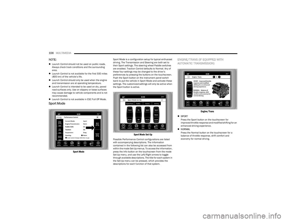
Sport Mode
Sport Mode
Sport Mode is a configuration setup for typical enthusiast
driving. The Transmission and Steering are both set to
their Sport settings. The steering wheel Paddle switches
are enabled. Traction Control defaults to Normal. Any of
these four settings may be changed to the driver’s
preferences by pressing the buttons on the touchscreen.
Push the Sport button on the instrument panel switch
bank to put the vehicle in Sport Mode and activate these
settings. The customized settings will only be active when
the Sport button is active.
Sport Mode Set-Up
Possible Performance Control configurations are listed
with accompanying descriptions. The information
contained in the following list can also be accessed from
within the mode Set-Up menus. To access the information,
press the Info button on the touchscreen from the mode
Set-Up menu, and use the Left/Right arrows to toggle
through available descriptions. The title for each system in
the Set-Up menu can be pressed, which provides the
descriptions for each function of that system.
ENGINE/TRANS (IF EQUIPPED WITH
AUTOMATIC TRANSMISSION)
Engine/Trans
SPORT
Press the Sport button on the touchscreen for
improved throttle response and modified shifting for an
enhanced driving experience.
NORMAL
Press the Normal button on the touchscreen for a
balance of throttle response, shift comfort and
economy for normal driving.
23_LA_OM_EN_USC_t.book Page 156
Page 181 of 300
SAFETY179
NOTE:Vehicles with the front passenger seat deleted will not be
equipped with the Seat Belt Buckle Switch, Seat Belt
Pretensioner, Supplemental Seat Mounted Side Airbag,
and Seat Track Position Sensors for the front passenger.
All passenger occupants within the vehicle must be in a
seat equipped with a Seat Belt System and Head Restraint
for the safety of the passenger.
If the front passenger and/or rear seats have been
removed do not ride in those areas.
Air Bag Warning Light
The Occupant Restraint Controller (ORC)
monitors the readiness of the electronic parts
of the air bag system whenever the ignition
switch is in the START or ON/RUN position. If
the ignition switch is in the OFF position or in the ACC
position, the air bag system is not on and the air bags will
not inflate.
The ORC contains a backup power supply system that may
deploy the air bag system even if the battery loses power
or it becomes disconnected prior to deployment. The ORC turns on the Air Bag Warning Light in the
instrument panel for approximately four to eight seconds
for a self-check when the ignition switch is first in the ON/
RUN position. After the self-check, the Air Bag Warning
Light will turn off. If the ORC detects a malfunction in any
part of the system, it turns on the Air Bag Warning Light,
either momentarily or continuously. A single chime will
sound to alert you if the light comes on again after initial
startup.
The ORC also includes diagnostics that will illuminate the
instrument panel Air Bag Warning Light if a malfunction is
detected that could affect the air bag system. The
diagnostics also record the nature of the malfunction.
While the air bag system is designed to be maintenance
free, if any of the following occurs, have an authorized
dealer service the air bag system immediately.
The Air Bag Warning Light does not come on during the
four to eight seconds when the ignition switch is first in
the ON/RUN position.
The Air Bag Warning Light remains on after the four to
eight-second interval.
The Air Bag Warning Light comes on intermittently or
remains on while driving.
NOTE:If the speedometer, tachometer, or any engine related
gauges are not working, the Occupant Restraint Controller
(ORC) may also be disabled. In this condition the air bags
may not be ready to inflate for your protection. Have an
authorized dealer service the air bag system immediately.
Redundant Air Bag Warning Light
If a fault with the Air Bag Warning Light is
detected, which could affect the Supplemental
Restraint System (SRS), the Redundant Air Bag
Warning Light will illuminate on the instrument
panel. The Redundant Air Bag Warning Light will stay on
until the fault is cleared. In addition, a single chime will
sound to alert you that the Redundant Air Bag Warning
Light has come on and a fault has been detected. If the
Redundant Air Bag Warning Light comes on intermittently
or remains on while driving have an authorized dealer
service the vehicle immediately
Úpage 63.
WARNING!
Ignoring the Air Bag Warning Light in your instrument
panel could mean you won’t have the air bag system to
protect you in a collision. If the light does not come on
as a bulb check when the ignition is first turned on,
stays on after you start the vehicle, or if it comes on as
you drive, have an authorized dealer service the air bag
system immediately.
6
23_LA_OM_EN_USC_t.book Page 179
Page 186 of 300
184SAFETY
(Continued)
Do not drive your vehicle after the air bags have deployed.
If you are involved in another collision, the air bags will not
be in place to protect you.
NOTE:
Air bag covers may not be obvious in the interior trim,
but they will open during air bag deployment.
After any collision, the vehicle should be taken to an
authorized dealer immediately.
Enhanced Accident Response System
In the event of an impact, if the communication network
remains intact, and the power remains intact, depending
on the nature of the event, the Occupant Restraint
Controller (ORC) will determine whether to have the
Enhanced Accident Response System perform the
following functions:
Cut off fuel to the engine (if equipped).
Cut off battery power to the electric motor (if equipped).
Flash hazard lights as long as the battery has power.
Turn on the interior lights, which remain on as long as
the battery has power or for 15 minutes from the inter -
vention of the Enhanced Accident Response System.
Unlock the power door locks. Your vehicle may also be designed to perform any of these
other functions in response to the Enhanced Accident
Response System:
Turn off the Fuel Filter Heater, Turn off the HVAC Blower
Motor, Close the HVAC Circulation Door
Cut off battery power to the:
Engine
Electric Motor (if equipped)
Electric power steering
Brake booster
Electric park brake
Automatic transmission gear selector
Horn
Front wiper
NOTE:After an accident, remember to cycle the ignition to the
STOP (OFF/LOCK) position and remove the key from the
ignition switch to avoid draining the battery. Carefully
check the vehicle for fuel leaks in the engine compartment
and on the ground near the engine compartment and fuel
tank before resetting the system and starting the engine.
If there are no fuel leaks or damage to the vehicle elec -
trical devices (e.g. headlights) after an accident, reset the
system by following the procedure described below. If you
have any doubt, contact an authorized dealer.
Enhanced Accident Response System
Reset Procedure
In order to reset the Enhanced Accident Response System
functions after an event, the ignition switch must be
changed from ignition START or ON/RUN to ignition OFF.
Carefully check the vehicle for fuel leaks in the engine
compartment and on the ground near the engine
compartment and fuel tank before resetting the system
and starting the engine.
After an accident, if the vehicle will not start after
performing the reset procedure, the vehicle must be
towed to an authorized dealer to be inspected and to have
the Enhanced Accident Response System reset.
Maintaining Your Air Bag System
WARNING!
Deployed air bags and seat belt pretensioners cannot
protect you in another collision. Have the air bags, seat
belt pretensioners, and the seat belt retractor
assemblies replaced by an authorized dealer
immediately. Also, have the Occupant Restraint
Controller System serviced as well.
WARNING!
Modifications to any part of the air bag system could
cause it to fail when you need it. You could be injured
if the air bag system is not there to protect you. Do
not modify the components or wiring, including
adding any kind of badges or stickers to the steering
wheel hub trim cover or the upper passenger side of
the instrument panel. Do not modify the front fascia/
bumper, vehicle body structure, or add aftermarket
side steps or running boards.
It is dangerous to try to repair any part of the air bag
system yourself. Be sure to tell anyone who works on
your vehicle that it has an air bag system.
23_LA_OM_EN_USC_t.book Page 184
Page 199 of 300
SAFETY197
(Continued)
(Continued)
After the bulb check, this light will illuminate with a single
chime when a fault with the Air Bag System has been
detected. It will stay on until the fault is removed. If the
light comes on intermittently or remains on while driving,
have an authorized dealer service the vehicle immediately
Úpage 172.
Defroster
Check operation by selecting the defrost mode and place
the blower control on high speed. You should be able to
feel the air directed against the windshield. See an
authorized dealer for service if your defroster is
inoperable.
Floor Mat Safety Information
Always use floor mats designed to fit your vehicle. Only use
a floor mat that does not interfere with the operation of the
accelerator, brake or clutch pedals. Only use a floor mat
that is securely attached using the floor mat fasteners so
it cannot slip out of position and interfere with the
accelerator, brake or clutch pedals or impair safe
operation of your vehicle in other ways.
WARNING!
An improperly attached, damaged, folded, or stacked
floor mat, or damaged floor mat fasteners may cause
your floor mat to interfere with the accelerator, brake, or
clutch pedals and cause a loss of vehicle control. To
prevent SERIOUS INJURY or DEATH:
ALWAYS securely attach your floor mat
using the floor mat fasteners. DO NOT
install your floor mat upside down or turn
your floor mat over. Lightly pull to confirm
mat is secured using the floor mat fasteners on a
regular basis.
ALWAYS REMOVE THE EXISTING FLOOR
MAT FROM THE VEHICLE before installing
any other floor mat. NEVER install or stack
an additional floor mat on top of an
existing floor mat.
ONLY install floor mats designed to fit your vehicle.
NEVER install a floor mat that cannot be properly
attached and secured to your vehicle. If a floor mat
needs to be replaced, only use a FCA approved floor
mat for the specific make, model, and year of your
vehicle.
ONLY use the driver’s side floor mat on the driver’s
side floor area. To check for interference, with the
vehicle properly parked with the engine off, fully
depress the accelerator, the brake, and the clutch
pedal (if present) to check for interference. If your
floor mat interferes with the operation of any pedal,
or is not secure to the floor, remove the floor mat
from the vehicle and place the floor mat in your
trunk.
ONLY use the passenger’s side floor mat on the
passenger’s side floor area.
WARNING!
ALWAYS make sure objects cannot fall or slide into
the driver’s side floor area when the vehicle is
moving. Objects can become trapped under acceler -
ator, brake, or clutch pedals and could cause a loss
of vehicle control.
NEVER place any objects under the floor mat
(e.g., towels, keys, etc.). These objects could change
the position of the floor mat and may cause interfer-
ence with the accelerator, brake, or clutch pedals.
If the vehicle carpet has been removed and
re-installed, always properly attach carpet to the floor
and check the floor mat fasteners are secure to the
vehicle carpet. Fully depress each pedal to check for
interference with the accelerator, brake, or clutch
pedals then re-install the floor mats.
It is recommended to only use mild soap and water
to clean your floor mats. After cleaning, always check
your floor mat has been properly installed and is
secured to your vehicle using the floor mat fasteners
by lightly pulling mat.
WARNING!
6
23_LA_OM_EN_USC_t.book Page 197
Page 200 of 300

198SAFETY
PERIODIC SAFETY CHECKS YOU SHOULD
M
AKE OUTSIDE THE VEHICLE
Tires
Examine tires for excessive tread wear and uneven wear
patterns. Check for stones, nails, glass, or other objects
lodged in the tread or sidewall. Inspect the tread for cuts
and cracks. Inspect sidewalls for cuts, cracks, and bulges.
Check the lug nuts/bolt torque for tightness. Check the
tires (including spare) for proper cold inflation pressure.
Lights
Have someone observe the operation of brake lights and
exterior lights while you work the controls. Check turn
signal and high beam indicator lights on the instrument
panel.
Door Latches
Check for proper closing, latching, and locking.
Fluid Leaks
Check area under the vehicle after overnight parking for
fuel, coolant, oil, or other fluid leaks. Also, if gasoline
fumes are detected or if fuel or brake fluid leaks are
suspected, the cause should be located and corrected
immediately.
EXHAUST GAS
The best protection against carbon monoxide entry into
the vehicle body is a properly maintained engine exhaust
system. Whenever a change is noticed in the sound of the exhaust
system, when exhaust fumes can be detected inside the
vehicle, or when the underside or rear of the vehicle is
damaged, have an authorized dealer inspect the complete
exhaust system and adjacent body areas for broken,
damaged, deteriorated, or mispositioned parts. Open
seams or loose connections could permit exhaust fumes
to seep into the passenger compartment. In addition,
inspect the exhaust system each time the vehicle is raised
for lubrication or oil change. Replace as required.
CARBON MONOXIDE WARNINGS
WARNING!
Exhaust gases can injure or kill. They contain carbon
monoxide (CO), which is colorless and odorless.
Breathing it can make you unconscious and can
eventually poison you. To avoid breathing (CO), follow
these safety tips:
Do not run the engine in a closed garage or in
confined areas any longer than needed to move your
vehicle in or out of the area.
If you are required to drive with the trunk/liftgate/
rear doors open, make sure that all windows are
closed and the climate control BLOWER switch is set
at high speed. DO NOT use the recirculation mode.
If it is necessary to sit in a parked vehicle with the
engine running, adjust your heating or cooling
controls to force outside air into the vehicle. Set the
blower at high speed.
WARNING!
Carbon monoxide (CO) in exhaust gases is deadly.
Follow the precautions below to prevent carbon
monoxide poisoning:
Do not inhale exhaust gases. They contain carbon
monoxide, a colorless and odorless gas, which can
kill. Never run the engine in a closed area, such as a
garage, and never sit in a parked vehicle with the
engine running for an extended period. If the vehicle
is stopped in an open area with the engine running
for more than a short period, adjust the ventilation
system to force fresh, outside air into the vehicle.
Guard against carbon monoxide with proper mainte -
nance. Have the exhaust system inspected every
time the vehicle is raised. Have any abnormal condi -
tions repaired promptly. Until repaired, drive with all
side windows fully open.
23_LA_OM_EN_USC_t.book Page 198
Page 210 of 300
208IN CASE OF EMERGENCY
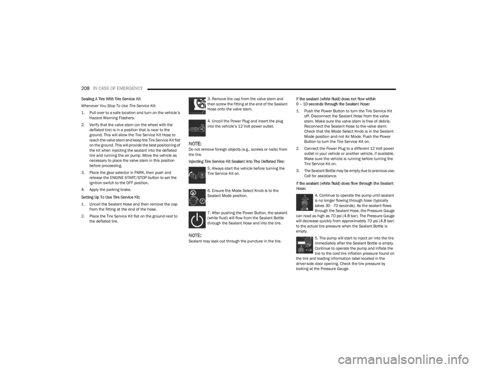
Sealing A Tire With Tire Service Kit
Whenever You Stop To Use Tire Service Kit:
1. Pull over to a safe location and turn on the vehicle’s
Hazard Warning Flashers.
2. Verify that the valve stem (on the wheel with the deflated tire) is in a position that is near to the
ground. This will allow the Tire Service Kit Hose to
reach the valve stem and keep the Tire Service Kit flat
on the ground. This will provide the best positioning of
the kit when injecting the sealant into the deflated
tire and running the air pump. Move the vehicle as
necessary to place the valve stem in this position
before proceeding.
3. Place the gear selector in PARK, then push and release the ENGINE START/STOP button to set the
ignition switch to the OFF position.
4. Apply the parking brake.
Setting Up To Use Tire Service Kit:
1. Uncoil the Sealant Hose and then remove the cap from the fitting at the end of the hose.
2. Place the Tire Service Kit flat on the ground next to the deflated tire. 3. Remove the cap from the valve stem and
then screw the fitting at the end of the Sealant
Hose onto the valve stem.
4. Uncoil the Power Plug and insert the plug
into the vehicle’s 12 Volt power outlet.
NOTE:Do not remove foreign objects (e.g., screws or nails) from
the tire.
Injecting Tire Service Kit Sealant Into The Deflated Tire:
5. Always start the vehicle before turning the
Tire Service Kit on.
6. Ensure the Mode Select Knob is to the
Sealant Mode position.
7. After pushing the Power Button, the sealant
(white fluid) will flow from the Sealant Bottle
through the Sealant Hose and into the tire.
NOTE:Sealant may leak out through the puncture in the tire. If the sealant (white fluid) does not flow within
0 – 10 seconds through the Sealant Hose:
1. Push the Power Button to turn the Tire Service Kit
off. Disconnect the Sealant Hose from the valve
stem. Make sure the valve stem is free of debris.
Reconnect the Sealant Hose to the valve stem.
Check that the Mode Select Knob is in the Sealant
Mode position and not Air Mode. Push the Power
Button to turn the Tire Service Kit on.
2. Connect the Power Plug to a different 12 Volt power outlet in your vehicle or another vehicle, if available.
Make sure the vehicle is running before turning the
Tire Service Kit on.
3. The Sealant Bottle may be empty due to previous use. Call for assistance.
If the sealant (white fluid) does flow through the Sealant
Hose: 4. Continue to operate the pump until sealant
is no longer flowing through hose (typically
takes 30 - 70 seconds). As the sealant flows
through the Sealant Hose, the Pressure Gauge
can read as high as 70 psi (4.8 bar). The Pressure Gauge
will decrease quickly from approximately 70 psi (4.8 bar)
to the actual tire pressure when the Sealant Bottle is
empty.
5. The pump will start to inject air into the tire
immediately after the Sealant Bottle is empty.
Continue to operate the pump and inflate the
tire to the cold tire inflation pressure found on
the tire and loading information label located in the
driver-side door opening. Check the tire pressure by
looking at the Pressure Gauge.
23_LA_OM_EN_USC_t.book Page 208
Page 216 of 300
214IN CASE OF EMERGENCY
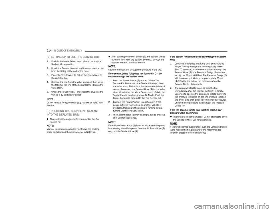
(B) SETTING UP TO USE TIRE SERVICE KIT:
1. Push in the Mode Select Knob (6) and turn to the
Sealant Mode position.
2. Uncoil the Sealant Hose (4) and then remove the cap from the fitting at the end of the hose.
3. Place the Tire Service Kit flat on the ground next to the deflated tire.
4. Remove the cap from the valve stem and then screw the fitting at the end of the Sealant Hose (4) onto the
valve stem.
5. Uncoil the Power Plug (7) and insert the plug into the vehicle’s 12 Volt power outlet.
NOTE:Do not remove foreign objects (e.g., screws or nails) from
the tire.
(C) INJECTING TIRE SERVICE KIT SEALANT
INTO THE DEFLATED TIRE:
Always start the engine before turning ON the Tire
Service Kit.
NOTE:Manual transmission vehicles must have the parking
brake engaged and the gear selector in NEUTRAL.
After pushing the Power Button (3), the sealant (white
fluid) will flow from the Sealant Bottle (1) through the
Sealant Hose (4) and into the tire.
NOTE:Sealant may leak out through the puncture in the tire.
If the sealant (white fluid) does not flow within 0 – 10
seconds through the Sealant Hose :
1. Push the Power Button (3) to turn Off the Tire
Service Kit. Disconnect the Sealant Hose (4) from
the valve stem. Make sure the valve stem is free of
debris. Reconnect the Sealant Hose (4) to the valve
stem. Check that the Mode Select Knob (6) is in the
Sealant Mode position and not Air Mode. Push the
Power Button (3) to turn On the Tire Service Kit.
2. Connect the Power Plug (7) to a different 12 Volt power outlet in your vehicle or another vehicle, if
available. Make sure the engine is running before
turning ON the Tire Service Kit.
3. The Sealant Bottle (1) may be empty due to previous use. Call for assistance.
NOTE:If the Mode Select Knob (6) is on Air Mode and the pump
is operating, air will dispense from the Air Pump Hose (8)
only, not the Sealant Hose (4). If the sealant (white fluid) does flow through the Sealant
Hose :
1. Continue to operate the pump until sealant is no
longer flowing through the hose (typically takes
30 - 70 seconds). As the sealant flows through the
Sealant Hose (4), the Pressure Gauge (5) can read
as high as 70 psi (4.8 Bar). The Pressure Gauge (5)
will decrease quickly from approximately 70 psi
(4.8 Bar) to the actual tire pressure when the
Sealant Bottle (1) is empty.
2. The pump will start to inject air into the tire immediately after the Sealant Bottle (1) is empty.
Continue to operate the pump and inflate the tire to
the pressure indicated on the tire pressure label on
the driver-side latch pillar (recommended pressure).
Check the tire pressure by looking at the Pressure
Gauge (5).
If the tire does not inflate to at least 26 psi (1.8 Bar)
pressure within 15 minutes:
The tire is too badly damaged. Do not attempt to drive
the vehicle further. Call for assistance.NOTE:If the tire becomes overinflated, push the Deflation Button
(2) to reduce the tire pressure to the recommended
inflation pressure before continuing.
23_LA_OM_EN_USC_t.book Page 214
Page 225 of 300
223
SERVICING AND MAINTENANCE
SCHEDULED SERVICING
3.6L AND 5.7L ENGINES
These engines are equipped with an automatic oil change
indicator system. The oil change indicator system will
remind you that it is time to take your vehicle in for
scheduled maintenance.Based on engine operation conditions, the oil change
indicator message will illuminate. This means that service
is required for the vehicle. Operating conditions such as
frequent short-trips, trailer tow, and extremely hot or cold
ambient temperatures will influence when the “Change
Oil” or “Oil Change Required” message is displayed. Have
your vehicle serviced as soon as possible, within the next
500 miles (805 km).
The “Oil Change Required” message will be displayed in
the instrument cluster and a single chime will sound,
indicating that an oil change is necessary.
An authorized dealer will reset the oil change indicator
message after completing the scheduled oil change.
NOTE:Under no circumstances should oil change intervals
exceed 10,000 miles (16,000 km), 12 months or
350 hours of engine run time, whichever comes first.
The 350 hours of engine run or idle time is generally only
a concern for fleet customers.Once A Month Or Before A Long Trip:
Check engine oil level.
Check windshield washer fluid level.
Check tire pressure and look for unusual wear or
damage. Rotate tires at the first sign of irregular wear,
even if it occurs before your next scheduled service.
Check the fluid levels of the coolant reservoir, brake
master cylinder, and power steering (if equipped) and
fill as needed.
Check function of all interior and exterior lights.
8
23_LA_OM_EN_USC_t.book Page 223
Page 232 of 300
230SERVICING AND MAINTENANCE
CHECKING OIL LEVELTo ensure proper engine lubrication, the engine oil must
be maintained at the correct level. Check the oil level at
regular intervals, such as every fuel stop. The best time to
check the engine oil level is about ten minutes after a fully
warmed up engine is shut off.
Checking the oil while the vehicle is on level ground will
improve the accuracy of the oil level readings.
There are four possible dipstick types:
Crosshatched zone.
Crosshatched zone marked SAFE.
Crosshatched zone marked with MIN at the low end of
the range and MAX at the high end of the range.
Crosshatched zone marked with dimples at the MIN
and the MAX ends of the range.
NOTE:Always maintain the oil level within the crosshatch
markings on the dipstick.
Adding 1 qt (1 L) of oil when the reading is at the low end
of the dipstick range will raise the oil level to the high end
of the range marking.
ADDING WASHER FLUID
The windshield washer fluid reservoir is located in the
front of the engine compartment. Be sure to check the
fluid level at regular intervals. Fill the reservoir with
windshield washer solvent (not radiator antifreeze) and
operate the system for a few seconds to flush out the
residual water.
When refilling the washer fluid reservoir, apply some
washer fluid to a cloth or towel and wipe the wiper blades
clean. This will help blade performance.
To prevent freeze-up of your windshield washer system in
cold weather, select a solution or mixture that meets or
exceeds the temperature range of your climate. This rating
information can be found on most washer fluid containers.
The fluid reservoir will hold nearly 1 Gallon (4 Liters) of
washer fluid when the message “Low Washer Fluid”
appears in the instrument cluster.WARNING!
Never smoke while working in the engine compart -
ment: gas and flammable vapors may be present,
with the risk of fire.
Be very careful when working in the engine compart -
ment when the engine is hot: you may get burned. Do
not get too close to the radiator cooling fan: the elec -
tric fan may start; danger of injury. Scarves, ties and
other loose clothing might be pulled by moving parts.
CAUTION!
Be careful not to confuse the various types of fluids
while topping up: they are not compatible with each
other! Topping up with an unsuitable fluid could
severely damage your car.
The oil level must never exceed the MAX mark.
Always top up using engine oil of the same specifica -
tions as what is already in the engine.
If the engine oil is being topped up, wait for the
engine to cool down before loosening the filler cap,
particularly for vehicles with aluminum caps (if
equipped). WARNING: risk of burns!
Overfilling or underfilling the crankcase will cause
aeration or loss of oil pressure. This could damage
your engine.
CAUTION!
Overfilling or underfilling the crankcase will cause
aeration or loss of oil pressure. This could damage your
engine.
WARNING!
Commercially available windshield washer solvents are
flammable. They could ignite and burn you. Care must
be exercised when filling or working around the washer
solution.
23_LA_OM_EN_USC_t.book Page 230
Page 240 of 300
238SERVICING AND MAINTENANCE
Coolant Checks
Check engine coolant (antifreeze) protection every
12 months (before the onset of freezing weather, where
applicable). If the engine coolant is dirty, the system
should be drained, flushed, and refilled with fresh Organic
Additive Technology (OAT) coolant (conforming to
MS.90032) by an authorized dealer. Check the front of the
radiator for any accumulation of bugs, leaves, etc. If dirty,
clean by gently spraying water from a garden hose
vertically down the face of the condenser.
Check the coolant recovery bottle tubing for brittle rubber,
cracking, tears, cuts, and tightness of the connection at
the bottle and radiator. Inspect the entire system for
leaks. DO NOT REMOVE THE COOLANT PRESSURE CAP
WHEN THE COOLING SYSTEM IS HOT.
Cooling System — Drain, Flush And Refill
NOTE:Some vehicles require special tools to add coolant
properly. Failure to fill these systems properly could lead
to severe internal engine damage. If any coolant is needed
to be added to the system please contact an authorized
dealer.
If the engine coolant (antifreeze) is dirty or contains visible
sediment, have an authorized dealer clean and flush with
Organic Additive Technology (OAT) coolant (conforming to
MS.90032).
For the proper maintenance intervals
Úpage 224.
Selection Of Coolant
For further information Úpage 278.
NOTE:
Mixing of engine coolant (antifreeze) other than speci-
fied Organic Additive Technology (OAT) engine coolant,
may result in engine damage and may decrease corro -
sion protection. OAT engine coolant is different and
should not be mixed with Hybrid Organic Additive Tech -
nology (HOAT) engine coolant or any “globally compat -
ible” coolant. If a non-OAT engine coolant is introduced
into the cooling system in an emergency, the cooling
system will need to be drained, flushed, and refilled
with fresh OAT coolant (conforming to MS.90032), by
an authorized dealer as soon as possible.
Do not use water alone or alcohol-based engine
coolant products. Do not use additional rust inhibitors
or antirust products, as they may not be compatible
with the radiator engine coolant and may plug the radi -
ator.
This vehicle has not been designed for use with
propylene glycol-based engine coolant. Use of
propylene glycol-based engine coolant is not recom -
mended.
Some vehicles require special tools to add coolant
properly. Failure to fill these systems properly could
lead to severe internal engine damage. If any coolant is
needed to be added to the system please contact an
authorized dealer.
Adding Coolant
Your vehicle has been built with an improved engine
coolant (OAT coolant conforming to MS.90032) that
allows extended maintenance intervals. This engine
coolant (antifreeze) can be used up to 10 years or
150,000 miles (240,000 km) before replacement. To
prevent reducing this extended maintenance period, it is
important to use the same engine coolant (OAT coolant
conforming to MS.90032) throughout the life of your
vehicle.
Please review these recommendations for using Organic
Additive Technology (OAT) engine coolant that meets the
requirements of the manufacturer Material Standard
MS.90032. When adding engine coolant:
We recommend using Mopar® Antifreeze/Coolant
10 Year/150,000 Mile (240,000 km) Formula OAT
that meets the requirements of the manufacturer
Material Standard MS.90032.
Mix a minimum solution of 50% OAT engine coolant
that meets the requirements of the manufacturer
Material Standard MS.90032 and distilled water.
Use higher concentrations (not to exceed 70%) if
temperatures below −34°F (−37°C) are anticipated.
Please contact an authorized dealer for assistance.
Use only high purity water such as distilled or deionized
water when mixing the water/engine coolant solution.
The use of lower quality water will reduce the amount
of corrosion protection in the engine cooling system.
23_LA_OM_EN_USC_t.book Page 238