horn DODGE CHARGER 2011 7.G Owners Manual
[x] Cancel search | Manufacturer: DODGE, Model Year: 2011, Model line: CHARGER, Model: DODGE CHARGER 2011 7.GPages: 104, PDF Size: 4.53 MB
Page 12 of 104

NOTE:
• If “Unlock All Doors 1st Press” is programmed all doors will unlock when you grabhold of the front driver's door handle. To select between “Unlock Driver Door 1st
Press” and “Unlock All Doors 1st Press”, refer to the Uconnect Touch™ Settings in
your vehicle's Owner's Manual on the DVD or Programmable Features in this guide for
further information.
• To select between “Unlock Driver Door 1st Press” and “Unlock All Doors 1st Press”, refer to the Uconnect Touch™ Settings in your vehicle's Owner's Manual on the DVD
or Programmable Features in this guide for further information.
• If a Key Fob is detected in the vehicle when locking the vehicle using the power door lock switch, the doors will unlock and the horn will chirp three times. On the third
attempt, your Key Fob can be locked inside the vehicle.
• After pressing the Keyless Enter-N-Go LOCK button, you must wait 2 seconds before you can lock or unlock the vehicle using the door handle.
• If a Keyless Enter-N-Go door handle has not been used for 72 hours, the Keyless Enter-N-Go feature for that handle may time out. Pulling the deactivated front door
handle will reactivate the door handle's Keyless Enter-N-Go feature.
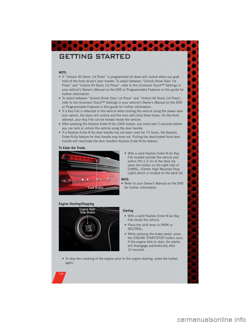
To Enter the Trunk:
• With a valid Keyless Enter-N-Go KeyFob located outside the vehicle and
within 5ft (1.5 m) of the deck lid,
press the button on the right side of
CHMSL, (Center High Mounted Stop
Light) which is located on the deck lid.
NOTE:
• Refer to your Owner's Manual on the DVD for further information.
Engine Starting/Stopping
Starting
• With a valid Keyless Enter-N-Go Key Fob inside the vehicle.
• Place the shift lever in PARK or NEUTRAL.
• While pressing the brake pedal, press the ENGINE START/STOP button once.
If the engine fails to start, the starter
will disengage automatically after
10 seconds.
• To stop the cranking of the engine prior to the engine starting, press the button again.
GETTING STARTED
10
Page 88 of 104

FUSES
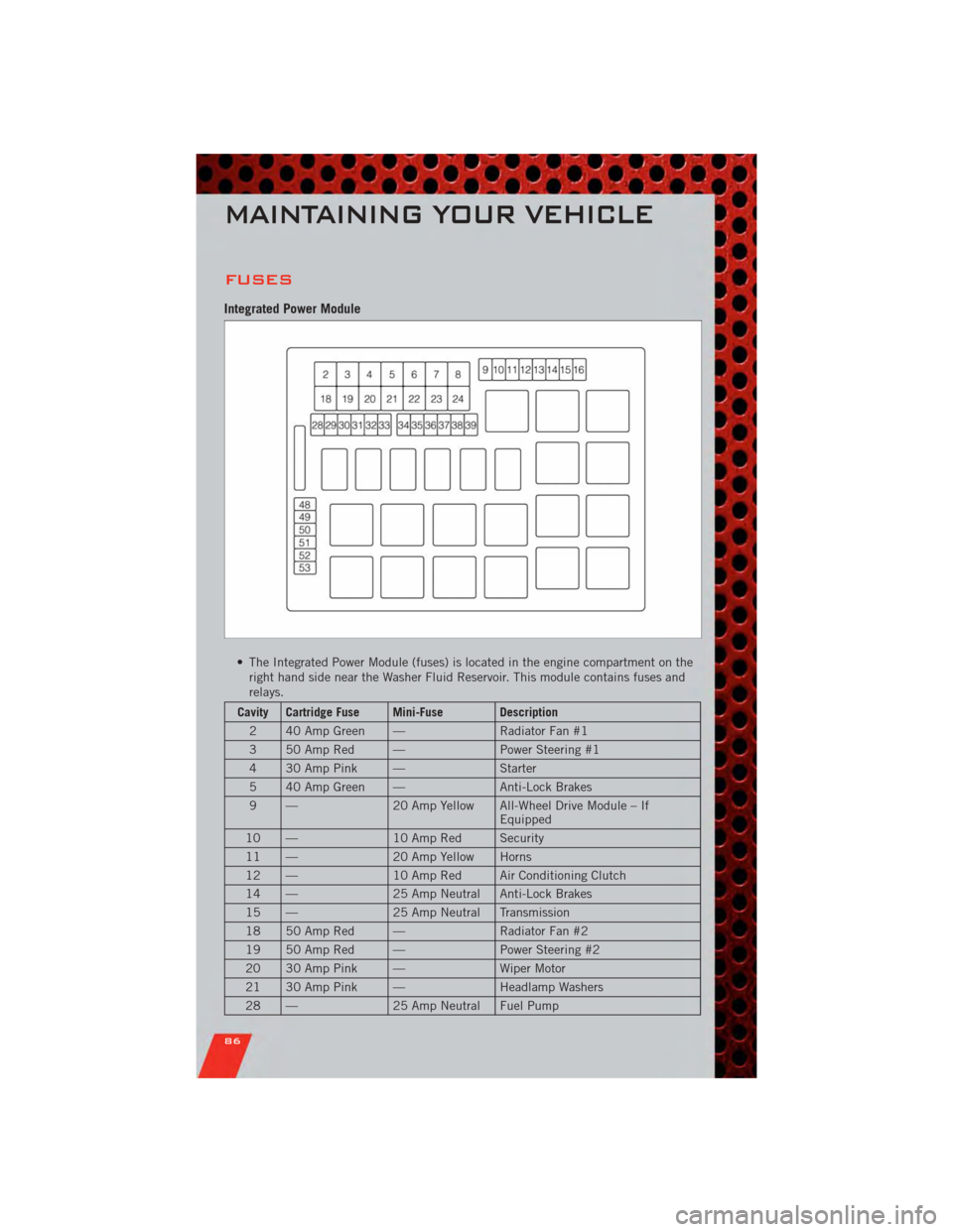
Integrated Power Module
• The Integrated Power Module (fuses) is located in the engine compartment on theright hand side near the Washer Fluid Reservoir. This module contains fuses and
relays.
Cavity Cartridge Fuse Mini-Fuse Description
2 40 Amp Green — Radiator Fan #1
3 50 Amp Red — Power Steering #1
4 30 Amp Pink — Starter
5 40 Amp Green — Anti-Lock Brakes
9 — 20 Amp Yellow All-Wheel Drive Module – If
Equipped
10 — 10 Amp Red Security
11 — 20 Amp Yellow Horns
12 — 10 Amp Red Air Conditioning Clutch
14 — 25 Amp Neutral Anti-Lock Brakes
15 — 25 Amp Neutral Transmission
18 50 Amp Red — Radiator Fan #2
19 50 Amp Red — Power Steering #2
20 30 Amp Pink — Wiper Motor
21 30 Amp Pink — Headlamp Washers
28 — 25 Amp Neutral Fuel Pump
MAINTAINING YOUR VEHICLE
86