ignition DODGE CHARGER 2015 7.G Owner's Manual
[x] Cancel search | Manufacturer: DODGE, Model Year: 2015, Model line: CHARGER, Model: DODGE CHARGER 2015 7.GPages: 236, PDF Size: 35.67 MB
Page 140 of 236
Phonebook
The Uconnect®system will automatically sync your phonebook from your paired phone, if
this feature is supported by your phone. Phonebook contacts are updated each time that
the phone is connected. If your phone book entries do not appear, check the settings on
your phone. Some phones require you to enable this feature manually.
•YourphonebookcanbebrowsedontheUconnect®system touchscreen, but editing
can only be done on your phone. To browse, press the “Phone” button on the
touchscreen, then the “Phonebook” button on the touchscreen.
Favorite phonebook entries can be saved as Favorites for quicker access. Favorites are
shown at the top of the main phone screen.
Voice Command Tips
•Speakingcompletenames(i.e;CallJohnDoevs.CallJohn)willresultingreatersystem
accuracy.
•Youcan“link”commandstogetherforfasterresults.Say“CallJohnDoe,mobile,”for
example.
•Ifyouarelisteningtoavailablevoicecommandoptions,youdonothavetolistentothe
entire list. When you hear the command that you need, push thebutton on the
steering wheel, wait for the beep and say your command.
Changing The Volume
•StartadialoguebypushingthePhonebutton,thensayacommandforexample
-"Help".
•UsetheradioVOLUME/MUTErotaryknobtoadjustthevolumetoacomfortablelevel
while the Uconnect®system is speaking. Please note the volume setting for Uconnect®
is different than the audio system.
NOTE:
To a c c e s s h e l p , p u s h t h e U c o n n e c t®Phonebutton on the steering wheel and say
"help." Press the display or press either the Phoneor VRbutton and say
"cancel" to cancel the help session.
Incoming Text Messages
After pairing your Uconnect®system with a Bluetooth®enabled mobile device with the
Message Access Profile (MAP), the Uconnect®system can announce a new incoming text
message and read it to you over the vehicle’s audio system.
NOTE:
Only incoming text messages received during the current ignition cycle can be viewed/
read.
ELECTRONICS
138
Page 141 of 236
To e n a b l e i n c o m i n g t e x t m e s s a g i n g :
iPhone®
1. Press the settings button on the mobile phone.
2. Select Bluetooth®.
•Ensure Bluetooth is enabled, and the mobile phone is paired to the Uconnect®system.
3.Selectlocated under DEVICES next to Uconnect.
4. Turn “Show Notifications” to On.
Android Devices
1. Push the Menu button on the mobile phone.
2. Select Settings.
3. Select Connections.
4. Turn “Show Notifications” to On.
•A pop up will appear asking you to
accept a request for permission to
connect to your messages. Select
“Don’t ask again” and press OK.
NOTE:
All incoming text messages received during
the current ignition cycle will be deleted
from the Uconnect®system when the igni-
tion is turned to the Off position.
Enable iPhone® Incoming Text Messages
Enable Android Device IncomingText Messages
ELECTRONICS
139
Page 148 of 236
Lap Timer
When selected, the Lap Timer page will show the timer always at 0:00.00 with the
previous Best and Last time data (unless the driver has cleared it via hold to Reset).
•PushingOKwill start “current” timer from 0:00.0.
•WhenOKis pushed, the times are updated accordingly.
•AssoonasthedriverexitstheLapTimerpages,the“current”timerwillstopandthe
time will be reset to 0:00.00.
•IfthedriverstaysontheLapTimerpages,the“current”timerwillresetto0:00.0when
ignition is placed in the off position, or ignition placed in the ON position (or will roll
over at 59:59.99 if ever possible).
•EachtimethedriverpushesOKfor a Lap that current time populates, the Last time and
also populates the 1st (top) space on the Timer History page the current time resets to
0:00.0 at every push of theOKbutton.
•Thetimerwillstopwhenthedrivernavigatesawayfromthispage.
Lap History
When selected, this screen displays the Lap History, and will color highlight the time that
is the best time from the Timer Page.
•EachtimethedriverpushestheOKbutton(whileontheLapTimerpage)thecurrent
Lap Time populates the 1st spot and the rest of the data shifts down.
•ColorwillindicatethetimethatisthebesttimefromtheTimerPage.
•HoldingtheOKbutton only resets the page you are on.
•LapHistorypageisastaticdisplayoflaptimesonly.
Top Speed
When selected, this screen displays the Top Speed since last reset:
•Populatesatopspeedfromfirstdrivecycleandeverytimethatspeedisexceededthat
number is stored here unless/until the driver resets the screen.
•Latchingoverignitioncycles.
•Unitswillchangewiththeglobalchangeinunits.
ELECTRONICS
146
Page 151 of 236
Programming A Rolling Code
NOTE:
For programming Garage Door Openers that were manufactured after 1995. These Garage
Door Openers can be identified by the “LEARN” or “TRAIN” button located where the
hanging antenna is attached to the Garage Door Opener. It is NOT the button that is
normally used to open and close the door. The name and color of the button may vary by
manufacturer.
1. Place the ignition switch into the ON/RUN position.
2. Place the hand-held transmitter 1 to 3 inches (3 to 8 cm) away from the HomeLink®
button you wish to program while keeping the HomeLink®indicator light in view.
3. Push and hold the HomeLink®button you want to program while you push and hold
the hand-held transmitter button.
4. Continue to hold both buttons and observe the indicator light. The HomeLink®
indicator will flash slowly and then rapidly after HomeLink®has received the fre-
quency signal from the hand-held transmitter. Release both buttons after the indicator
light changes from slow to rapid.
5. At the garage door opener motor (in the garage), locate the “LEARN” or “TRAINING”
button. This can usually be found where the hanging antenna wire is attached to the
garage door opener motor. Firmly push and release the “LEARN” or “TRAINING”
button.
NOTE:
Yo u h a v e 3 0 s e c o n d s i n w h i c h t o i n i t i a t e t h e n e x t s t e p a f t e r t h e L E A R N b u t t o n h a s b e e n
pushed.
6. Return to the vehicle and push the programmed HomeLink®button twice (holding the
button for two seconds each time). If the device is plugged in and activates,
programming is complete.
NOTE:
If the device does not activate, push the button a third time (for two seconds) to complete
the training.
7.To p r o g r a m t h e r e m a i n i n g t w o H o m e L i n k®buttons, repeat each step for each remaining
button. DO NOT erase the channels.
ELECTRONICS
149
Page 152 of 236
Programming A Non-Rolling Code
NOTE:
For programming Garage Door Openers manufactured before 1995.
1. Turn the ignition switch to the ON/RUN position.
2. Place the hand-held transmitter 1 to 3 inches (3 to 8 cm) away from the HomeLink®
button you wish to program while keeping the HomeLink®indicator light in view.
3. Push and hold the HomeLink®button you want to program while you push and hold
the hand-held transmitter button.
4. Continue to hold both buttons and observe the indicator light. The HomeLink®
indicator will flash slowly and then rapidly after HomeLink®has received the fre-
quency signal from the hand-held transmitter. Release both buttons after the indicator
light changes from slow to rapid.
5. Push and hold the programmed HomeLink®button and observe the indicator light.
If the indicator light stays on constantly, programming is complete and the garage door
(or device) should activate when the HomeLink®button is pushed.
6.To p r o g r a m t h e t w o r e m a i n i n g H o m e L i n k®buttons, repeat each step for each remaining
button. DO NOT erase the channels.
Using HomeLink®
To o p e r a t e , p u s h a n d r e l e a s e t h e p r o g r a m m e d H o m e L i n k®button. Activation will now
occur for the programmed device (e.g., garage door opener, gate operator, security system,
entry door lock, home/office lighting, etc.). The hand-held transmitter of the device may
also be used at any time.
WARNING!
•Yourmotorizeddoororgatewillopenandclosewhileyouareprogrammingthe
universal transceiver. Do not program the transceiver if people or pets are in the
path of the door or gate.
•Donotrunyourvehicleinaclosedgarageorconfinedareawhileprogrammingthe
transceiver. Exhaust gas from your vehicle contains Carbon Monoxide (CO) which is
odorless and colorless. Carbon Monoxide is poisonous when inhaled and can cause
you and others to be severely injured or killed.
ELECTRONICS
150
Page 153 of 236
POWER OUTLET
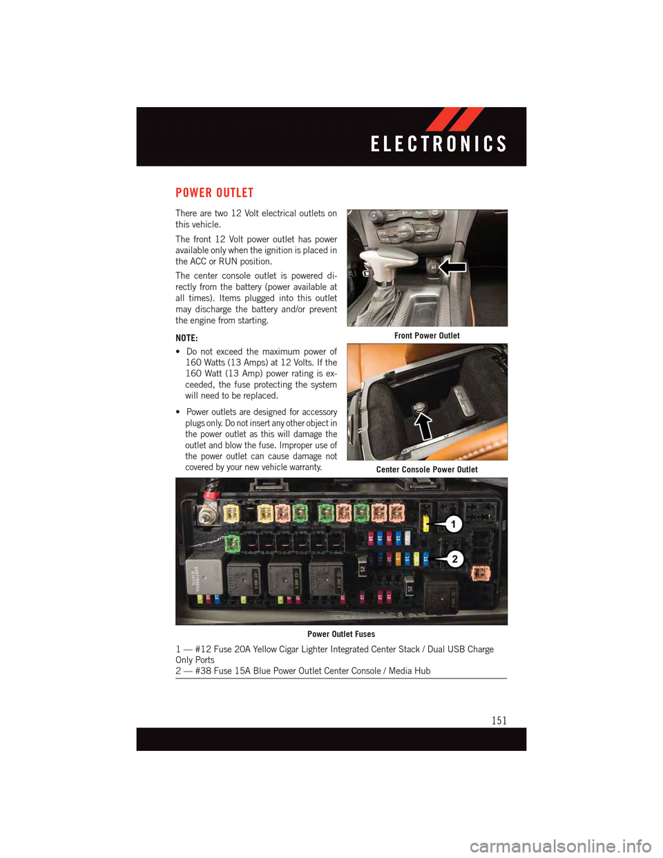
There are two 12 Volt electrical outlets on
this vehicle.
The front 12 Volt power outlet has power
available only when the ignition is placed in
the ACC or RUN position.
The center console outlet is powered di-
rectly from the battery (power available at
all times). Items plugged into this outlet
may discharge the battery and/or prevent
the engine from starting.
NOTE:
•Donotexceedthemaximumpowerof
160 Watts (13 Amps) at 12 Volts. If the
160 Watt (13 Amp) power rating is ex-
ceeded, the fuse protecting the system
will need to be replaced.
•Power outlets are designed for accessory
plugs only. Do not insert any other object in
the power outlet as this will damage the
outlet and blow the fuse. Improper use of
the power outlet can cause damage not
covered by your new vehicle warranty.
Front Power Outlet
Center Console Power Outlet
Power Outlet Fuses
1—#12Fuse20AYellowCigarLighterIntegratedCenterStack/DualUSBChargeOnly Ports2—#38Fuse15ABluePowerOutletCenterConsole/MediaHub
ELECTRONICS
151
Page 162 of 236
Electronic Throttle Control (ETC) Indicator Light
This light informs you of a problem with the system.
If a problem is detected, the light will come on while the engine is running. Cycle the
ignition when the vehicle has completely stopped and the shift lever is placed in the PARK
position; the light should turn off.
If the light remains lit with the engine running, your vehicle will usually be drivable.
However, see an authorized dealer immediately. If the light is flashing when the engine is
running, immediate service is required, and you may experience reduced performance, an
elevated/rough idle or engine stall, and your vehicle may require towing.
Tire Pressure Monitoring System (TPMS) Light
Each tire, including the spare (if provided), should be checked monthly when cold and
inflated to the inflation pressure recommended by the vehicle manufacturer on the
vehicle placard or tire inflation pressure label. (If your vehicle has tires of a different size
than the size indicated on the vehicle placard or tire inflation pressure label, you should
determine the proper tire inflation pressure for those tires).
As an added safety feature, your vehicle has been equipped with a tire pressure
monitoring system (TPMS) that illuminates a low tire pressure telltale when one or more
of your tires is significantly under-inflated. Accordingly, when the low tire pressure telltale
illuminates, you should stop and check your tires as soon as possible and inflate them to
the proper pressure. Driving on a significantly under-inflated tire causes the tire to
overheat and can lead to tire failure. Under-inflation also reduces fuel efficiency and tire
tread life and may affect the vehicle’s handling and stopping ability.
IF THE LIGHT STARTS FLASHING INDICATING A LOW TIRE PRESSURE, ADJUST THE AIR
PRESSURE IN THE LOW TIRE TO THE AIR PRESSURE SHOWN ON THE VEHICLE PLACARD OR
TIRE INFLATION PRESSURE LABEL LOCATED ON THE DRIVER'S DOOR.
NOTE:
AFTER INFLATION, THE VEHICLE MAY NEED TO BE DRIVEN FOR 20 MINUTES
BEFORE THE FLASHING LIGHT WILL TURN OFF.
Please note that the TPMS is not a substitute for proper tire maintenance, and it is the
driver’s responsibility to maintain correct tire pressure, even if under-inflation has not
reached the level to trigger illumination of the TPMS low tire pressure telltale.
Yo u r v e h i c l e h a s a l s o b e e n e q u i p p e d w i t h a T P M S m a l f u n c t i o n i n d i c a t o r t o i n d i c a t e w h e n
the system is not operating properly. The TPMS malfunction indicator is combined with
the low tire pressure telltale.
WHAT TO DO IN EMERGENCIES
160
Page 164 of 236
Electronic Stability Control (ESC) Activation/Malfunction Indicator Light
The “ESC Activation/Malfunction Indicator Light” in the instrument cluster will come on
when the ignition switch is turned to the ON/RUN position. It should go out with the
engine running. If the “ESC Activation/Malfunction Indicator Light” comes on continu-
ously with the engine running, a malfunction has been detected in the ESC system.
If this light remains on after several ignition cycles, and the vehicle has been driven
several miles (kilometers) at speeds greater than 30 mph (48 km/h), we recommend you
drive to the nearest service center and have the vehicle serviced immediately.
Brake Warning Light
This light monitors various brake functions, including brake fluid level and parking brake
application. If the brake light turns on, it may indicate that the parking brake is applied,
that the brake fluid level is low, or that there is a problem with the anti-lock brake system
reservoir.
If the light remains on when the parking brake has been disengaged, and the fluid level is
at the full mark on the master cylinder reservoir, it indicates a possible brake hydraulic
system malfunction or that a problem with the Brake Booster has been detected by the
Anti-Lock Brake System (ABS)/Electronic Stability Control (ESC) system. In this case, the
light will remain on until the condition has been corrected. If the problem is related to the
brake booster, the ABS pump will run when applying the brake, and a brake pedal
pulsation may be felt during each stop.
The dual brake system provides a reserve braking capacity in the event of a failure to a
portion of the hydraulic system. A leak in either half of the dual brake system is indicated
by the Brake Warning Light, which will turn on when the brake fluid level in the master
cylinder has dropped below a specified level. The light will remain on until the cause is
corrected.
Vehicles equipped with the Anti-Lock Brake System (ABS) are also equipped with
Electronic Brake Force Distribution (EBD). In the event of an EBD failure, the Brake
Warning Light will turn on along with the ABS Light. Immediate repair to the ABS system
is required.
Operation of the Brake Warning Light can be checked by turning the ignition switch from
the OFF position to the ON/RUN position. The light should illuminate for approximately
two seconds. The light should then turn off unless the parking brake is applied or a brake
fault is detected. If the light does not illuminate, have the light inspected by an authorized
dealer.
The light also will turn on when the parking brake is applied with the ignition switch in the
ON/RUN position.
NOTE:
This light shows only that the parking brake is applied. It does not show the degree of
brake application.
WHAT TO DO IN EMERGENCIES
162
Page 165 of 236

WARNING!
Driving a vehicle with the red brake light on is dangerous. Part of the brake system may
have failed. It will take longer to stop the vehicle. You could have a collision. Have the
vehicle checked immediately.
Malfunction Indicator Light (MIL)
Certain conditions, such as a poor fuel quality, etc., may illuminate the MIL after engine
start. The vehicle should be serviced if the light stays on through several typical driving
cycles. In most situations, the vehicle will drive normally and not require towing.
If the MIL flashes when the engine is running, serious conditions may exist that could lead
to immediate loss of power or severe catalytic converter damage. We recommend you do
not operate the vehicle. Have the vehicle serviced immediately.
Electronic Stability Control (ESC) OFF Indicator Light
This light indicates the Electronic Stability Control (ESC) is off.
INSTRUMENT CLUSTER INDICATOR LIGHTS
Turn Signal Indicator
The arrows will flash with the exterior turn signals when the turn signal lever is operated.
Atonewillchime,andaDIDmessagewillappearifeitherturnsignalisleftonformore
than 1 mile (1.6 km).
NOTE:
If either indicator flashes at a rapid rate, check for a defective outside light bulb.
High Beam Indicator
Indicates that headlights are on high beam.
Front Fog Light Indicator
This indicator will illuminate when the front fog lights are on.
Vehicle Security Light
This light will flash rapidly for approximately 15 seconds when the vehicle security alarm
is arming. The light will flash at a slower speed continuously after the alarm is set. The
security light will also come on for about three seconds when the ignition is first turned on.
Electronic Speed Control Set
Indicates that the Electronic Speed Control has been set.
WHAT TO DO IN EMERGENCIES
163
Page 166 of 236
-AdaptiveCruiseControl(ACC)ONIndicator
•If your vehicle is equipped with adaptive cruise control, the controls operate exactly the
same as the normal (fixed speed) cruise control with one difference. You can set a
specified distance you would like to maintain between you and the vehicle in front of you.
•IftheACCsensordetectsavehicleahead,ACCwillapplylimitedbrakingoraccelera-
tion automatically to maintain a preset following distance, while matching the speed of
the vehicle ahead.
•If the sensor does not detect a vehicle ahead of you, ACC will maintain a fixed set speed.
•Referto“SpeedControl”in“OperatingYourVehicle”forfurtherinformationon
Adaptive Cruise Control (ACC) ON operation and proper use.
NOTE:
Adaptive Cruise Control (ACC) increases the driving convenience provided by cruise
control while traveling on highways and major roadways. However, it is not a safety system
and not designed to prevent collisions.
Electronic Stability Control (ESC) OFF Indicator Light
This light indicates the Electronic Stability Control (ESC) is off.
-DoorAjarIndicator
This indicator will illuminate when a door(s) is left ajar and not fully closed.
Oil Change Due
Yo u r v e h i c l e i s e q u i p p e d w i t h a n e n g i n e o i l c h a n g e i n d i c a t o r s y s t e m . T h e “ O i l C h a n g e
Due” message will display for 5 seconds along with a single chime to indicate the next
scheduled oil change interval. The engine oil change indicator system is duty cycle based,
which means the engine oil change interval may fluctuate dependent upon your personal
driving style.
Resetting The Light After Servicing
Vehicles Equipped With Keyless Enter-N-Go™
1. Without pushing the brake pedal, push the ENGINE START/STOP button and cycle the
ignition to the ON/RUN position (do not start the engine).
2. Fully depress the accelerator pedal, slowly, three times within 10 seconds.
3. Without pushing the brake pedal, push the ENGINE START/STOP button once to
return the ignition to the OFF/LOCK position.
Vehicles Not Equipped With Keyless Enter-N-Go™
1. Turn the ignition switch to the ON/RUN position (do not start the engine).
2. Fully depress the accelerator pedal, slowly, three times within 10 seconds.
3. Turn the ignition switch to the OFF/LOCK position.
WHAT TO DO IN EMERGENCIES
164