ignition DODGE CHARGER 2015 7.G User Guide
[x] Cancel search | Manufacturer: DODGE, Model Year: 2015, Model line: CHARGER, Model: DODGE CHARGER 2015 7.GPages: 236, PDF Size: 35.67 MB
Page 6 of 236
VEHICLES SOLD IN CANADA
With respect to any vehicles sold in Canada, the name FCA US LLC shall be deemed to be
deleted and the name Chrysler Canada Inc. used in substitution (excluding legal lines).
WARNING!
•Pedalsthatcannotmovefreelycancauselossofvehiclecontrolandincreasethe
risk of serious personal injury.
•Alwaysmakesurethatobjectscannotfallintothedriverfootwellwhilethevehicle
is moving. Objects can become trapped under the brake pedal and accelerator
pedal causing a loss of vehicle control.
•Failuretoproperlyfollowfloormatinstallationormountingcancauseinterference
with the brake pedal and accelerator pedal operation causing loss of control of the
vehicle.
•Neverleavechildrenaloneinavehicle,orwithaccesstoanunlockedvehicle.
Allowing children to be in a vehicle unattended is dangerous for a number of
reasons. A child or others could be seriously or fatally injured. Children should be
warned not to touch the parking brake, brake pedal or the shift lever/transmission
gear selector.
•Donotleavethekeyfobinornearthevehicle,orinalocationaccessibletochildren,
and do not leave the ignition of a vehicle equipped with Keyless Enter-N-Go in the
ACC or ON/RUN mode. A child could operate power windows, other controls, or
move the vehicle.
•Never use the “PARK” position as a substitute for the parking brake. Always apply the
parking brake fully when parked to guard against vehicle movement and possible injury
or damage.
•RefertoyourOwner'sManualontheDVDforfurtherdetails.
INTRODUCTION/WELCOME
4
Page 15 of 236
WARNING!
•NeverusethePARKpositionasasubstitutefortheparkingbrake.Alwaysapplythe
parking brake fully when parked to guard against vehicle movement and possible
injury or damage.
•Whenleavingthevehicle,alwaysmakesuretheKeylessIgnitionNodeisinthe
“OFF” mode and remove the Key Fob from the vehicle.
•Neverleavechildrenaloneinavehicle,orwithaccesstoanunlockedvehicle.
Allowing children to be in a vehicle unattended is dangerous for a number of
reasons. A child or others could be seriously or fatally injured. Children should be
warned not to touch the parking brake, brake pedal or the gear selector.
•DonotleavetheKeyFobinornearthevehicle,orinalocationaccessibleto
children, and do not leave the ignition of a vehicle equipped with Keyless
Enter-N-Go™ in the ACC or ON/RUN mode. A child could operate power windows,
other controls, or move the vehicle.
REMOTE START
•PushtheREMOTESTARTbuttonx2on the Key Fob twice within five seconds.
Pushing the REMOTE START button a third time shuts the engine off.
•Todrivethevehicle,pushtheUNLOCKbuttonandcycletheignitiontotheON/RUN
position.
With Remote Start, the engine will only run for 15 minutes (timeout) unless the ignition
is cycled to the ON/RUN position.
The vehicle must be cycled to the ON/RUN position after two consecutive timeouts.
WARNING!
•Donotstartorrunanengineinaclosedgarageorconfinedarea.Exhaustgas
contains Carbon Monoxide (CO) which is odorless and colorless. Carbon Monoxide
is poisonous and can cause you or others to be severely injured or killed when
inhaled.
•KeepKeyFobtransmittersawayfromchildren.OperationoftheRemoteStart
System, windows, door locks or other controls could cause you and others to be
severely injured or killed.
GETTING STARTED
13
Page 18 of 236
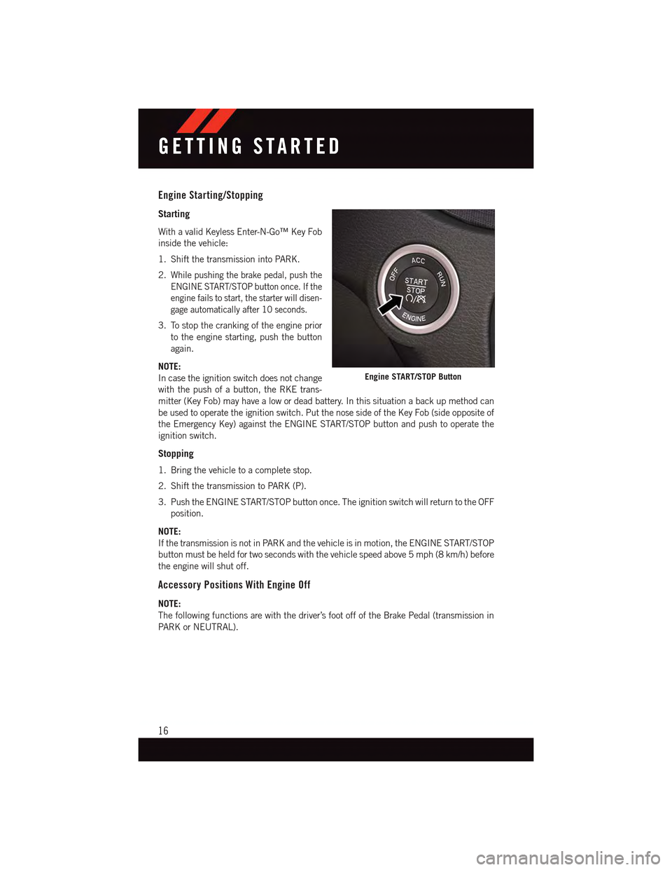
Engine Starting/Stopping
Starting
With a valid Keyless Enter-N-Go™ Key Fob
inside the vehicle:
1. Shift the transmission into PARK.
2.While pushing the brake pedal, push the
ENGINE START/STOP button once. If the
engine fails to start, the starter will disen-
gage automatically after 10 seconds.
3. To stop the cranking of the engine prior
to the engine starting, push the button
again.
NOTE:
In case the ignition switch does not change
with the push of a button, the RKE trans-
mitter (Key Fob) may have a low or dead battery. In this situation a back up method can
be used to operate the ignition switch. Put the nose side of the Key Fob (side opposite of
the Emergency Key) against the ENGINE START/STOP button and push to operate the
ignition switch.
Stopping
1. Bring the vehicle to a complete stop.
2. Shift the transmission to PARK (P).
3. Push the ENGINE START/STOP button once. The ignition switch will return to the OFF
position.
NOTE:
If the transmission is not in PARK and the vehicle is in motion, the ENGINE START/STOP
button must be held for two seconds with the vehicle speed above 5 mph (8 km/h) before
the engine will shut off.
Accessory Positions With Engine Off
NOTE:
The following functions are with the driver’s foot off of the Brake Pedal (transmission in
PA R K o r N E U T R A L ) .
Engine START/STOP Button
GETTING STARTED
16
Page 19 of 236
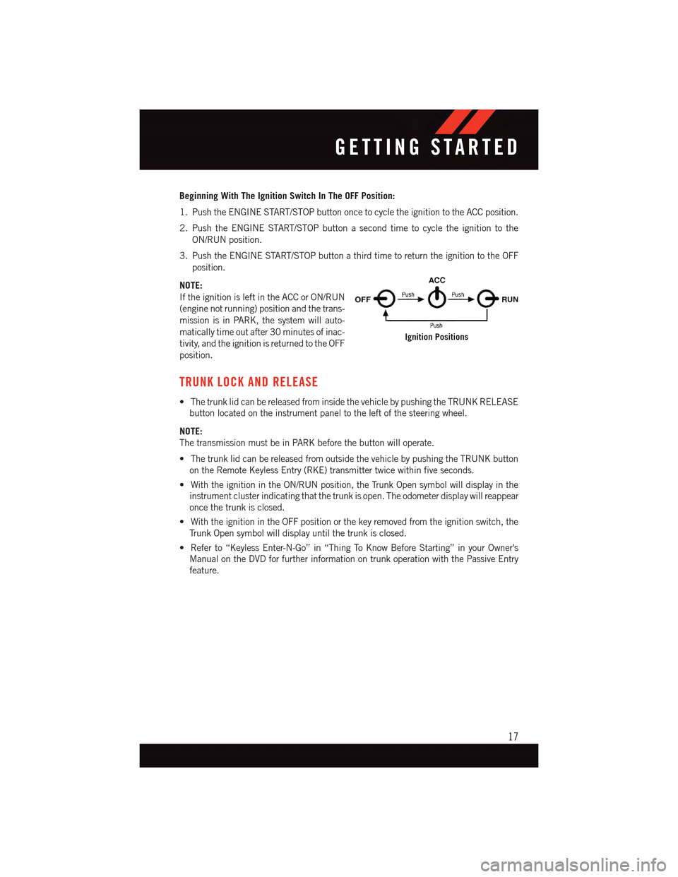
Beginning With The Ignition Switch In The OFF Position:
1. Push the ENGINE START/STOP button once to cycle the ignition to the ACC position.
2. Push the ENGINE START/STOP button a second time to cycle the ignition to the
ON/RUN position.
3. Push the ENGINE START/STOP button a third time to return the ignition to the OFF
position.
NOTE:
If the ignition is left in the ACC or ON/RUN
(engine not running) position and the trans-
mission is in PARK, the system will auto-
matically time out after 30 minutes of inac-
tivity, and the ignition is returned to the OFF
position.
TRUNK LOCK AND RELEASE
•ThetrunklidcanbereleasedfrominsidethevehiclebypushingtheTRUNKRELEASE
button located on the instrument panel to the left of the steering wheel.
NOTE:
The transmission must be in PARK before the button will operate.
•ThetrunklidcanbereleasedfromoutsidethevehiclebypushingtheTRUNKbutton
on the Remote Keyless Entry (RKE) transmitter twice within five seconds.
•WiththeignitionintheON/RUNposition,theTrunkOpensymbolwilldisplayinthe
instrument cluster indicating that the trunk is open. The odometer display will reappear
once the trunk is closed.
•WiththeignitionintheOFFpositionorthekeyremovedfromtheignitionswitch,the
Tr u n k O p e n s y m b o l w i l l d i s p l a y u n t i l t h e t r u n k i s c l o s e d .
•Referto“KeylessEnter-N-Go”in“ThingToKnowBeforeStarting”inyourOwner's
Manual on the DVD for further information on trunk operation with the Passive Entry
feature.
Ignition Positions
GETTING STARTED
17
Page 20 of 236
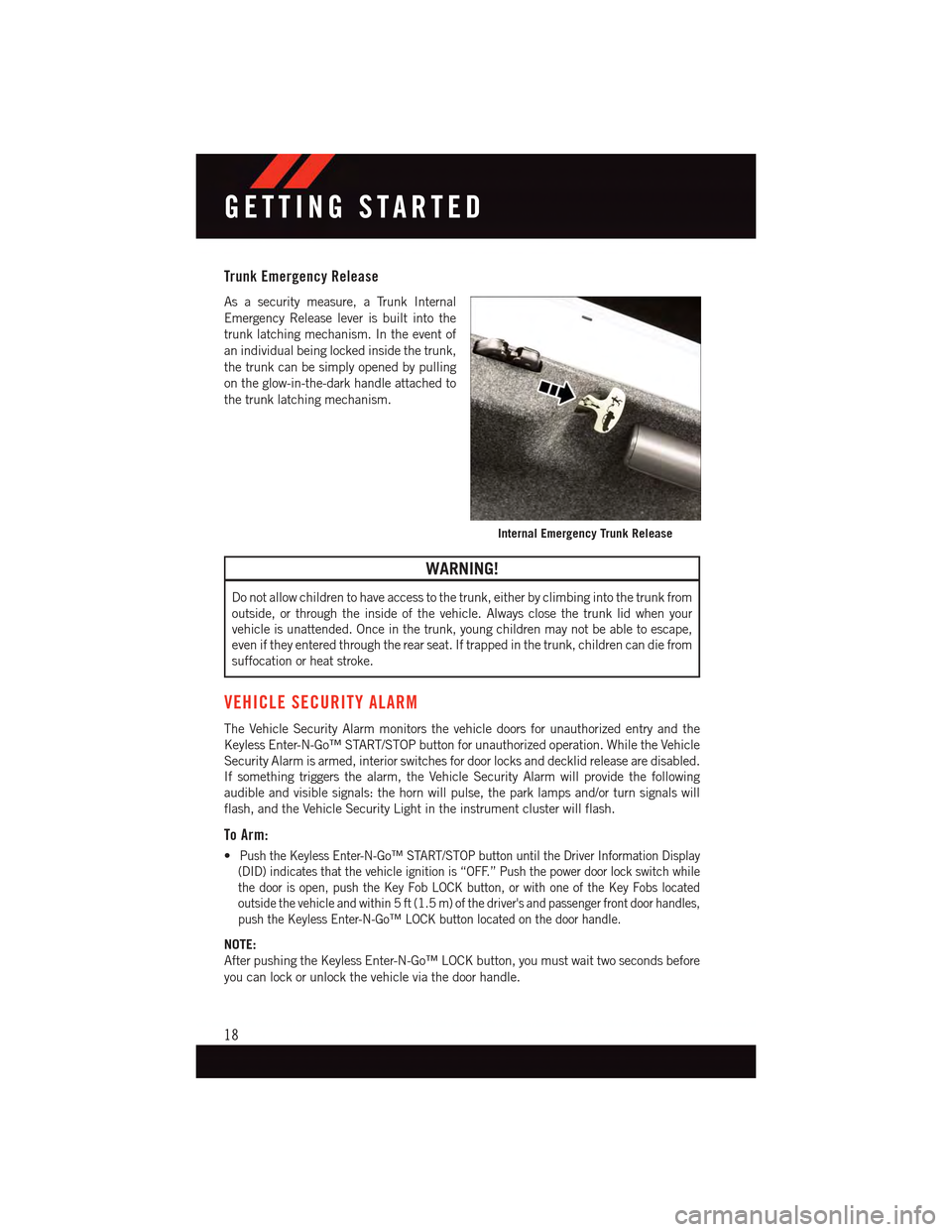
Trunk Emergency Release
As a security measure, a Trunk Internal
Emergency Release lever is built into the
trunk latching mechanism. In the event of
an individual being locked inside the trunk,
the trunk can be simply opened by pulling
on the glow-in-the-dark handle attached to
the trunk latching mechanism.
WARNING!
Do not allow children to have access to the trunk, either by climbing into the trunk from
outside, or through the inside of the vehicle. Always close the trunk lid when your
vehicle is unattended. Once in the trunk, young children may not be able to escape,
even if they entered through the rear seat. If trapped in the trunk, children can die from
suffocation or heat stroke.
VEHICLE SECURITY ALARM
The Vehicle Security Alarm monitors the vehicle doors for unauthorized entry and the
Keyless Enter-N-Go™ START/STOP button for unauthorized operation. While the Vehicle
Security Alarm is armed, interior switches for door locks and decklid release are disabled.
If something triggers the alarm, the Vehicle Security Alarm will provide the following
audible and visible signals: the horn will pulse, the park lamps and/or turn signals will
flash, and the Vehicle Security Light in the instrument cluster will flash.
To Arm:
•Push the Keyless Enter-N-Go™ START/STOP button until the Driver Information Display
(DID) indicates that the vehicle ignition is “OFF.” Push the power door lock switch while
the door is open, push the Key Fob LOCK button, or with one of the Key Fobs located
outside the vehicle and within 5 ft (1.5 m) of the driver's and passenger front door handles,
push the Keyless Enter-N-Go™ LOCK button located on the door handle.
NOTE:
After pushing the Keyless Enter-N-Go™ LOCK button, you must wait two seconds before
you can lock or unlock the vehicle via the door handle.
Internal Emergency Trunk Release
GETTING STARTED
18
Page 23 of 236
•TheORCturnsontheAirBagWarningLightintheinstrumentpanelforapproximately
four to eight seconds for a self-check when the ignition switch is first turned to the
ON/RUN position. After the self-check, the Air Bag Warning Light will turn off. If the
ORC detects a malfunction in any part of the system, it turns on the Air Bag Warning
Light, either momentarily or continuously. A single chime will sound to alert you if the
light comes on again after initial startup.
•The ORC monitors the readiness of the electronic parts of the air bag system whenever the
ignition switch is in the START or ON/RUN position. If the ignition switch is in the OFF
position or in the ACC position, the air bag system is not on and the air bags will not inflate.
•If the Air Bag Warning Light in the instrument panel is not on during the four to eight
seconds when the ignition switch is first turned to the ON/RUN position, stays on, or turns
on while driving, have the vehicle serviced by an authorized service center immediately.
NOTE:
If the speedometer, tachometer, or any engine related gauges are not working, the
Occupant Restraint Controller (ORC) may also be disabled. In this condition the air bags
may not be ready to inflate for your protection. Have an authorized dealer service the air
bag system immediately.
•Afteranycollision,thevehicleshouldbetakentoanauthorizeddealerimmediately.
•Donotdriveyourvehicleaftertheairbagshavedeployed.Ifyouareinvolvedinanother
collision, the air bags will not be in place to protect you.
•Ifitisnecessarytomodifytheairbagsystemforpersonswithdisabilities,contactyour
authorized dealer.
•RefertotheOwner'sManualontheDVDregardingtheSupplementalRestraintSystem
(SRS) for further information.
Supplemental Knee Air Bags
This vehicle is equipped with a Supplemental Driver Knee Air Bag mounted in the
instrument panel below the steering column. The Supplemental Driver Knee Air Bag
provides enhanced protection during a frontal impact by working together with the seat
belts, pretensioners, and Advanced Front Air Bags.
WARNING!
•Relyingontheairbagsalonecouldleadtomoresevereinjuriesinacollision.The
air bags work with your seat belt to restrain you properly. In some collisions, the air
bags won't deploy at all. Always wear your seat belts even though you have air bags.
•BeingtooclosetothesteeringwheelorinstrumentpanelduringAdvancedFrontAir
Bag deployment could cause serious injury, including death. Air bags need room to
inflate. Sit back, comfortably extending your arms to reach the steering wheel or
instrument panel.
•Noobjectsshouldbeplacedoverorneartheairbagontheinstrumentpanelor
steering wheel because any such objects could cause harm if the vehicle is in a
collision severe enough to cause the air bag to inflate.
GETTING STARTED
21
Page 31 of 236
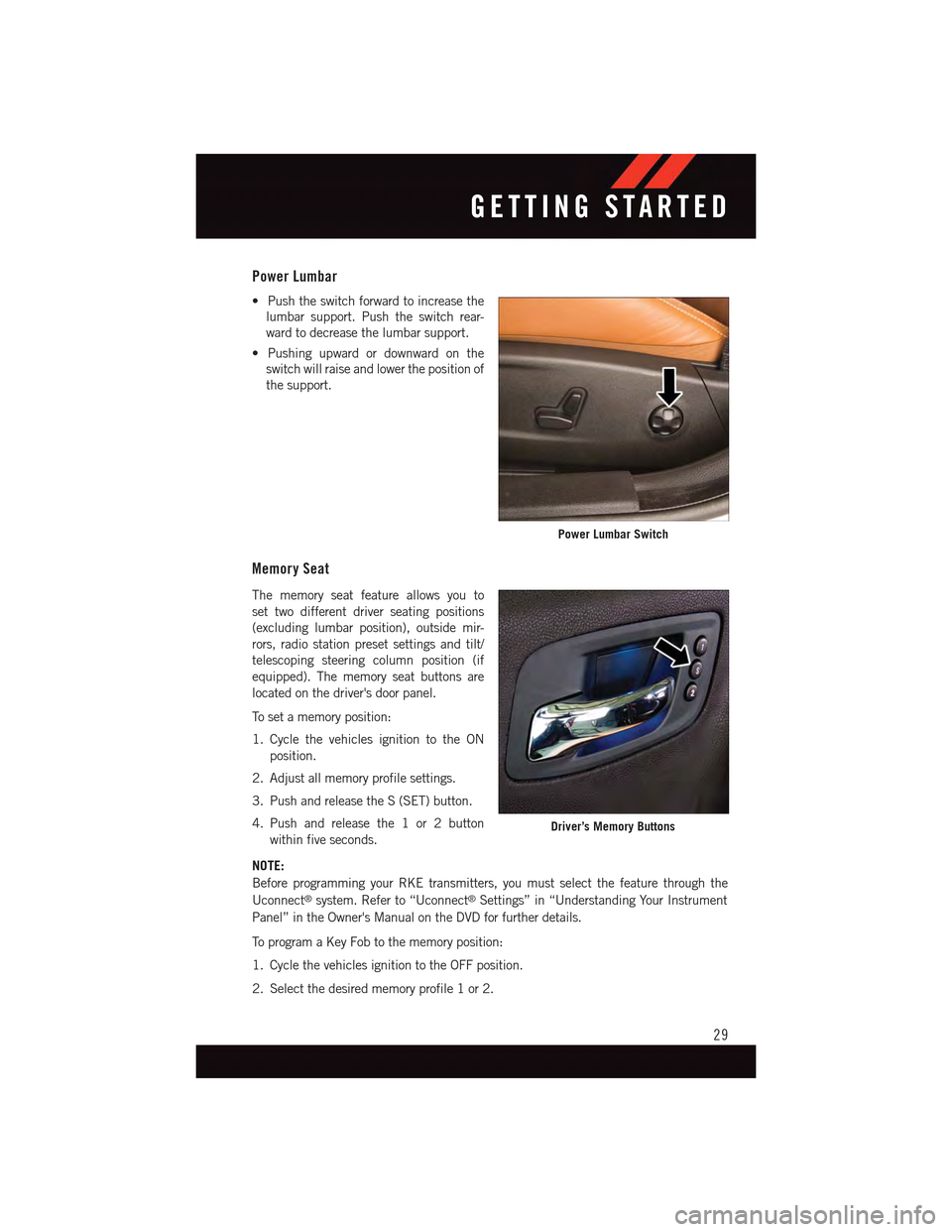
Power Lumbar
•Pushtheswitchforwardtoincreasethe
lumbar support. Push the switch rear-
ward to decrease the lumbar support.
•Pushingupwardordownwardonthe
switch will raise and lower the position of
the support.
Memory Seat
The memory seat feature allows you to
set two different driver seating positions
(excluding lumbar position), outside mir-
rors, radio station preset settings and tilt/
telescoping steering column position (if
equipped). The memory seat buttons are
located on the driver's door panel.
To s e t a m e m o r y p o s i t i o n :
1. Cycle the vehicles ignition to the ON
position.
2. Adjust all memory profile settings.
3. Push and release the S (SET) button.
4. Push and release the 1 or 2 button
within five seconds.
NOTE:
Before programming your RKE transmitters, you must select the feature through the
Uconnect®system. Refer to “Uconnect®Settings” in “Understanding Your Instrument
Panel” in the Owner's Manual on the DVD for further details.
To p r o g r a m a K e y F o b t o t h e m e m o r y p o s i t i o n :
1. Cycle the vehicles ignition to the OFF position.
2. Select the desired memory profile 1 or 2.
Power Lumbar Switch
Driver’s Memory Buttons
GETTING STARTED
29
Page 63 of 236
Closing Sunroof
Express Closing
Push the switch forward and release it within one-half second. The sunroof will fully close
automatically from any position.
Manual Closing
Push and hold the switch forward to close the sunroof. Any release of the switch will stop
the movement, and the sunroof will remain in a partially closed position until the switch
is pushed again.
Pinch Protection Feature
This feature will detect an obstruction in the opening of the sunroof during Express Close
operation. If an obstruction in the path of the sunroof is detected, the sunroof will
automatically retract. Remove the obstruction if this occurs. Next, push the switch
forward and release to Express Close.
NOTE:
If three consecutive sunroof close attempts result in Pinch Protect reversals, the fourth
close attempt will be a Manual Close movement with Pinch Protect disabled.
WARNING!
•Donotletchildrenplaywiththesunroof.Neverleavechildrenunattendedina
vehicle, or with access to an unlocked vehicle. Do not leave the Key Fob in or near
the vehicle, and do not leave the ignition of a vehicle equipped with Keyless
Enter-N-Go™ in the ACC or ON/RUN mode. Occupants, particularly unattended
children, can become entrapped by the power sunroof while operating the power
sunroof switch. Such entrapment may result in serious injury or death.
•Inacollision,thereisagreaterriskofbeingthrownfromavehiclewithanopen
sunroof. You could also be severely injured or killed. Always fasten your seat belt
properly and make sure all passengers are properly secured.
•Donotallowsmallchildrentooperatethesunroof.Neverallowyourfingers,other
body parts, or any object to project through the sunroof opening. Injury may result.
WIND BUFFETING
Wind buffeting can be described as a helicopter-type percussion sound. If buffeting
occurs with the rear windows open, adjust the front and rear windows together.
If buffeting occurs with the sunroof open, adjust the sunroof opening, or adjust any
window. This will minimize buffeting.
OPERATING YOUR VEHICLE
61
Page 136 of 236
If the Uconnect®Phone Buttonexists on your steering wheel, you then have the
Uconnect®Phone features.
Refer to theUnderstand The Features Of Your Vehiclesection of your vehicle's Owner's
Manual on the DVD for further details.
NOTE:
•TheUconnect®Phone requires a mobile phone equipped with the Bluetooth®
Hands-Free Profile, Version 1.0 or higher.
•Mostmobilephones/devicesarecompatiblewiththeUconnect®system, however
some mobile phones/devices may not be equipped with all of the required features to
utilize all of the Uconnect®system features.
•ForUconnect®Customer Care:
•U.S.residentsvisitUconnectPhone.comorcall1-877-855-8400.
•CanadianResidentsvisitUconnectPhone.comorcall,1-800-465-2001(English)or
1-800-387-9983 (French).
Pairing (Wirelessly Connecting) Your Mobile Phone To The Uconnect® System
Mobile phone pairing is the process of establishing a wireless connection between a
cellular phone and the Uconnect®system.
NOTE:
•To u s e t h e U c o n n e c t®Phone feature, you first must determine if your mobile phone and
software are compatible with the Uconnect®system. Please visitUconnectPhone.com for
complete mobile phone compatibility information.
•Mobilephonepairingisnotavailablewhilethevehicleisinmotion.
•Amaximumof10mobilephonescanbepairedtotheUconnect®system.
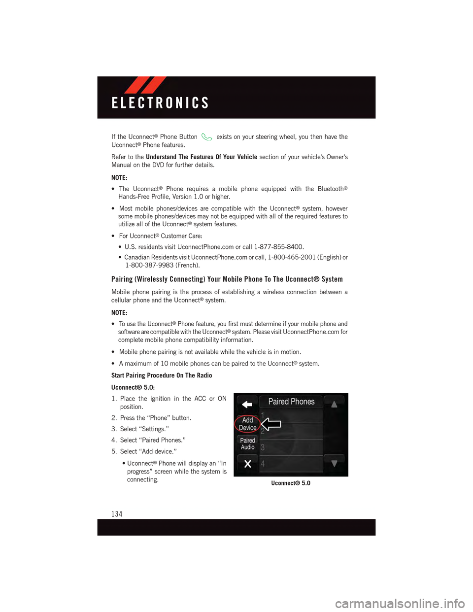
Start Pairing Procedure On The Radio
Uconnect® 5.0:
1. Place the ignition in the ACC or ON
position.
2. Press the “Phone” button.
3. Select “Settings.”
4. Select “Paired Phones.”
5. Select “Add device.”
•Uconnect®Phone will display an “In
progress” screen while the system is
connecting.Uconnect® 5.0
ELECTRONICS
134
Page 137 of 236
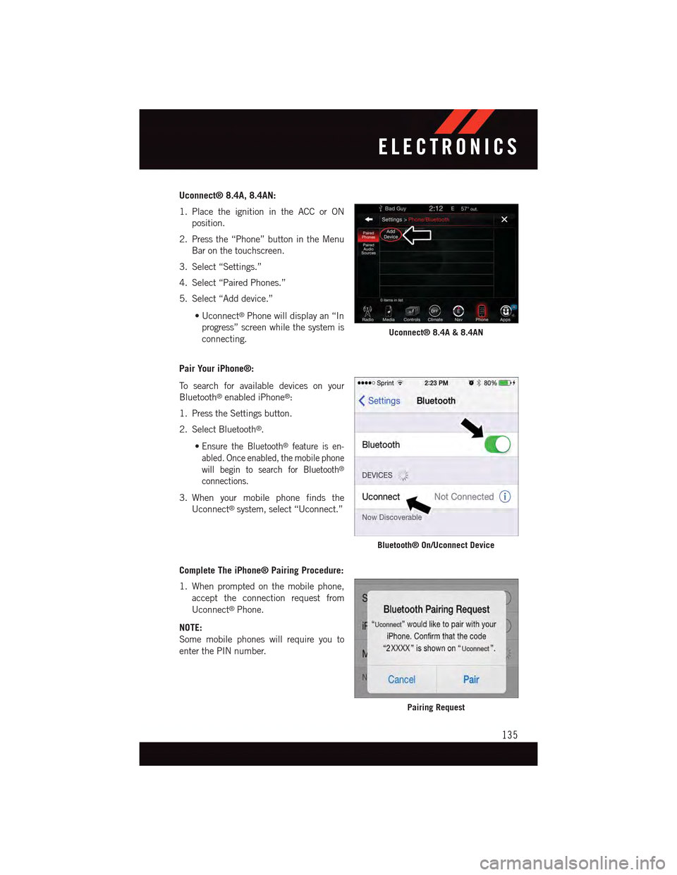
Uconnect® 8.4A, 8.4AN:
1. Place the ignition in the ACC or ON
position.
2. Press the “Phone” button in the Menu
Bar on the touchscreen.
3. Select “Settings.”
4. Select “Paired Phones.”
5. Select “Add device.”
•Uconnect®Phone will display an “In
progress” screen while the system is
connecting.
Pair Your iPhone®:
To s e a r c h f o r a v a i l a b l e d e v i c e s o n y o u r
Bluetooth®enabled iPhone®:
1. Press the Settings button.
2. Select Bluetooth®.
•Ensure the Bluetooth®feature is en-
abled. Once enabled, the mobile phone
will begin to search for Bluetooth®
connections.
3. When your mobile phone finds the
Uconnect®system, select “Uconnect.”
Complete The iPhone® Pairing Procedure:
1. When prompted on the mobile phone,
accept the connection request from
Uconnect®Phone.
NOTE:
Some mobile phones will require you to
enter the PIN number.
Uconnect® 8.4A & 8.4AN
Bluetooth® On/Uconnect Device
Pairing Request
ELECTRONICS
135