warning light DODGE CHARGER 2015 7.G Owner's Manual
[x] Cancel search | Manufacturer: DODGE, Model Year: 2015, Model line: CHARGER, Model: DODGE CHARGER 2015 7.GPages: 236, PDF Size: 35.67 MB
Page 161 of 236
ROADSIDE ASSISTANCE
Dial toll-free 1-800-521-2779 for U.S. Residents or 1-800-363-4869 for Canadian
Residents.
•Provideyourname,vehicleidentificationnumber,licenseplatenumber,andyour
location, including the telephone number from which you are calling.
•Brieflydescribethenatureoftheproblemandanswerafewsimplequestions.
•Youwillbegiventhenameoftheserviceproviderandanestimatedtimeofarrival.
If you feel you are in an “unsafe situation”, please let us know. With your consent, we
will contact local police or safety authorities.
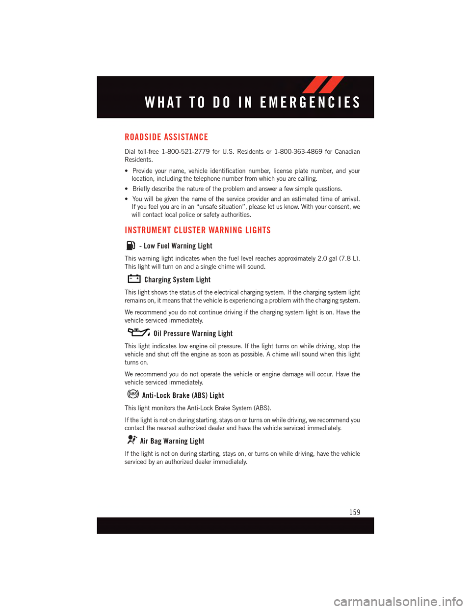
INSTRUMENT CLUSTER WARNING LIGHTS
-LowFuelWarningLight
This warning light indicates when the fuel level reaches approximately 2.0 gal (7.8 L).
This light will turn on and a single chime will sound.
Charging System Light
This light shows the status of the electrical charging system. If the charging system light
remains on, it means that the vehicle is experiencing a problem with the charging system.
We recommend you do not continue driving if the charging system light is on. Have the
vehicle serviced immediately.
Oil Pressure Warning Light
This light indicates low engine oil pressure. If the light turns on while driving, stop the
vehicle and shut off the engine as soon as possible. A chime will sound when this light
turns on.
We recommend you do not operate the vehicle or engine damage will occur. Have the
vehicle serviced immediately.
Anti-Lock Brake (ABS) Light
This light monitors the Anti-Lock Brake System (ABS).
If the light is not on during starting, stays on or turns on while driving, we recommend you
contact the nearest authorized dealer and have the vehicle serviced immediately.
Air Bag Warning Light
If the light is not on during starting, stays on, or turns on while driving, have the vehicle
serviced by an authorized dealer immediately.
WHAT TO DO IN EMERGENCIES
159
Page 163 of 236
When the system detects a malfunction, the telltale will flash for approximately one
minute and then remain continuously illuminated. This sequence will continue upon
subsequent vehicle start-ups as long as the malfunction exists. When the malfunction
indicator is illuminated, the system may not be able to detect or signal low tire pressure
as intended. TPMS malfunctions may occur for a variety of reasons, including the
installation of replacement or alternate tires or wheels on the vehicle that prevent the
TPMS from functioning properly. Always check the TPMS malfunction telltale after
replacing one or more tires or wheels on your vehicle to ensure that the replacement or
alternate tires and wheels allow the TPMS to continue to function properly.
NOTE:
Ti r e p r e s s u r e s c h a n g e b y a p p r o x i m a t e l y 1 p s i ( 7 k P a ) p e r 1 2 ° F ( 7 ° C ) o f a i r t e m p e r a t u r e
change. Keep this in mind when checking tire pressure inside a garage, especially in the
Winter. Example: If garage temperature is 68°F (20°C), and the outside temperature is
32°F (0°C), then the cold tire inflation pressure should be increased by 3 psi (21 kPa),
which equals 1 psi (7 kPa) for every 12°F (7°C) for this outside temperature condition.
CAUTION!
The TPMS has been optimized for the original equipment tires and wheels. TPMS
pressures and warning have been established for the tire size equipped on your vehicle.
Undesirable system operation or sensor damage may result when using replacement
equipment that is not of the same size, type, and/or style. Aftermarket wheels can
cause sensor damage. Do not use tire sealant from a can, or balance beads if your
vehicle is equipped with a TPMS, as damage to the sensors may result.
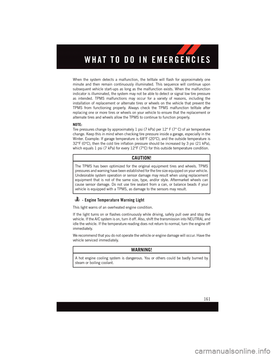
-EngineTemperatureWarningLight
This light warns of an overheated engine condition.
If the light turns on or flashes continuously while driving, safely pull over and stop the
vehicle. If the A/C system is on, turn it off. Also, shift the transmission into NEUTRAL and
idle the vehicle. If the temperature reading does not return to normal, turn the engine off
immediately.
We recommend that you do not operate the vehicle or engine damage will occur. Have the
vehicle serviced immediately.
WARNING!
Ahotenginecoolingsystemisdangerous.Youorotherscouldbebadlyburnedby
steam or boiling coolant.
WHAT TO DO IN EMERGENCIES
161
Page 164 of 236
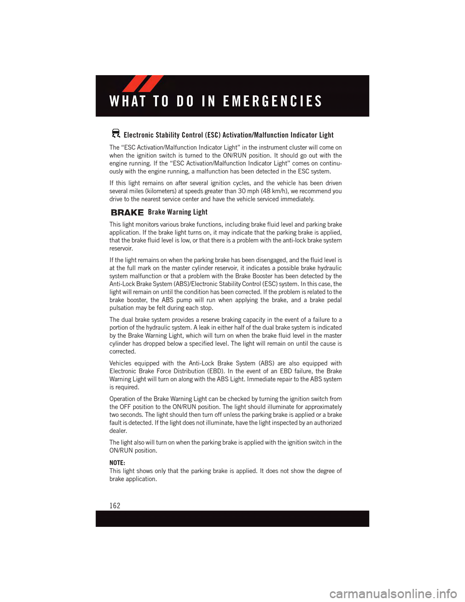
Electronic Stability Control (ESC) Activation/Malfunction Indicator Light
The “ESC Activation/Malfunction Indicator Light” in the instrument cluster will come on
when the ignition switch is turned to the ON/RUN position. It should go out with the
engine running. If the “ESC Activation/Malfunction Indicator Light” comes on continu-
ously with the engine running, a malfunction has been detected in the ESC system.
If this light remains on after several ignition cycles, and the vehicle has been driven
several miles (kilometers) at speeds greater than 30 mph (48 km/h), we recommend you
drive to the nearest service center and have the vehicle serviced immediately.
Brake Warning Light
This light monitors various brake functions, including brake fluid level and parking brake
application. If the brake light turns on, it may indicate that the parking brake is applied,
that the brake fluid level is low, or that there is a problem with the anti-lock brake system
reservoir.
If the light remains on when the parking brake has been disengaged, and the fluid level is
at the full mark on the master cylinder reservoir, it indicates a possible brake hydraulic
system malfunction or that a problem with the Brake Booster has been detected by the
Anti-Lock Brake System (ABS)/Electronic Stability Control (ESC) system. In this case, the
light will remain on until the condition has been corrected. If the problem is related to the
brake booster, the ABS pump will run when applying the brake, and a brake pedal
pulsation may be felt during each stop.
The dual brake system provides a reserve braking capacity in the event of a failure to a
portion of the hydraulic system. A leak in either half of the dual brake system is indicated
by the Brake Warning Light, which will turn on when the brake fluid level in the master
cylinder has dropped below a specified level. The light will remain on until the cause is
corrected.
Vehicles equipped with the Anti-Lock Brake System (ABS) are also equipped with
Electronic Brake Force Distribution (EBD). In the event of an EBD failure, the Brake
Warning Light will turn on along with the ABS Light. Immediate repair to the ABS system
is required.
Operation of the Brake Warning Light can be checked by turning the ignition switch from
the OFF position to the ON/RUN position. The light should illuminate for approximately
two seconds. The light should then turn off unless the parking brake is applied or a brake
fault is detected. If the light does not illuminate, have the light inspected by an authorized
dealer.
The light also will turn on when the parking brake is applied with the ignition switch in the
ON/RUN position.
NOTE:
This light shows only that the parking brake is applied. It does not show the degree of
brake application.
WHAT TO DO IN EMERGENCIES
162
Page 165 of 236

WARNING!
Driving a vehicle with the red brake light on is dangerous. Part of the brake system may
have failed. It will take longer to stop the vehicle. You could have a collision. Have the
vehicle checked immediately.
Malfunction Indicator Light (MIL)
Certain conditions, such as a poor fuel quality, etc., may illuminate the MIL after engine
start. The vehicle should be serviced if the light stays on through several typical driving
cycles. In most situations, the vehicle will drive normally and not require towing.
If the MIL flashes when the engine is running, serious conditions may exist that could lead
to immediate loss of power or severe catalytic converter damage. We recommend you do
not operate the vehicle. Have the vehicle serviced immediately.
Electronic Stability Control (ESC) OFF Indicator Light
This light indicates the Electronic Stability Control (ESC) is off.
INSTRUMENT CLUSTER INDICATOR LIGHTS
Turn Signal Indicator
The arrows will flash with the exterior turn signals when the turn signal lever is operated.
Atonewillchime,andaDIDmessagewillappearifeitherturnsignalisleftonformore
than 1 mile (1.6 km).
NOTE:
If either indicator flashes at a rapid rate, check for a defective outside light bulb.
High Beam Indicator
Indicates that headlights are on high beam.
Front Fog Light Indicator
This indicator will illuminate when the front fog lights are on.
Vehicle Security Light
This light will flash rapidly for approximately 15 seconds when the vehicle security alarm
is arming. The light will flash at a slower speed continuously after the alarm is set. The
security light will also come on for about three seconds when the ignition is first turned on.
Electronic Speed Control Set
Indicates that the Electronic Speed Control has been set.
WHAT TO DO IN EMERGENCIES
163
Page 172 of 236
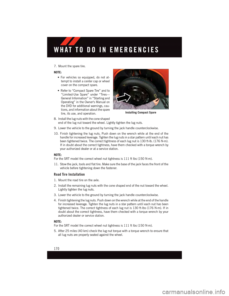
7. Mount the spare tire.
NOTE:
•Forvehiclessoequipped,donotat-
tempt to install a center cap or wheel
cover on the compact spare.
•Referto“CompactSpareTire”andto
“Limited-Use Spare” under “Tires—
General Information” in “Starting and
Operating” in the Owner's Manual on
the DVD for additional warnings, cau-
tions, and information about the spare
tire, its use, and operation.
8. Install the lug nuts with the cone shaped
end of the lug nut toward the wheel. Lightly tighten the lug nuts.
9. Lower the vehicle to the ground by turning the jack handle counterclockwise.
10. Finish tightening the lug nuts. Push down on the wrench while at the end of the
handle for increased leverage. Tighten the lug nuts in a star pattern until each nut has
been tightened twice. The correct tightness of each lug nut is 130 ft-lb. (176 N·m).
If in doubt about the correct tightness, have them checked with a torque wrench by
your authorized dealer or at a service station.
NOTE:
For the SRT model the correct wheel nut tightness is 111 ft lbs (150 N·m).
11. Stow the jack, tools and flat tire. Make sure the base of the jack faces the front of the
vehicle before tightening down the fastener.
Road Tire Installation
1. Mount the road tire on the axle.
2. Install the remaining lug nuts with the cone shaped end of the nut toward the wheel.
Lightly tighten the lug nuts.
3. Lower the vehicle to the ground by turning the jack handle counterclockwise.
4. Finish tightening the lug nuts. Push down on the wrench while at the end of the handle
for increased leverage. Tighten the lug nuts in a star pattern until each nut has been
tightened twice. The correct tightness of each lug nut is 130 ft-lbs (176 N·m). If in
doubt about the correct tightness, have them checked with a torque wrench by your
authorized dealer or service station.
NOTE:
For the SRT model the correct wheel nut tightness is 111 ft lbs (150 N·m).
5. After 25 miles (40 km) check the lug nut torque with a torque wrench to ensure that
all lug nuts are properly seated against the wheel.
Installing Compact Spare
WHAT TO DO IN EMERGENCIES
170
Page 187 of 236
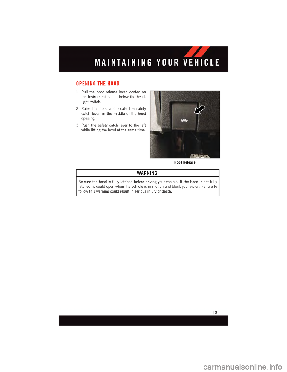
OPENING THE HOOD
1. Pull the hood release lever located on
the instrument panel, below the head-
light switch.
2. Raise the hood and locate the safety
catch lever, in the middle of the hood
opening.
3. Push the safety catch lever to the left
while lifting the hood at the same time.
WARNING!
Be sure the hood is fully latched before driving your vehicle. If the hood is not fully
latched, it could open when the vehicle is in motion and block your vision. Failure to
follow this warning could result in serious injury or death.
Hood Release
MAINTAINING YOUR VEHICLE
185
Page 200 of 236
MAINTENANCE PROCEDURES
For information on the maintenance procedures for your vehicle, please refer to “Main-
tenance Procedures” in “Maintaining Your Vehicle” in your Owner’s Manual or applicable
supplement on the DVD for further details.
MAINTENANCE SCHEDULE — NON-SRT
Yo u r v e h i c l e i s e q u i p p e d w i t h a n a u t o m a t i c o i l c h a n g e i n d i c a t o r s y s t e m . T h e o i l c h a n g e
indicator system will remind you that it is time to take your vehicle in for scheduled
maintenance.
Based on engine operation conditions, the oil change indicator message will illuminate.
This means that service is required for your vehicle. Operating conditions such as frequent
short-trips, trailer tow, extremely hot or cold ambient temperatures, and E85 fuel usage
will influence when the “Change Oil” or “Oil Change Required” message is displayed.
Severe Operating Conditions can cause the change oil message to illuminate as early as
3,500 miles (5,600 km) since last reset. Have your vehicle serviced as soon as possible,
within the next 500 miles (805 km).
The “Oil Change Required” message will be displayed in the DID and a single chime will
sound, indicating that an oil change is necessary.
Yo u r a u t h o r i z e d d e a l e r w i l l r e s e t t h e o i l c h a n g e i n d i c a t o r m e s s a g e a f t e r c o m p l e t i n g t h e
scheduled oil change. If a scheduled oil change is performed by someone other than your
authorized dealer, the message can be reset by referring to the steps described under
“Instrument Cluster Warning Lights” in “What To Do In Emergencies” in this guide or
“Driver Information Dispay (DID)” in “Understanding Your Instrument Panel” in your
Owners Manual on the DVD for further information.
NOTE:
Under no circumstances should oil change intervals exceed 10,000 miles (16,000 km)
or twelve months, whichever comes first.
MAINTAINING YOUR VEHICLE
198
Page 205 of 236
MAINTENANCE SCHEDULE — SRT
The Scheduled Maintenance services listed in this manual must be done at the times or
mileages specified to protect your vehicle warranty and ensure the best vehicle perfor-
mance and reliability. More frequent maintenance may be needed for vehicles in severe
operating conditions, such as dusty areas and very short trip driving. Inspection and
service should also be done anytime a malfunction is suspected.
The oil change indicator system will remind you that it is time to take your vehicle in forscheduled maintenance.
A“OilChangeRequired”messagewillbedisplayedintheDIDandasinglechimewillsound, indicating that an oil change is necessary.
Based on engine operation conditions, the oil change indicator message will illuminate.This means that service is required for your vehicle. Have your vehicle serviced as soon aspossible, within the next 500 miles (805 km).
NOTE:
•Theoilchangeindicatormessagewillnotmonitorthetimesincethelastoilchange.Change your vehicle's oil if it has been six months since your last oil change, even if theoil change indicator message is NOT illuminated.
•Changeyourengineoilmoreoftenifyoudriveyourvehicleoff-road/trackusageforanextended period of time.
•Undernocircumstancesshouldoilchangeintervalsexceed6,000miles(10,000km)or six months, whichever comes first.
Yo u r a u t h o r i z e d d e a l e r w i l l r e s e t t h e o i l c h a n g e i n d i c a t o r m e s s a g e a f t e r c o m p l e t i n g t h escheduled oil change. If a scheduled oil change is performed by someone other than yourauthorized dealer, the message can be reset by referring to the steps described under“Instrument Cluster Warning Lights” in “What To Do In Emergencies” in this guide or“Driver Information Display (DID)” in “Understanding Your Instrument Panel” in yourOwners Manual on the DVD for further information.
At Each Stop For Fuel
•Checktheengineoillevel.Referto“MaintenanceProcedures/EngineOil”in“Main-taining Your Vehicle” for further information.•Checkthewindshieldwashersolventandaddifrequired.
Once A Month
•Checktirepressureandlookforunusualwearordamage.
•Inspectthebattery,andcleanandtightentheterminalsasrequired.
•Checkthefluidlevelsofthecoolantreservoir,brakemastercylinder,andpowersteering
(6.2L Only), and add as needed.
•Checkalllightsandotherelectricalitemsforcorrectoperation.
At Each Oil Change
•Changetheengineoilfilter.
•Inspectthebrakehosesandlines.
CAUTION!
Failure to perform the required maintenance items may result in damage to the vehicle.
MAINTAINING YOUR VEHICLE
203
Page 223 of 236
FAQ’s
GETTING STARTED
How do I install my LATCH Equipped Child Seat? pg. 24
How do I program my Front Seat Memory? pg. 29
OPERATING YOUR VEHICLE
How does the Automatic Climate Control operate? pg. 58
ELECTRONICS
How do I know which radio I have?
•Uconnect®5.0 pg. 81
•Uconnect®8.4A, 8.4AN pg. 91
How do I select the AUX music source? pg. 97
How do I set the clock on my radio?
•Uconnect®5.0 pg. 81
•Uconnect®8.4A, 8.4AN pg. 91
How do I use the Navigation feature? pg. 100
How do I pair my cell phone via Bluetooth®with the Uconnect®Hands-Free Voice
Activation System? pg. 132
How do I configure my Universal Garage Door Opener (HomeLink)? pg. 148
How do I improve the Bluetooth®performance of my Uconnect®System? pg. 141
UTILITY
How do I know how much I can tow with my Dodge Charger? pg. 152
WHAT TO DO IN EMERGENCIES
What do I do if my TPMS warning light is blinking? pg. 160
How do I change a flat tire? pg. 166
How do I Jump-Start my vehicle? pg. 178
MAINTAINING YOUR VEHICLE
Where is my Fuse Block located? pg. 208
What type of oil do I use in my 3.6L or 5.7L engine? pg. 194
What type of oil do I use in my 6.4L or 6.2L Supercharged engine? pg. 194
How often should I change my engine’s oil? pg. 198
How often should I change my SRT engine’s oil? pg. 203
What should my tire pressure be set at? pg. 213
FREQUENTLY ASKED QUESTIONS
221
Page 224 of 236
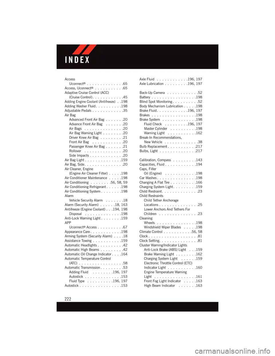
AccessUconnect®..............65Access, Uconnect®...........65Adaptive Cruise Control (ACC)(Cruise Control) . . . . . . . . . . . .45Adding Engine Coolant (Antifreeze)..198Adding Washer Fluid..........198Adjustable Pedals............35Air BagAdvanced Front Air Bag.......20Advance Front Air Bag.......20Air Bags . . . . . . . . . . . . . . .20Air Bag Warning Light . . . . . . . .20Driver Knee Air Bag.........21Front Air Bag . . . . . . . . . . . .20Passenger Knee Air Bag.......21Rollover . . . . . . . . . . . . . . .20Side Impacts.............20Air Bag Light . . . . . . . . . . . . . .159Air Bag, Side . . . . . . . . . . . . . . .20Air Cleaner, Engine(Engine Air Cleaner Filter).....198Air Conditioner Maintenance.....198Air Conditioning........56,58,59Air Conditioning Refrigerant......198Air Conditioning System........198AlarmVehicle Security Alarm.......18Alarm (Security Alarm)......18,163Antifreeze (Engine Coolant) . . .194, 198Disposal . . . . . . . . . . . . . .198Anti-Lock Warning Light........159APPUconnect®Access..........67Appearance Care............198Arming System (Security Alarm)....18Assistance Towing...........159Automatic Headlights..........42Automatic High Beams.........42Automatic Oil Change Indicator....164Automatic Temperature Control(ATC) . . . . . . . . . . . . . . . . .58Automatic Transmission.........53Adding Fluid........196, 197Autostick..............153Fluid Type . . . . . . . . . .196, 197Autostick................153
Axle Fluid . . . . . . . . . . . .196, 197Axle Lubrication . . . . . . . . .196, 197
Back-Up Camera............52Battery . . . . . . . . . . . . . . . . .198Blind Spot Monitoring..........52Body Mechanism Lubrication.....198Brake Fluid . . . . . . . . . . . .196, 197Brakes.................198Brake System.............198Fluid Check.........196, 197Master Cylinder..........198Warning Light . . . . . . . . . . .162Break-In Recommendations,New Vehicle . . . . . . . . . . . . .38Bulb Replacement...........217Bulbs, Light . . . . . . . . . . . . . .217
Calibration, Compass.........143Capacities, Fluid............194Caps, FillerOil (Engine)............198Car Washes . . . . . . . . . . . . . . .198Changing A Flat Tire..........166Charging System Light.........159Child Restraint..............23Child RestraintsChild Tether AnchorageLocations...............25Lower Anchors And Tethers ForChildren . . . . . . . . . . . . . . .23CleaningWheels...............198Windshield Wiper Blades.....198Climate Control . . . . . . . . . . .56, 58Clock . . . . . . . . . . . . . . . . . . .81Clock Setting...............81Cluster Warning/Indicator LightsAnti-Lock Brake (ABS) Light . . .159Brake Warning Light . . . . . . . .162Charging System Light......159Electronic Throttle Control (ETC)Indicator Light . . . . . . . . . . .160Engine Temperature WarningLight . . . . . . . . . . . . . . . .161Front Fog Light Indicator . . . . .163High Beam Indicator.......163
INDEX
222