ECU DODGE CHARGER 2015 7.G Owner's Manual
[x] Cancel search | Manufacturer: DODGE, Model Year: 2015, Model line: CHARGER, Model: DODGE CHARGER 2015 7.GPages: 236, PDF Size: 35.67 MB
Page 132 of 236
Taking A Detour
To t a k e a d e t o u r y o u m u s t b e n a v i g a t i n g a r o u t e .
•Pressthe“Detour”buttononthetouchscreen.
NOTE:
•Iftherouteyouarecurrentlytakingistheonlyreasonableoption,thedevicemightnot
calculate a detour.
•Formoreinformation,seeyourUconnect®Supplement Manual.
SiriusXM TRAFFIC (US Market Only)
Don't Drive Through Traffic. Drive Around It.
Avoid congestion before you reach it. By enhancing your vehicle's navigation system with
the ability to see detailed traffic information, you can pinpoint traffic incidents, determine
average traffic speed and estimate travel time along your route. Since the service is
integrated with a vehicle's navigation system, SiriusXM Traffic can help drivers pick the
fastest route based on traffic conditions.
•Detailedinformationontrafficspeed,accidents,construction,androadclosings.
•Trafficinformationfrommultiplesources,includingpoliceandemergencyservices,
cameras and road sensors.
•Coast-to-coastdeliveryoftrafficinformation.
•Viewconditionsforpointsalongyourrouteandbeyond.Availableinover130markets.
SiriusXM TRAVEL LINK (US Market Only)
In addition to delivering over 130 channels of the best sports, entertainment, talk, and
commercial-free music, SiriusXM offers premium data services that work in conjunction
with compatible navigation systems. SiriusXM Travel Link brings a wealth of useful
information into your vehicle and right to your fingertips.
•Fuel Prices—Checklocalgasanddieselpricesinyourareaandroutetothestationof
your choice.
•Movie Listings—Checklocalmovietheatresandlistingsinyourareaandroutetothe
theater of your choice.
•Sports Scores—In-gameandfinalscoresaswellasweeklyschedules.
•Weather—Checkvarietyoflocalandnationalweatherinformationfromradarmapsto
current and 5-day forecast.
ELECTRONICS
130
Page 148 of 236
Lap Timer
When selected, the Lap Timer page will show the timer always at 0:00.00 with the
previous Best and Last time data (unless the driver has cleared it via hold to Reset).
•PushingOKwill start “current” timer from 0:00.0.
•WhenOKis pushed, the times are updated accordingly.
•AssoonasthedriverexitstheLapTimerpages,the“current”timerwillstopandthe
time will be reset to 0:00.00.
•IfthedriverstaysontheLapTimerpages,the“current”timerwillresetto0:00.0when
ignition is placed in the off position, or ignition placed in the ON position (or will roll
over at 59:59.99 if ever possible).
•EachtimethedriverpushesOKfor a Lap that current time populates, the Last time and
also populates the 1st (top) space on the Timer History page the current time resets to
0:00.0 at every push of theOKbutton.
•Thetimerwillstopwhenthedrivernavigatesawayfromthispage.
Lap History
When selected, this screen displays the Lap History, and will color highlight the time that
is the best time from the Timer Page.
•EachtimethedriverpushestheOKbutton(whileontheLapTimerpage)thecurrent
Lap Time populates the 1st spot and the rest of the data shifts down.
•ColorwillindicatethetimethatisthebesttimefromtheTimerPage.
•HoldingtheOKbutton only resets the page you are on.
•LapHistorypageisastaticdisplayoflaptimesonly.
Top Speed
When selected, this screen displays the Top Speed since last reset:
•Populatesatopspeedfromfirstdrivecycleandeverytimethatspeedisexceededthat
number is stored here unless/until the driver resets the screen.
•Latchingoverignitioncycles.
•Unitswillchangewiththeglobalchangeinunits.
ELECTRONICS
146
Page 150 of 236
UNIVERSAL GARAGE DOOR OPENER
Universal Garage Door Opener (HomeLink®)
HomeLink®replaces up to three hand-held transmitters that operate devices such as
garage door openers, motorized gates, lighting or home security systems. The HomeLink®
unit is powered by your vehicles 12 Volt battery.
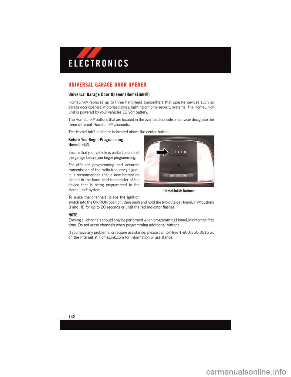
The HomeLink®buttons that are located in the overhead console or sunvisor designate the
three different HomeLink®channels.
The HomeLink®indicator is located above the center button.
Before You Begin Programming
HomeLink®
Ensure that your vehicle is parked outside of
the garage before you begin programming.
For efficient programming and accurate
transmission of the radio-frequency signal,
it is recommended that a new battery be
placed in the hand-held transmitter of the
device that is being programmed to the
HomeLink®system.
To e r a s e t h e c h a n n e l s , p l a c e t h e i g n i t i o n
switch into the ON/RUN position, then push and hold the two outside HomeLink®buttons
(I and III) for up to 20 seconds or until the red indicator flashes.
NOTE:
Erasing all channels should only be performed when programming HomeLink®for the first
time. Do not erase channels when programming additional buttons.
If you have any problems, or require assistance, please call toll-free 1-800-355-3515 or,
on the Internet at HomeLink.com for information or assistance.
HomeLink® Buttons
ELECTRONICS
148
Page 152 of 236
Programming A Non-Rolling Code
NOTE:
For programming Garage Door Openers manufactured before 1995.
1. Turn the ignition switch to the ON/RUN position.
2. Place the hand-held transmitter 1 to 3 inches (3 to 8 cm) away from the HomeLink®
button you wish to program while keeping the HomeLink®indicator light in view.
3. Push and hold the HomeLink®button you want to program while you push and hold
the hand-held transmitter button.
4. Continue to hold both buttons and observe the indicator light. The HomeLink®
indicator will flash slowly and then rapidly after HomeLink®has received the fre-
quency signal from the hand-held transmitter. Release both buttons after the indicator
light changes from slow to rapid.
5. Push and hold the programmed HomeLink®button and observe the indicator light.
If the indicator light stays on constantly, programming is complete and the garage door
(or device) should activate when the HomeLink®button is pushed.
6.To p r o g r a m t h e t w o r e m a i n i n g H o m e L i n k®buttons, repeat each step for each remaining
button. DO NOT erase the channels.
Using HomeLink®
To o p e r a t e , p u s h a n d r e l e a s e t h e p r o g r a m m e d H o m e L i n k®button. Activation will now
occur for the programmed device (e.g., garage door opener, gate operator, security system,
entry door lock, home/office lighting, etc.). The hand-held transmitter of the device may
also be used at any time.
WARNING!
•Yourmotorizeddoororgatewillopenandclosewhileyouareprogrammingthe
universal transceiver. Do not program the transceiver if people or pets are in the
path of the door or gate.
•Donotrunyourvehicleinaclosedgarageorconfinedareawhileprogrammingthe
transceiver. Exhaust gas from your vehicle contains Carbon Monoxide (CO) which is
odorless and colorless. Carbon Monoxide is poisonous when inhaled and can cause
you and others to be severely injured or killed.
ELECTRONICS
150
Page 158 of 236
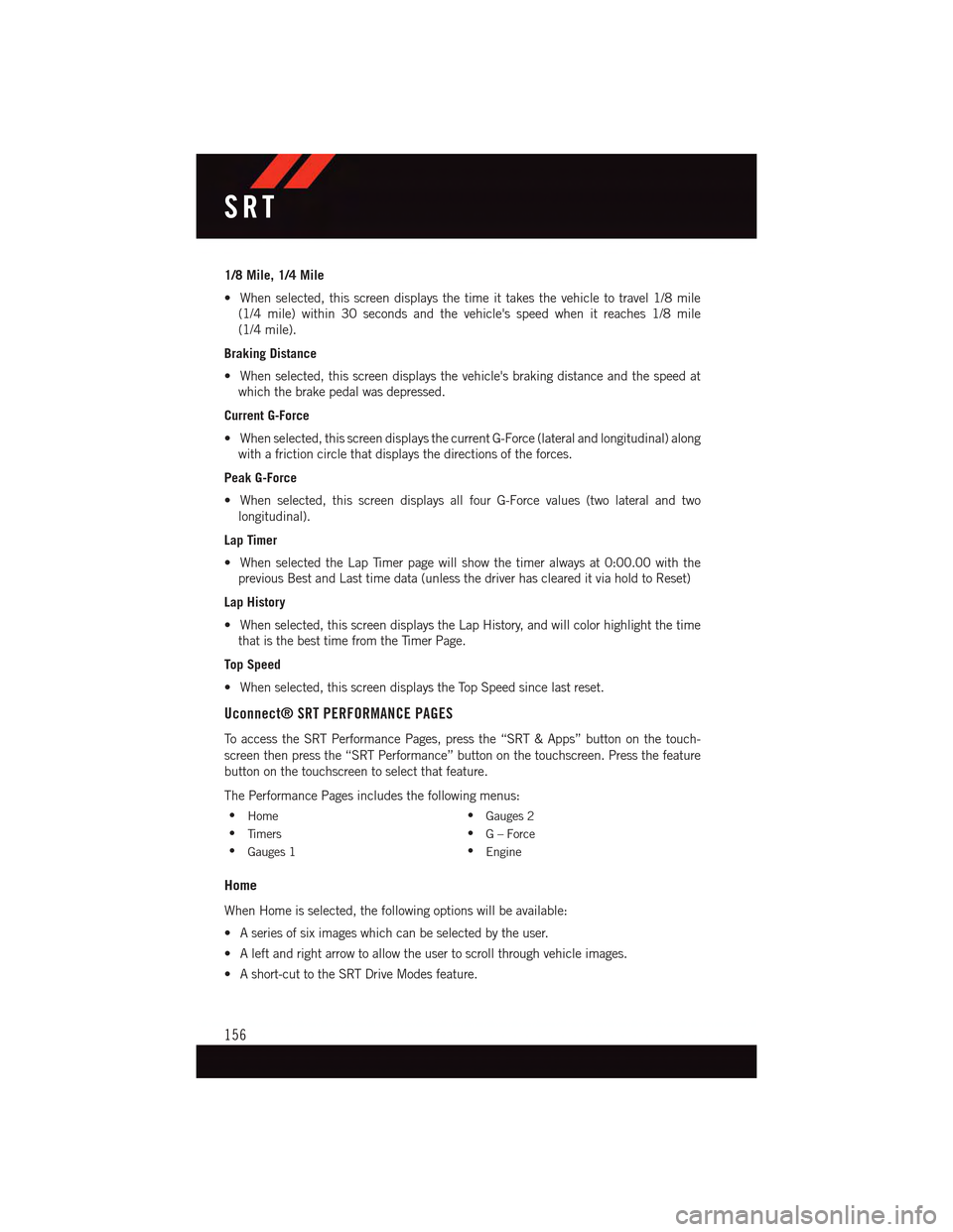
1/8 Mile, 1/4 Mile
•Whenselected,thisscreendisplaysthetimeittakesthevehicletotravel1/8mile
(1/4 mile) within 30 seconds and the vehicle's speed when it reaches 1/8 mile
(1/4 mile).
Braking Distance
•Whenselected,thisscreendisplaysthevehicle'sbrakingdistanceandthespeedat
which the brake pedal was depressed.
Current G-Force
•Whenselected,thisscreendisplaysthecurrentG-Force(lateralandlongitudinal)along
with a friction circle that displays the directions of the forces.
Peak G-Force
•Whenselected,thisscreendisplaysallfourG-Forcevalues(twolateralandtwo
longitudinal).
Lap Timer
•WhenselectedtheLapTimerpagewillshowthetimeralwaysat0:00.00withthe
previous Best and Last time data (unless the driver has cleared it via hold to Reset)
Lap History
•Whenselected,thisscreendisplaystheLapHistory,andwillcolorhighlightthetime
that is the best time from the Timer Page.
Top Speed
•Whenselected,thisscreendisplaystheTopSpeedsincelastreset.
Uconnect® SRT PERFORMANCE PAGES
To a c c e s s t h e S R T P e r f o r m a n c e P a g e s , p r e s s t h e “ S R T & A p p s ” b u t t o n o n t h e t o u c h -
screen then press the “SRT Performance” button on the touchscreen. Press the feature
button on the touchscreen to select that feature.
The Performance Pages includes the following menus:
•Home•Gauges 2
•Ti m e r s•G–Force
•Gauges 1•Engine
Home
When Home is selected, the following options will be available:
•Aseriesofsiximageswhichcanbeselectedbytheuser.
•Aleftandrightarrowtoallowtheusertoscrollthroughvehicleimages.
•Ashort-cuttotheSRTDriveModesfeature.
SRT
156
Page 165 of 236

WARNING!
Driving a vehicle with the red brake light on is dangerous. Part of the brake system may
have failed. It will take longer to stop the vehicle. You could have a collision. Have the
vehicle checked immediately.
Malfunction Indicator Light (MIL)
Certain conditions, such as a poor fuel quality, etc., may illuminate the MIL after engine
start. The vehicle should be serviced if the light stays on through several typical driving
cycles. In most situations, the vehicle will drive normally and not require towing.
If the MIL flashes when the engine is running, serious conditions may exist that could lead
to immediate loss of power or severe catalytic converter damage. We recommend you do
not operate the vehicle. Have the vehicle serviced immediately.
Electronic Stability Control (ESC) OFF Indicator Light
This light indicates the Electronic Stability Control (ESC) is off.
INSTRUMENT CLUSTER INDICATOR LIGHTS
Turn Signal Indicator
The arrows will flash with the exterior turn signals when the turn signal lever is operated.
Atonewillchime,andaDIDmessagewillappearifeitherturnsignalisleftonformore
than 1 mile (1.6 km).
NOTE:
If either indicator flashes at a rapid rate, check for a defective outside light bulb.
High Beam Indicator
Indicates that headlights are on high beam.
Front Fog Light Indicator
This indicator will illuminate when the front fog lights are on.
Vehicle Security Light
This light will flash rapidly for approximately 15 seconds when the vehicle security alarm
is arming. The light will flash at a slower speed continuously after the alarm is set. The
security light will also come on for about three seconds when the ignition is first turned on.
Electronic Speed Control Set
Indicates that the Electronic Speed Control has been set.
WHAT TO DO IN EMERGENCIES
163
Page 169 of 236

3. Remove the fastener securing the spare tire.
4. Remove the spare tire.
5. Remove the fastener securing the jack.
6.Remove the scissors jack and lug wrench
from the spare wheel as an assembly. Turn
the jack screw to the left to loosen the lug
wrench, and remove the wrench from the
jack assembly.
Spare Tire Fastener
Jack Fastener
WHAT TO DO IN EMERGENCIES
167
Page 182 of 236
WARNING!
•Whentemperaturesarebelowthefreezingpoint,electrolyteinadischargedbattery
may freeze. Do not attempt jump-starting because the battery could rupture or
explode and cause personal injury. Battery temperature must be brought above
freezing point before attempting a jump-start.
•Takecaretoavoidtheradiatorcoolingfanwheneverthehoodisraised.Itcanstart
anytime the ignition switch is on. You can be injured by moving fan blades.
•Removeanymetaljewelry,suchaswatchbandsorbracelets,thatmightmakean
inadvertent electrical contact. You could be severely injured.
•Batteriescontainsulfuricacidthatcanburnyourskinoreyesandgenerate
hydrogen gas which is flammable and explosive. Keep open flames or sparks away
from the battery.
•Donotallowvehiclestotoucheachotherasthiscouldestablishaground
connection and personal injury could result.
•Failuretofollowthisprocedurecouldresultinpersonalinjuryorpropertydamage
due to battery explosion.
•Donotconnectthecabletothenegativepost(-)of the discharged battery. The
resulting electrical spark could cause the battery to explode and could result in
personal injury.
MANUAL PARK RELEASE — 8 SPEED TRANSMISSION
WARNING!
Always secure your vehicle by fully applying the parking brake, before activating the
Manual Park Release. Activating the Manual Park Release will allow your vehicle to roll
away if it is not secured by the parking brake or by proper connection to a tow vehicle.
Activating the Manual Park Release on an unsecured vehicle could lead to serious
injury or death for those in or around the vehicle.
WHAT TO DO IN EMERGENCIES
180
Page 183 of 236
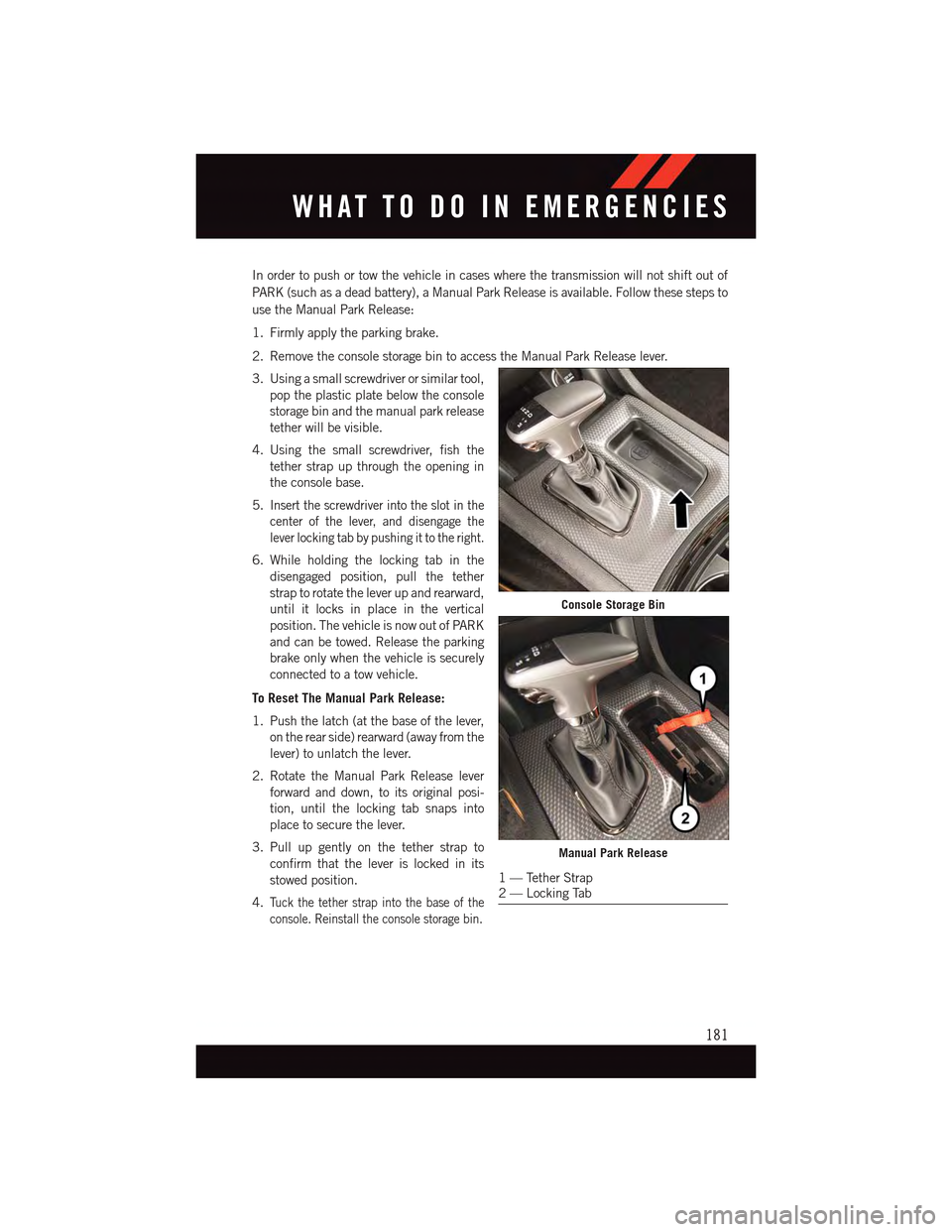
In order to push or tow the vehicle in cases where the transmission will not shift out of
PA R K ( s u c h a s a d e a d b a t t e r y ) , a M a n u a l P a r k R e l e a s e i s a v a i l a b l e . F o l l o w t h e s e s t e p s t o
use the Manual Park Release:
1. Firmly apply the parking brake.
2. Remove the console storage bin to access the Manual Park Release lever.
3. Using a small screwdriver or similar tool,
pop the plastic plate below the console
storage bin and the manual park release
tether will be visible.
4. Using the small screwdriver, fish the
tether strap up through the opening in
the console base.
5.Insert the screwdriver into the slot in the
center of the lever, and disengage the
lever locking tab by pushing it to the right.
6. While holding the locking tab in the
disengaged position, pull the tether
strap to rotate the lever up and rearward,
until it locks in place in the vertical
position. The vehicle is now out of PARK
and can be towed. Release the parking
brake only when the vehicle is securely
connected to a tow vehicle.
To Reset The Manual Park Release:
1. Push the latch (at the base of the lever,
on the rear side) rearward (away from the
lever) to unlatch the lever.
2. Rotate the Manual Park Release lever
forward and down, to its original posi-
tion, until the locking tab snaps into
place to secure the lever.
3. Pull up gently on the tether strap to
confirm that the lever is locked in its
stowed position.
4.Tu c k t h e t e t h e r s t r a p i n t o t h e b a s e o f t h e
console. Reinstall the console storage bin.
Console Storage Bin
Manual Park Release
1—TetherStrap2—LockingTab
WHAT TO DO IN EMERGENCIES
181
Page 210 of 236
FUSES
WARNING!
•When replacing a blown fuse, always use an appropriate replacement fuse with the
same amp rating as the original fuse. Never replace a fuse with another fuse of higher
amp rating. Never replace a blown fuse with metal wires or any other material. Failure
to use proper fuses may result in serious personal injury, fire and/or property damage.
•Beforereplacingafuse,makesurethattheignitionisoffandthatalltheother
services are switched off and/or disengaged.
•Ifthereplacedfuseblowsagain,contactanauthorizeddealer.
•If a general protection fuse for safety systems (air bag system, braking system), power
unit systems (engine system, gearbox system) or steering system blows, contact an
authorized dealer.
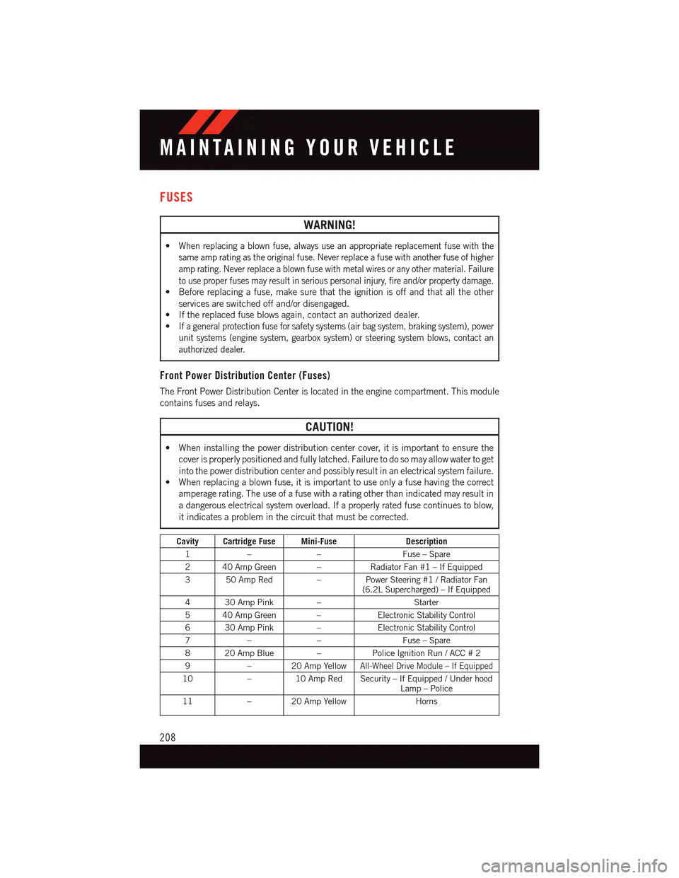
Front Power Distribution Center (Fuses)
The Front Power Distribution Center is located in the engine compartment. This module
contains fuses and relays.
CAUTION!
•Wheninstallingthepowerdistributioncentercover,itisimportanttoensurethe
cover is properly positioned and fully latched. Failure to do so may allow water to get
into the power distribution center and possibly result in an electrical system failure.•Whenreplacingablownfuse,itisimportanttouseonlyafusehavingthecorrect
amperage rating. The use of a fuse with a rating other than indicated may result in
adangerouselectricalsystemoverload.Ifaproperlyratedfusecontinuestoblow,
it indicates a problem in the circuit that must be corrected.
Cavity Cartridge Fuse Mini-FuseDescription
1––Fuse – Spare
240AmpGreen –Radiator Fan #1 – If Equipped
350AmpRed –Power Steering #1 / Radiator Fan(6.2L Supercharged) – If Equipped
430AmpPink –Starter
540AmpGreen –Electronic Stability Control
630AmpPink –Electronic Stability Control
7––Fuse – Spare
820AmpBlue –Police Ignition Run / ACC # 2
9–20AmpYellowAll-Wheel Drive Module – If Equipped
10–10AmpRedSecurity–IfEquipped/UnderhoodLamp – Police
11–20AmpYellowHorns
MAINTAINING YOUR VEHICLE
208