ESP DODGE CHARGER 2020 User Guide
[x] Cancel search | Manufacturer: DODGE, Model Year: 2020, Model line: CHARGER, Model: DODGE CHARGER 2020Pages: 412, PDF Size: 18.96 MB
Page 45 of 412
GETTING TO KNOW YOUR VEHICLE43
OUTSIDE MIRRORS
To receive maximum benefit, adjust the outside
mirror(s) to center on the adjacent lane of traffic
and a slight overlap of the view obtained from
the inside mirror.
NOTE:
The passenger side outside mirror will give a
much wider view to the rear, and especially of
the lane next to your vehicle.
DRIVER'S OUTSIDE AUTOMATIC
D
IMMING MIRROR — IF EQUIPPED
The driver’s outside mirror will automatically
adjust for glare from vehicles behind you. This
feature is controlled by the inside automatic
dimming mirror and will automatically adjust for
headlight glare when the inside mirror adjusts.
OUTSIDE MIRRORS APPROACH LIGHT —
I
F EQUIPPED
Driver and passenger outside mirrors equipped
with approach lighting contain one LED, which is
located in the upper outboard mirror glass
corner. The approach light supplies illuminated
entry lighting, which turns on in both mirrors
when you use the remote keyless entry key fob
or open any door. This LED shines outward to
illuminate the front and rear door handles. It
also shines downward to illuminate the area in
front of the doors.
POWER MIRRORS
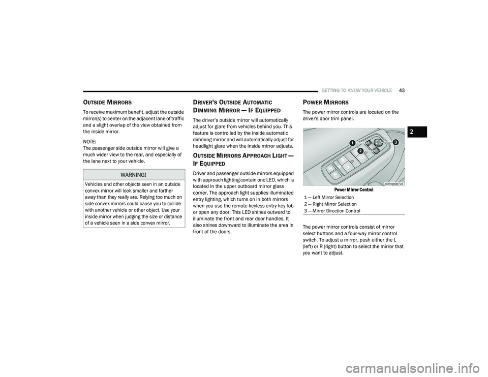
The power mirror controls are located on the
driver's door trim panel.
Power Mirror Control
The power mirror controls consist of mirror
select buttons and a four-way mirror control
switch. To adjust a mirror, push either the L
(left) or R (right) button to select the mirror that
you want to adjust.
WARNING!
Vehicles and other objects seen in an outside
convex mirror will look smaller and farther
away than they really are. Relying too much on
side convex mirrors could cause you to collide
with another vehicle or other object. Use your
inside mirror when judging the size or distance
of a vehicle seen in a side convex mirror.
1 — Left Mirror Selection
2 — Right Mirror Selection
3 — Mirror Direction Control
2
20_LD_OM_EN_USC_t.book Page 43
Page 54 of 412
52GETTING TO KNOW YOUR VEHICLE
RAIN SENSING WIPERS — IF EQUIPPED
This feature senses rain or snowfall on the
windshield and automatically activates the
wipers for the driver. The feature is especially
useful for road splash or overspray from the
windshield washers of the vehicle ahead.
Rotate the end of the multifunction lever to one
of four settings to activate this feature.
The sensitivity of the system can be adjusted
with the multifunction lever. Wiper delay
position 1 is the least sensitive, and wiper delay
position 4 is the most sensitive. Setting 3
should be used for normal rain conditions.
Settings 1 and 2 can be used if the driver
desires less wiper sensitivity. Setting 4 can be
used if the driver desires more sensitivity. Place
the wiper switch in the off position when not
using the system. NOTE:The Rain Sensing feature will not operate
when the wiper switch is in the low or
high-speed position.
The Rain Sensing feature may not function
properly when ice, or dried salt water is
present on the windshield.
Use of Rain-X or products containing wax or
silicone may reduce Rain Sensing perfor
-
mance.
The Rain Sensing system has protection
features for the wiper blades and arms, and will
not operate under the following conditions:
Low Ambient Temperature — When the igni-
tion is first placed in the ON position, the Rain
Sensing system will not operate until the
wiper switch is moved, vehicle speed is
greater than 0 mph (0 km/h), or the outside
temperature is greater than 32°F (0°C).
Transmission In NEUTRAL Position — When
the ignition is ON, and the transmission is in
the NEUTRAL position, the Rain Sensing
system will not operate until the wiper switch
is moved, vehicle speed is greater than
3 mph (5 km/h), or the gear selector is
moved out of the NEUTRAL position.
NOTE:
Rain Sensing can be turned on and off using the
Uconnect System, refer to “Uconnect Settings”
in “Multimedia” for further information.
CLIMATE CONTROLS
The Climate Control system allows you to
regulate the temperature, air flow, and direction
of air circulating throughout the vehicle. The
controls are located on the touchscreen (if
equipped) and on the instrument panel below
the radio.
20_LD_OM_EN_USC_t.book Page 52
Page 77 of 412
GETTING TO KNOW YOUR VEHICLE75
GENERAL INFORMATION
The following regulatory statement applies to all
Radio Frequency (RF) devices equipped in this
vehicle:
This device complies with Part 15 of the FCC
Rules and with Innovation, Science and
Economic Development Canada license-exempt
RSS standard(s). Operation is subject to the
following two conditions:
1. This device may not cause harmful
interference, and
2. This device must accept any interference received, including interference that may
cause undesired operation.
Le présent appareil est conforme aux CNR
d`Innovation, Science and Economic
Development applicables aux appareils radio
exempts de licence. L'exploitation est autorisée
aux deux conditions suivantes:
1. l'appareil ne doit pas produire de
brouillage, et
2. l'utilisateur de l'appareil doit accepter tout brouillage radioélectrique subi, même si le
brouillage est susceptible d'en compro -
mettre le fonctionnement.
La operación de este equipo está sujeta a las
siguientes dos condiciones:
1. es posible que este equipo o dispositivo no cause interferencia perjudicial y
2. este equipo o dispositivo debe aceptar cualquier interferencia, incluyendo la que
pueda causar su operación no deseada.
NOTE:
Changes or modifications not expressly
approved by the party responsible for compli -
ance could void the user’s authority to operate
the equipment.
WARNING!
Vehicle exhaust contains carbon monoxide,
a dangerous gas. Do not run your vehicle in
the garage while programming the trans -
ceiver. Exhaust gas can cause serious
injury or death.
Your motorized door or gate will open and
close while you are programming the
universal transceiver. Do not program the
transceiver if people, pets or other objects
are in the path of the door or gate. Only use
this transceiver with a garage door opener
that has a “stop and reverse” feature as
required by Federal safety standards. This
includes most garage door opener models
manufactured after 1982. Do not use a
garage door opener without these safety
features.
2
20_LD_OM_EN_USC_t.book Page 75
Page 90 of 412
88GETTING TO KNOW YOUR INSTRUMENT PANEL
Secondary Method Of Resetting Engine Oil Life
1. Without pressing the brake pedal, push the
ENGINE START/STOP button and place the
ignition to the ON/RUN position (do not
start the engine).
2. Fully press the accelerator pedal, slowly, three times within ten seconds.
3. Without pushing the brake pedal, push the ENGINE START/STOP button once to return
the ignition to the OFF/LOCK position.
NOTE:
If the indicator message illuminates when you
start the vehicle, the oil change indicator
system did not reset. If necessary, repeat this
procedure.
PERFORMANCE SHIFT INDICATOR (PSI)
— I
F EQUIPPED
The Performance Shift Indicator (PSI) is enabled
on vehicles with manual transmission, or when
a vehicle with automatic transmission is in
manual shift mode. The PSI provides the driver
with a visual indication within the instrument
cluster display when the driver configured gear
shift point has been reached and the driver is still accelerating. This indication notifies the
driver to change gear corresponding to the
configured RPMs in the head unit.
INSTRUMENT CLUSTER DISPLAY
S
ELECTABLE MENU ITEMS
Push and release the up or down arrow
button until the desired Selectable Menu item is
displayed in the instrument cluster display.
Follow the Menu or submenu prompts as
desired.
Speedometer
Push and release the up or down arrow
button until the speedometer menu is displayed
in the instrument cluster display. Push and
release the OK button to toggle units (km/h or
mph) of the speedometer.
Vehicle Info
Push and release the up or down arrow
button until the “Vehicle Info” menu is displayed
in the instrument cluster display. Push and
release the right or left arrow button to
scroll through the submenus items of “Vehicle
Info.” Follow the directional prompts to access or reset any of the following “Vehicle Info”
submenu items:
Tire Pressure
Coolant Temp
Trans Temp
Oil Temp
Oil Pressure
Oil Life
Battery Voltage
Storage Mode - Through this option, the
vehicle can be placed into Storage Mode.
AWD Status — If Equipped
Intake Air Temperature — If Equipped
Engine Torque — If Equipped
Engine Power — If Equipped
Air-Fuel Ratio — If Equipped
Boost Pressure — If Equipped
InterCooler (I/C) Temperature — If Equipped
20_LD_OM_EN_USC_t.book Page 88
Page 92 of 412
90GETTING TO KNOW YOUR INSTRUMENT PANEL
The following describes each feature and its
operation:
Driver Assist — If Equipped
The Driver Assist menu displays the status of
the ACC and LaneSense systems.
Push and release the up or down arrow
button until the Driver Assist menu is displayed
in the instrument cluster display.
Adaptive Cruise Control (ACC) Feature
The instrument cluster displays the current ACC
system settings. The information displayed
depends on ACC system status.
Push the Adaptive Cruise Control (ACC) on/off
button (located on the steering wheel) until one
of the following displays in the instrument
cluster display:
Adaptive Cruise Control Off
When ACC is deactivated, the display will read
“Adaptive Cruise Control Off.”
Adaptive Cruise Control Ready
When ACC is activated but the vehicle speed
setting has not been selected, the display will
read “Adaptive Cruise Control Ready.” Push the SET + or the SET- button (located on
the steering wheel) and the following will display
in the instrument cluster display:
ACC SET
When ACC is set, the set speed will display in
the instrument cluster.
The ACC screen may display once again if any
ACC activity occurs, which may include any of
the following:
Distance Setting Change
System Cancel
Driver Override
System Off
ACC Proximity Warning
ACC Unavailable Warning
For further information, refer to “Adaptive
Cruise Control (ACC) — If Equipped” in “Starting
And Operating.”
LaneSense — If Equipped
The instrument cluster displays the current
LaneSense system settings. The information
displayed depends on LaneSense system status and the conditions that need to be met.
For further information, refer to “LaneSense — If
Equipped” in “Starting And Operating.”
Fuel Economy
Two submenu pages; one with Current Value
(instantaneous calculation of the fuel economy)
displayed and one without the Current Value
displayed (toggle the
left or right arrow
button to select one):
Current Fuel Economy (MPG, L/100 km, or
km/L).
Range (miles or km).
Average Fuel Economy (MPG, L/100 km, or
km/L).
The Max and Min values will correspond to
the particular engine requirements.
Lower end of gauge will be displayed in an
amber color and turn green as Fuel Economy
improves.
Hold the OK button to reset average fuel
economy information.
20_LD_OM_EN_USC_t.book Page 90
Page 101 of 412
GETTING TO KNOW YOUR INSTRUMENT PANEL99
The “ESC OFF Indicator Light” and the “ESC
Indicator Light” come on momentarily each
time the ignition is placed in the ON/RUN or
ACC/ON/RUN position.
The ESC system will make buzzing or clicking
sounds when it is active. This is normal; the
sounds will stop when ESC becomes inactive.
This light will come on when the vehicle is in
an ESC event.
Electronic Stability Control (ESC) OFF
Warning Light — If Equipped
This warning light indicates the
Electronic Stability Control (ESC) is
off.
Each time the ignition is turned to ON/RUN or
ACC/ON/RUN, the ESC system will be on, even
if it was turned off previously.
The ESC OFF indicator will be lit any time the
Traction Mode is set to Sport, Track or Full OFF
in Drive Modes.
Low Washer Fluid Warning Light —
If Equipped
This warning light will illuminate when
the windshield washer fluid is low.
Refer to “Engine Compartment” in
“Servicing And Maintenance” for further
information.
Tire Pressure Monitoring System (TPMS)
Warning Light
The warning light switches on and a
message is displayed to indicate that
the tire pressure is lower than the
recommended value and/or that slow
pressure loss is occurring. In these cases,
optimal tire duration and fuel consumption may
not be guaranteed.
Should one or more tires be in the condition
mentioned above, the display will show the
indications corresponding to each tire. Each tire, including the spare (if provided),
should be checked monthly when cold and
inflated to the inflation pressure recommended
by the vehicle manufacturer on the vehicle
placard or tire inflation pressure label. If your
vehicle has tires of a different size than the size
indicated on the vehicle placard or tire inflation
pressure label, you should determine the
proper tire inflation pressure for those tires.
CAUTION!
Do not continue driving with one or more flat
tires as handling may be compromised. Stop
the vehicle, avoiding sharp braking and
steering. If a tire puncture occurs, repair
immediately using the dedicated tire repair
kit and contact an authorized dealer as soon
as possible.
3
20_LD_OM_EN_USC_t.book Page 99
Page 102 of 412
100GETTING TO KNOW YOUR INSTRUMENT PANEL
As an added safety feature, your vehicle has
been equipped with a Tire Pressure Monitoring
System (TPMS) that illuminates a low tire
pressure telltale when one or more of your tires is
significantly under-inflated. Accordingly, when
the low tire pressure telltale illuminates, you
should stop and check your tires as soon as
possible, and inflate them to the proper pressure.
Driving on a significantly under-inflated tire
causes the tire to overheat and can lead to tire
failure. Under-inflation also reduces fuel
efficiency and tire tread life, and may affect the
vehicle’s handling and stopping ability.
Please note that the TPMS is not a substitute for
proper tire maintenance, and it is the driver’s
responsibility to maintain correct tire pressure,
even if under-inflation has not reached the level
to trigger illumination of the TPMS low tire
pressure telltale. Your vehicle has also been equipped with a
TPMS malfunction indicator to indicate when
the system is not operating properly. The TPMS
malfunction indicator is combined with the low
tire pressure telltale. When the system detects
a malfunction, the telltale will flash for
approximately one minute and then remain
continuously illuminated. This sequence will
continue upon subsequent vehicle start-ups as
long as the malfunction exists. When the
malfunction indicator is illuminated, the system
may not be able to detect or signal low tire
pressure as intended. TPMS malfunctions may
occur for a variety of reasons, including the
installation of replacement or alternate tires or
wheels on the vehicle that prevent the TPMS
from functioning properly. Always check the
TPMS malfunction telltale after replacing one or
more tires or wheels on your vehicle to ensure
that the replacement or alternate tires and
wheels allow the TPMS to continue to function
properly.CAUTION!
The TPMS has been optimized for the original
equipment tires and wheels. TPMS pressures
and warning have been established for the
tire size equipped on your vehicle.
Undesirable system operation or sensor
damage may result when using replacement
equipment that is not of the same size, type,
and/or style. Aftermarket wheels can cause
sensor damage. Using aftermarket tire
sealants may cause the Tire Pressure
Monitoring System (TPMS) sensor to become
inoperable. After using an aftermarket tire
sealant it is recommended that you take your
vehicle to an authorized dealer to have your
sensor function checked.
20_LD_OM_EN_USC_t.book Page 100
Page 105 of 412
GETTING TO KNOW YOUR INSTRUMENT PANEL103
Turn Signal Indicator Lights
When the left or right turn signal is
activated, the turn signal indicator will
flash independently and the
corresponding exterior turn signal lamps
will flash. Turn signals can be activated when the
multifunction lever is moved down (left) or up (right).
NOTE:
A continuous chime will sound if the vehicle is
driven more than 1 mile (1.6 km) with either
turn signal on.
Check for an inoperative outside light bulb if
either indicator flashes at a rapid rate.
WHITE INDICATOR LIGHTS
Custom Mode Indicator Light
This light will turn on when Custom
Mode is active. Refer to the Drive
Modes Supplement for further
information.
Adaptive Cruise Control (ACC) Ready Light
— If Equipped
This light will turn on when Adaptive
Cruise Control (ACC) has been turned
on, but is not set. Refer to “Adaptive Cruise Control (ACC)” in “Starting And
Operating” for further information.
Cruise Control Ready Indicator
This indicator light will illuminate
when the cruise control is ready, but
not set. Refer to “Speed Control” in
“Starting And Operating” for further
information.
LaneSense Indicator Light — If Equipped
When the LaneSense system is on,
but not armed, the LaneSense
indicator light illuminates solid white.
This occurs when only left, right, or
neither lane line has been detected. If a single
lane line is detected, the system is ready to
provide only visual warnings if an unintentional
lane departure occurs on the detected lane line.
Refer to “LaneSense — If Equipped" in “Starting
And Operating” for further information.
Sport Mode Indicator Light — If Equipped
This light will turn on when Sport
Mode is active. Refer to the Drive
Modes Supplement for further
information.
Track Mode Indicator Light — If Equipped
This light will turn on when Track
Mode is active. Refer to the Drive
Modes Supplement for further
information.
Valet Mode SRT Indicator Light —
If Equipped
This light will turn on when Valet Mode
is active. Refer to the Drive Modes
Supplement for further information.
Speed Warning Indicator Light —
If Equipped
The indicator light will illuminate white
along with a notification text message
(Speed Warning Set to XX followed by
unit). When the set speed is just
exceeded, a single chime will sound along with
pop-up message of Speed Warning Exceeded.
When the set speed is exceeded by 2 mph
(3 km/h) or more, the indicator will light up yellow
and flash along with a continuous chime (up to 10
seconds or until the speed is no longer exceeded).
NOTE:
The number “55” is only an example of a speed
that can be selected.
3
20_LD_OM_EN_USC_t.book Page 103
Page 110 of 412
108SAFETY
Brake System Warning Light
The red “Brake System Warning Light” will turn
on when the ignition is placed in the ON/RUN
mode and may stay on for as long as four
seconds.
If the “Brake System Warning Light” remains on
or comes on while driving, it indicates that the
brake system is not functioning properly and
that immediate service is required. If the “Brake
System Warning Light” does not come on when
the ignition is placed in the ON/RUN mode,
have the light repaired as soon as possible.
Electronic Brake Force Distribution (EBD)
This function manages the distribution of the
braking torque between the front and rear axles
by limiting braking pressure to the rear axle.
This is done to prevent overslip of the rear
wheels to avoid vehicle instability, and to
prevent the rear axle from entering ABS before
the front axle.
Electronic Roll Mitigation (ERM)
Electronic Roll Mitigation (ERM) anticipates the
potential for wheel lift by monitoring the driver’s
steering wheel input and the speed of the
vehicle. When ERM determines that the rate of
change of the steering wheel angle and vehicle’s speed are sufficient to potentially cause wheel
lift, it then applies the appropriate brake and may
also reduce engine power to lessen the chance
that wheel lift will occur. ERM can only reduce the
chance of wheel lift occurring during severe or
evasive driving maneuvers; it cannot prevent
wheel lift due to other factors, such as road
conditions, leaving the roadway, or striking
objects or other vehicles.
NOTE:
ERM is disabled anytime the ESC is in “Full Off”
mode (if equipped). Refer to “Electronic Stability
Control (ESC)” in this section for a complete
explanation of the available ESC modes.
Electronic Stability Control (ESC)
The Electronic Stability Control (ESC) system
enhances directional control and stability of the
vehicle under various driving conditions. ESC
corrects for oversteering or understeering of the
vehicle by applying the brake of the appropriate
wheel(s) to assist in counteracting the oversteer
or understeer condition. Engine power may also
be reduced to help the vehicle maintain the
desired path.
ESC uses sensors in the vehicle to determine
the vehicle path intended by the driver and
compares it to the actual path of the vehicle.
When the actual path does not match the
intended path, ESC applies the brake of the
appropriate wheel to assist in counteracting the
oversteer or understeer condition.
Oversteer — when the vehicle is turning
more than appropriate for the steering
wheel position.
Understeer — when the vehicle is turning
less than appropriate for the steering wheel
position.
WARNING!
Many factors, such as vehicle loading, road
conditions and driving conditions, influence
the chance that wheel lift or rollover may
occur. ERM cannot prevent all wheel lift or roll
overs, especially those that involve leaving
the roadway or striking objects or other
vehicles. The capabilities of an
ERM-equipped vehicle must never be
exploited in a reckless or dangerous manner
which could jeopardize the user's safety or
the safety of others.
20_LD_OM_EN_USC_t.book Page 108
Page 114 of 412
112SAFETY
The gear selection must match vehicle uphill
direction (i.e., vehicle facing uphill is in
forward gear; vehicle backing uphill is in
REVERSE gear).
HSA will work in REVERSE gear and all
forward gears. The system will not activate if
the transmission is in PARK or NEUTRAL. For
vehicles equipped with a manual transmis -
sion, if the clutch is pressed, HSA will remain
active.
Towing With HSA
HSA will also provide assistance to mitigate roll
back while towing a trailer.
Disabling And Enabling HSA
This feature can be turned on or turned off. To
change the current setting, proceed as follows:
If disabling HSA using your instrument cluster
display, refer to “Instrument Cluster Display”
in “Getting To Know Your Instrument Panel”
for further information.
If disabling HSA using Uconnect Settings,
refer to “Uconnect Settings” in “Multimedia”
for further information.
For vehicles not equipped with an instrument
cluster display, perform the following steps:
1. Center the steering wheel (front wheels pointing straight forward).
2. Shift the transmission into PARK.
3. Apply the parking brake.
4. Start the engine.
5. Rotate the steering wheel slightly more than one-half turn to the left.
WARNING!
There may be situations where the Hill Start
Assist (HSA) will not activate and slight rolling
may occur, such as on minor hills or with a
loaded vehicle, or while pulling a trailer. HSA
is not a substitute for active driving
involvement. It is always the driver’s
responsibility to be attentive to distance to
other vehicles, people, and objects, and most
importantly brake operation to ensure safe
operation of the vehicle under all road
conditions. Your complete attention is always
required while driving to maintain safe control
of your vehicle. Failure to follow these
warnings can result in a collision or serious
personal injury.
WARNING!
If you use a trailer brake controller with your
trailer, the trailer brakes may be activated
and deactivated with the brake switch. If
so, there may not be enough brake pres -
sure to hold both the vehicle and the trailer
on a hill when the brake pedal is released.
In order to avoid rolling down an incline
while resuming acceleration, manually acti -
vate the trailer brake or apply more vehicle
brake pressure prior to releasing the brake
pedal.
HSA is not a parking brake. Always apply
the parking brake fully when exiting your
vehicle. Also, be certain to place the trans -
mission in PARK.
Failure to follow these warnings can result
in a collision or serious personal injury.
20_LD_OM_EN_USC_t.book Page 112