fuse DODGE CHARGER 2020 Owners Manual
[x] Cancel search | Manufacturer: DODGE, Model Year: 2020, Model line: CHARGER, Model: DODGE CHARGER 2020Pages: 412, PDF Size: 18.96 MB
Page 7 of 412
5
PARKSENSE REAR PARK ASSIST —
IF EQUIPPED ....................................................... 191 ParkSense Sensors ...................................192
ParkSense Warning Display ......................192
ParkSense Display ..................................... 192Enabling And Disabling ParkSense ..........194
Service The ParkSense Rear Park
Assist System .............................................195 Cleaning The ParkSense System ..............195
ParkSense System Usage Precautions ....195
LANESENSE — IF EQUIPPED ........................... 196
LaneSense Operation ................................196Turning LaneSense On Or Off ...................196LaneSense Warning Message ..................197
Changing LaneSense Status .....................199
PARKVIEW REAR BACK UP CAMERA ............. 199
REFUELING THE VEHICLE ................................. 200
VEHICLE LOADING ............................................ 202
Vehicle Certification Label ........................ 202Gross Vehicle Weight Rating (GVWR) .......202
Gross Axle Weight Rating (GAWR) ........... 202Overloading ................................................202
Loading ......................................................203
TRAILER TOWING .............................................. 203
Common Towing Definitions .....................203Trailer Hitch Classification ........................ 205Trailer Towing Weights (Maximum Trailer
Weight Ratings) ..........................................205 Trailer And Tongue Weight ....................... 206
Towing Requirements................................ 206
Towing Tips ................................................ 209
RECREATIONAL TOWING (BEHIND MOTORHOME,
ETC.) ....................................................................210
DRIVING TIPS ...................................................... 210
Driving On Slippery Surfaces .................... 210
Driving Through Water .............................. 211
IN CASE OF EMERGENCY
HAZARD WARNING FLASHERS .......................212
ASSIST AND SOS MIRROR — IF EQUIPPED .... 212General Information .................................. 216
BULB REPLACEMENT ........................................ 217
Replacement Bulbs ................................... 217
Replacing Exterior Bulbs ........................... 219
FUSES ..................................................................220
General Information .................................. 220Underhood Fuses ...................................... 221
Rear Interior Fuses .................................... 225
JACKING AND TIRE CHANGING ........................229
Jack Location/Spare Tire Stowage ........... 230
Preparations For Jacking........................... 230
Jacking And Changing A Tire ..................... 231Road Tire Installation ................................ 234 TIRE SERVICE KIT — IF EQUIPPED ................... 234
Tire Service Kit Storage............................. 234
Tire Service Kit Components And
Operation ................................................... 235 Tire Service Kit Usage Precautions .......... 235Sealing A Tire With Tire Service Kit .......... 237
JUMP STARTING ............................................... 240
Preparations For Jump Start ..................... 240
Jump Starting Procedure .......................... 241
IF YOUR ENGINE OVERHEATS ......................... 242
MANUAL PARK RELEASE — 8 – SPEED
TRANSMISSION ................................................. 243
FREEING A STUCK VEHICLE ............................. 244
SRT — TOWING A DISABLED VEHICLE ............ 246
NON SRT — TOWING A DISABLED VEHICLE ... 248 All Wheel Drive (AWD) Models .................. 249Rear-Wheel Drive (RWD) Models ............. 249
ENHANCED ACCIDENT RESPONSE SYSTEM
(EARS) ................................................................ 249
EVENT DATA RECORDER (EDR) ....................... 249
SERVICING AND MAINTENANCE
SCHEDULED SERVICING .................................. 250
3.6L And 5.7L Engines ............................. 250
6.2L Supercharged And 6.4L Engines ..... 254
20_LD_OM_EN_USC_t.book Page 5
Page 80 of 412
78GETTING TO KNOW YOUR VEHICLE
ELECTRICAL POWER OUTLETS
Your vehicle is equipped with one 12 Volt
(13 Amp) power outlet on the instrument panel
and one 12 Volt (13 Amp) power outlet in the
center console that can be used to power
cellular phones, small electronics and other low
powered electrical accessories. The power
outlets are labeled with either a “key” or a
“battery” symbol to indicate how the outlet is
powered. Power outlets labeled with a “key” are
powered when the ignition switch is in the ACC
or ON/RUN position, while the outlets labeled
with a “battery” are connected directly to the
battery and powered at all times.
NOTE:
All accessories connected to the “battery”
powered outlets should be removed or turned
off when the vehicle is not in use to protect the
battery against discharge.
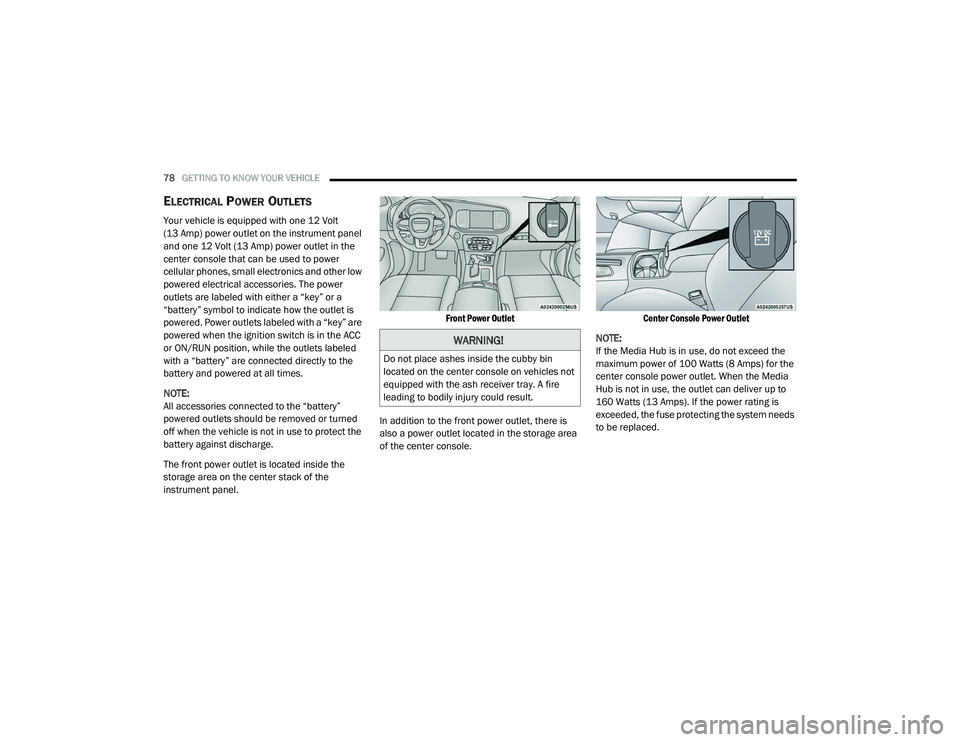
The front power outlet is located inside the
storage area on the center stack of the
instrument panel.
Front Power Outlet
In addition to the front power outlet, there is
also a power outlet located in the storage area
of the center console.
Center Console Power Outlet
NOTE:
If the Media Hub is in use, do not exceed the
maximum power of 100 Watts (8 Amps) for the
center console power outlet. When the Media
Hub is not in use, the outlet can deliver up to
160 Watts (13 Amps). If the power rating is
exceeded, the fuse protecting the system needs
to be replaced.
WARNING!
Do not place ashes inside the cubby bin
located on the center console on vehicles not
equipped with the ash receiver tray. A fire
leading to bodily injury could result.
20_LD_OM_EN_USC_t.book Page 78
Page 81 of 412
GETTING TO KNOW YOUR VEHICLE79
(Continued)
(Continued)
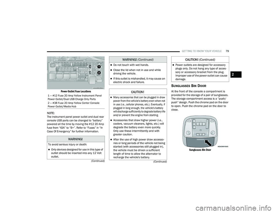
Power Outlet Fuse Locations
NOTE:
The instrument panel power outlet and dual rear
console USB ports can be changed to “battery”
powered all the time by moving the #12 20 Amp
fuse from “IGN” to “B+”. Refer to “Fuses” in “In
Case Of Emergency” for further information.
SUNGLASSES BIN DOOR
At the front of the console a compartment is
provided for the storage of a pair of sunglasses.
The storage compartment access is a “push/
push” design. Push the chrome pad on the door
to open. Push the chrome pad on the door to
close.
Sunglasses Bin Door
1 — #12 Fuse 20 Amp Yellow Instrument Panel
Power Outlet/Dual USB Charge Only Ports
2 — #38 Fuse 20 Amp Yellow Center Console
Power Outlet/Media Hub
WARNING!
To avoid serious injury or death:
Only devices designed for use in this type of
outlet should be inserted into any 12 Volt
outlet.
Do not touch with wet hands.
Close the lid when not in use and while
driving the vehicle.
If this outlet is mishandled, it may cause an
electric shock and failure.
CAUTION!
Many accessories that can be plugged in draw
power from the vehicle's battery even when not
in use (i.e., cellular phones, etc.). Eventually, if
plugged in long enough, the vehicle's battery
will discharge sufficiently to degrade battery life
and/or prevent the engine from starting.
Accessories that draw higher power (i.e.,
coolers, vacuum cleaners, lights, etc.) will
degrade the battery even more quickly.
Only use these intermittently and with
greater caution.
After the use of high power draw accesso -
ries or long periods of the vehicle not being
started (with accessories still plugged in),
the vehicle must be driven a sufficient
length of time to allow the alternator to
recharge the vehicle's battery.
WARNING! (Continued)
Power outlets are designed for accessory
plugs only. Do not hang any type of acces -
sory or accessory bracket from the plug.
Improper use of the power outlet can cause
damage.
CAUTION! (Continued)
2
20_LD_OM_EN_USC_t.book Page 79
Page 222 of 412
220IN CASE OF EMERGENCY
(Continued)
Front/Rear Side Marker Lamp
The Side Markers use LED lamps that are not
serviceable separately. The Side Markers must
be replaced as an assembly, see an authorized
dealer.
Front Fog Lamp
The Front Fog Lamps use LED sources that are
not serviceable separately. The Front Fog Lamp
must be replaced as an assembly; see an
authorized dealer.
Front Turn Signal Lamps
The Front Park/Turn function is part of the
headlamp assembly and use LED lamps that
are not serviceable separately. The headlamps
must be replaced as an assembly, see an
authorized dealer.
Backup Lamps
The Backup Lamps use LED sources that are
not serviceable separately. The Applique must
be replaced as an assembly; see an authorized
dealer.
License Lamp
The License Lamp uses an LED source that is
not serviceable separately. The License Lamp
must be replaced as an assembly; see an
authorized dealer.
Center High Mounted Stop Lamp (CHMSL)
The CHMSL Lamp uses LED sources that are
not serviceable separately. The CHMSL Lamp
must be replaced as an assembly; see an
authorized dealer.
FUSES
GENERAL INFORMATION
The fuses protect electrical systems against
excessive current.
When a device does not work, you must check
the fuse element inside the blade fuse for a
break/melt.
WARNING!
When replacing a blown fuse, always use
an appropriate replacement fuse with the
same amp rating as the original fuse. Never
replace a fuse with another fuse of higher
amp rating. Never replace a blown fuse with
metal wires or any other material. Do not
place a fuse inside a circuit breaker cavity
or vice versa. Failure to use proper fuses
may result in serious personal injury, fire
and/or property damage.
Before replacing a fuse, make sure that the
ignition is off and that all the other services
are switched off and/or disengaged.
If the replaced fuse blows again, contact an
authorized dealer.
If a general protection fuse for safety
systems (air bag system, braking system),
power unit systems (engine system, trans-
mission system) or steering system blows,
contact an authorized dealer.
WARNING! (Continued)
20_LD_OM_EN_USC_t.book Page 220
Page 223 of 412
IN CASE OF EMERGENCY221
Also, please be aware that when using power
outlets for extended periods of time with the
engine off may result in vehicle battery
discharge.
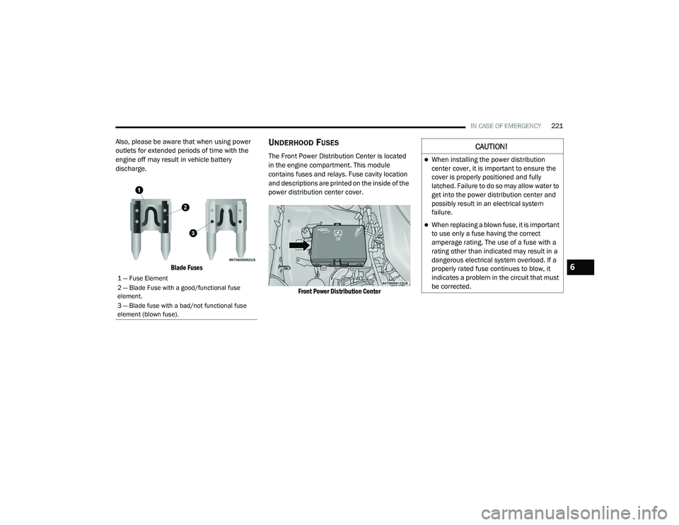
Blade Fuses
UNDERHOOD FUSES
The Front Power Distribution Center is located
in the engine compartment. This module
contains fuses and relays. Fuse cavity location
and descriptions are printed on the inside of the
power distribution center cover.
Front Power Distribution Center
1 — Fuse Element
2 — Blade Fuse with a good/functional fuse
element.
3 — Blade fuse with a bad/not functional fuse
element (blown fuse).
CAUTION!
When installing the power distribution
center cover, it is important to ensure the
cover is properly positioned and fully
latched. Failure to do so may allow water to
get into the power distribution center and
possibly result in an electrical system
failure.
When replacing a blown fuse, it is important
to use only a fuse having the correct
amperage rating. The use of a fuse with a
rating other than indicated may result in a
dangerous electrical system overload. If a
properly rated fuse continues to blow, it
indicates a problem in the circuit that must
be corrected.
6
20_LD_OM_EN_USC_t.book Page 221
Page 224 of 412
222IN CASE OF EMERGENCY
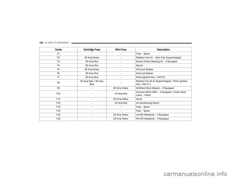
CavityCartridge Fuse Mini-Fuse Description
F1––Fuse – Spare
F2 40 Amp Green –Radiator Fan #1 – (Non 6.2L Supercharged)
F3 50 Amp Red –Electric Power Steering #1 – If Equipped
F4 30 Amp Pink –Starter
F5 40 Amp Green –Anti-Lock Brakes
F6 30 Amp Pink –Anti-Lock Brakes
F7 20 Amp Blue –Police Ignition Run / ACC #1
F8 50 Amp Red / 20 Amp
Blue –Radiator Fan (6.2L Supercharged) / Police Ignition
Run / ACC # 2
F9 –20 Amp Yellow All-Wheel Drive Module – If Equipped
F10 –10 Amp RedIntrusion MOD (300) – If Equipped / Under Hood
Lamp – Police
F11 –20 Amp Yellow Horns
F12 –10 Amp Red Air Conditioning Clutch
F13 ––Fuse – Spare
F14 ––Fuse – Spare
F15 –20 Amp Yellow LH HID Headlamp – If Equipped
F16 –20 Amp Yellow RH HID Headlamp – If Equipped
20_LD_OM_EN_USC_t.book Page 222
Page 225 of 412
IN CASE OF EMERGENCY223
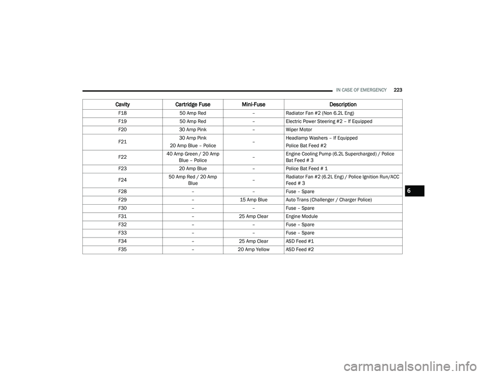
F18 50 Amp Red –Radiator Fan #2 (Non 6.2L Eng)
F19 50 Amp Red –Electric Power Steering #2 – If Equipped
F20 30 Amp Pink –Wiper Motor
F21 30 Amp Pink
20 Amp Blue – Police –Headlamp Washers – If Equipped
Police Bat Feed #2
F22 40 Amp Green / 20 Amp
Blue – Police –Engine Cooling Pump (6.2L Supercharged) / Police
Bat Feed # 3
F23 20 Amp Blue –Police Bat Feed # 1
F24 50 Amp Red / 20 Amp
Blue –Radiator Fan #2 (6.2L Eng) / Police Ignition Run/ACC
Feed # 3
F28 ––Fuse – Spare
F29 –15 Amp Blue Auto Trans (Challenger / Charger Police)
F30 ––Fuse – Spare
F31 –25 Amp Clear Engine Module
F32 ––Fuse – Spare
F33 ––Fuse – Spare
F34 –25 Amp Clear ASD Feed #1
F35 –20 Amp Yellow ASD Feed #2
Cavity Cartridge Fuse Mini-Fuse Description
6
20_LD_OM_EN_USC_t.book Page 223
Page 226 of 412
224IN CASE OF EMERGENCY
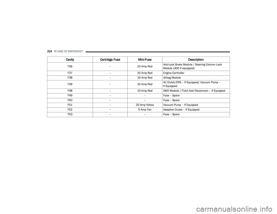
F36 –10 Amp RedAnti-Lock Brake Module / Steering Column Lock
Module (300 if equipped)
F37 –10 Amp Red Engine Controller
F38 –10 Amp Red Airbag Module
F39 –10 Amp RedAC Clutch/EPS – If Equipped/ Vacuum Pump –
If Equipped
F48 –10 Amp Red AWD Module / Front Axle Disconnect – If Equipped
F49 ––Fuse – Spare
F50 ––Fuse – Spare
F51 –20 Amp Yellow Vacuum Pump – If Equipped
F52 –5 Amp Tan Adaptive Cruise – If Equipped
F53 ––Fuse – Spare
Cavity Cartridge Fuse Mini-Fuse Description
20_LD_OM_EN_USC_t.book Page 224
Page 227 of 412
IN CASE OF EMERGENCY225
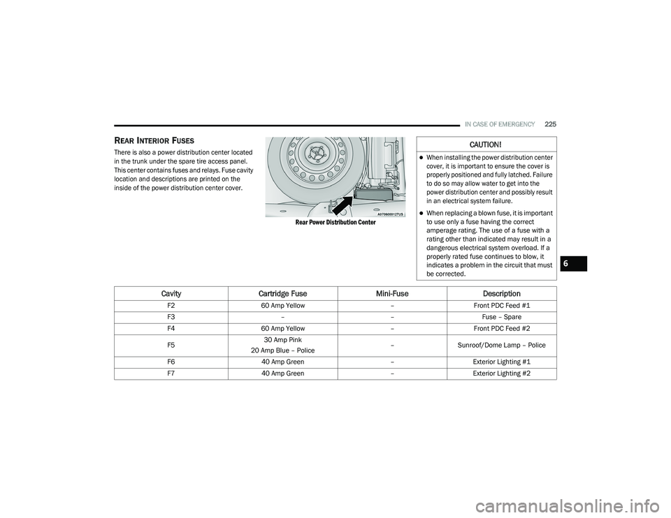
REAR INTERIOR FUSES
There is also a power distribution center located
in the trunk under the spare tire access panel.
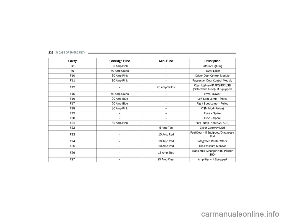
This center contains fuses and relays. Fuse cavity
location and descriptions are printed on the
inside of the power distribution center cover.
Rear Power Distribution Center
CAUTION!
When installing the power distribution center
cover, it is important to ensure the cover is
properly positioned and fully latched. Failure
to do so may allow water to get into the
power distribution center and possibly result
in an electrical system failure.
When replacing a blown fuse, it is important
to use only a fuse having the correct
amperage rating. The use of a fuse with a
rating other than indicated may result in a
dangerous electrical system overload. If a
properly rated fuse continues to blow, it
indicates a problem in the circuit that must
be corrected.
CavityCartridge Fuse Mini-FuseDescription
F260 Amp Yellow –Front PDC Feed #1
F3 ––Fuse – Spare
F4 60 Amp Yellow –Front PDC Feed #2
F5 30 Amp Pink
20 Amp Blue – Police –
Sunroof/Dome Lamp – Police
F6 40 Amp Green –Exterior Lighting #1
F7 40 Amp Green –Exterior Lighting #2
6
20_LD_OM_EN_USC_t.book Page 225
Page 228 of 412
226IN CASE OF EMERGENCY
F8 30 Amp Pink –Interior Lighting
F9 40 Amp Green –Power Locks
F10 30 Amp Pink –Driver Door Control Module
F11 30 Amp Pink –Passenger Door Control Module
F12 –20 Amp YellowCigar Lighter/IP APO/RR USB
(Selectable Fuse)– If Equipped
F15 40 Amp Green –HVAC Blower
F16 20 Amp Blue –Left Spot Lamp – Police
F17 20 Amp Blue –Right Spot Lamp – Police
F18 30 Amp Pink –VISM Mod (Police)
F19 ––Fuse – Spare
F20 ––Fuse – Spare
F21 30 Amp Pink –Fuel Pump (Non 6.2L ADR)
F22 –5 Amp Tan Cyber Gateway Mod
F23 –10 Amp RedFuel Door – If Equipped/Diagnostic
Port
F24 –10 Amp RedIntegrated Center Stack
F25 –10 Amp Red Tire Pressure Monitor
F26 –15 Amp BlueTrans Mod (Charger Non- Police/
300)
F27 –25 Amp Clear Amplifier – If Equipped
CavityCartridge Fuse Mini-FuseDescription
20_LD_OM_EN_USC_t.book Page 226